Table of Contents
Advertisement
Quick Links
Advertisement
Table of Contents

Related Manuals for MICRO-EPSILON optoNCDT ILR2250


Summary of Contents for MICRO-EPSILON optoNCDT ILR2250
- Page 1 Operating Instructions optoNCDT ILR2250 ILR2250-100 MICRO-EPSILON Eltrotec GmbH Manfred-Wörner-Straße 101 · 73037 Göppingen / Germany Tel. +49 (0) 7161/98872-300 · Fax +49 (0) 7161/98872-303 info@micro-epsilon.de · www.micro-epsilon.de Your local contact: www.micro-epsilon.com/contact/worldwide/...
- Page 2 Laser distance measuring device Non-contact laser-optic distance sensor MICRO-EPSILON Eltrotec GmbH Manfred-Wörner-Straße 101 73037 Göppingen / Germany Tel. +49 (0) 7161 / 98872-300 Fax +49 (0) 7161 / 98872-303 e-mail info@micro-epsilon.de www.micro-epsilon.com...
-
Page 3: Table Of Contents
Preliminary Remarks ............................29 Measurement Data Format ..........................29 Resetting the Baud Rate ..........................30 Cleaning ..........................31 Software Support with MEDAQLib ..................31 Liability for Material Defects ....................32 Service, Repair ........................32 Decommissioning, Disposal ....................32 optoNCDT ILR2250... - Page 4 SETDEFAULT, Factory Settings ....................40 A 3.6.4 LASER ............................40 A 3.6.5 ROI, Region of Interest ......................... 40 A 3.7 Data Output..............................40 A 3.7.1 OUTPUT ............................40 A 3.7.2 GETOUTINFO_RS422, Data Selection Query ................40 A 3.7.3 ANALOGSCALERANGE ....................... 40 optoNCDT ILR2250...
-
Page 5: Safety
Do not touch the lenses or protective windows. Remove any fingerprints immediately using pure alcohol and a clean cotton cloth without leaving any streaks. > Damage to or destruction of the sensor > Failure of the measuring device optoNCDT ILR2250 Page 5... -
Page 6: Notes On Ce Marking
The EU Declaration of Conformity is available to the responsible authorities according to EU Directive, Article 10. Intended Use - The optoNCDT ILR2250 is designed for use in industrial and laboratory applications. It is used for ƒ Distance, displacement and position measurement ƒ... -
Page 7: Laser Safety
Laser Safety The optoNCDT ILR2250 works with a semi-conductor laser at a wavelength of 655 nm (visible/red). The sensors fall within laser class 2. The laser is pulsed; the maximum optical power is ≤ 1 mW. The pulse frequency de- pends on the measuring rate set (1 ... -
Page 8: Functional Principle, Technical Data
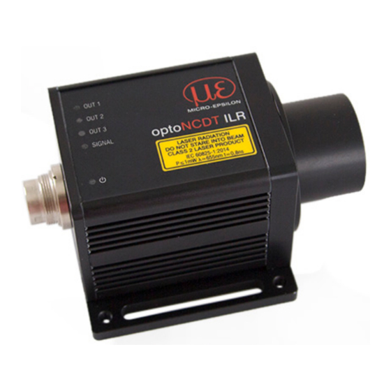
Short Description The optoNCDT ILR2250 is a laser distance measuring device that precisely measures distances in the range of 0.05 m to 150 m without contact. The measurement target can be clearly identified by the red laser measuring point. The maximum range depends on the reflectivity and surface properties of the target. -
Page 9: Technical Data
2) ILR-RF210 reflector film 210 x 297 mm; art. 7966058 3) Measured in the range of 0.05 … 20 m; statistical spread 2s 4) Measurement frequency of 20 Hz, moving average 10 5) Connection via interface module (IF2001/USB or IF2004/USB) optoNCDT ILR2250 Page 9... -
Page 10: Delivery
If there is damage or parts are missing, immediately contact the manufacturer or supplier. Optional accessories are listed in the appendix, see Chap. A 1. Storage Temperature range for storage: -25 ... +70 °C Humidity: 5 ... 95% (non-condensing) optoNCDT ILR2250 Page 10... -
Page 11: Installation And Assembly
Reflectance of Target Surface The optoNCDT ILR2250-100 sensor is an optical system used to measure in the millimeter range. The sensor works based on the phase comparison method and evaluates the direct and diffuse reflections of the laser beam sent back. -
Page 12: Interferences
5.1.2.1 Ambient Light The optoNCDT ILR2250 sensors are very good at suppressing ambient light thanks to their in-built optical interference filter. Nevertheless, highly reflective targets can cause errors on account of the glare caused by the strong reflections. If this happens, a less reflective surface should be used. The ideal target is white, slightly shiny and with a smooth surface. -
Page 13: Mechanical Fastening
4 x M4 2 x 4.8 x 45 Fig. 7 Dimensional drawing optoNCDT ILR2250-100, dimensions in mm (inches) Position the sensor so that the connections and display elements are not concealed. We recommend maintaining a clearance of 2–3 centimeters at the cooling ribs on the left and right sides. -
Page 14: Start Of Measuring Range
Warm-up phase The Signal LED indicates the reflection strength of a measurement. This LED generally lights up when a measurement is started. 1) Reduced measurement accuracy and measuring frequency possible 2) For sensors with optional heating optoNCDT ILR2250 Page 14... -
Page 15: Electrical Connections
The various peripheral devices can be connected to the sensor. The IF2001/USB, IF2004/USB and IF2008/ETH converters also supply the operating voltage (24 V DC) to the sensor. The voltage supply for the converters is provided, for example, by the optionally available PS 2020 power supply. optoNCDT ILR2250 Page 15... -
Page 16: Pin Assignment
10 ... of impulse interference at the same time. 30 VDC ILR2250 MICRO-EPSILON recommends using the optionally available PS2020 power supply, see Chap. A 1, for the sensor. red/blue Supply ground Fig. -
Page 17: Analog Output
The current impressed in the line is proportional to the measured distance. You can find more details on this in the Ana- log Output section, see Chap. 6.6. The measured values are always output via the analog output. optoNCDT ILR2250 Page 17... -
Page 18: Rs422 (With If2001/Usb Converter)
Cable color Function Function from the voltage (Cable: PC1100-x) supply. White Use a shielded cable Brown with twisted wires, Gray e.g. PC1100-x. Pink Purple Fig. 13 Crossed data lines on receive and transmit side optoNCDT ILR2250 Page 18... -
Page 19: Trigger Input
PNP (High side) Approx. GND Push-pull Push-pull, negated Fig. 16 Switching output behavior The switching output is activated when there is no target, when the target is too close/far or when no valid measurement value can be determined. optoNCDT ILR2250 Page 19... -
Page 20: Operation
Launch the sensorTOOL program and click on the button. The program will now search for connected ILR2250 sensors on the available interfaces. Select a desired sensor. Click the Start Data Acquisition button. Fig. 17 Auxiliary sensor search program optoNCDT ILR2250 Page 20... - Page 21 Operation Fig. 18 Measurement view in the sensorTOOL program You can access the functions (e.g. triggering, switching outputs and analog output) via the Settings tab. Fig. 19 Settings tab in the sensorTOOL program optoNCDT ILR2250 Page 21...
-
Page 22: Data Acquisition, Presets
The value ranges for the parameters - upper and lower limit (digital outputs), - analog output scaling, must be within the region of interest. Fields with gray background Fields with dark border Value require a selection. require entry of a value. optoNCDT ILR2250 Page 22... -
Page 23: Triggering
W = Displacement signal Fig. 23 High trigger level (top) with analog output A and RS422 output signal D (bottom) Fields with gray background Fields with dark border Value require a selection. require entry of a value. optoNCDT ILR2250 Page 23... -
Page 24: Triggering Measured Value Acquisition
Acquisition triggering therefore has a direct impact on the further processing of measured values. The sensor corrects errors internally based on the settings in the saved configurations. In the case of moving targets and data acquisition triggering, Micro-Epsilon recommends the Auto and Fast modes. 6.5.3 Triggering Measured Value Output The measured values are computed continuously and independently of the trigger event. -
Page 25: Analog Output
Teach range in mm [0; MR] the target and on whether a Distance in mm [m; n] reflector film is used. Fields with gray background Fields with dark border Value require a selection. require entry of a value. optoNCDT ILR2250 Page 25... -
Page 26: Switching Outputs, Limit Value Monitoring
Switch to the Settings > Digital outputs menu and select the desired conditions. Fig. 26 Digital outputs menu, for monitoring limit values, etc. Fields with gray background Fields with dark border Value require a selection. require entry of a value. optoNCDT ILR2250 Page 26... -
Page 27: Measured Value Holding Mode, Error Handling
After the selected number of cycles have elapsed, an error value is output. Fields with gray background Fields with dark border Value require a selection. require entry of a value. optoNCDT ILR2250 Page 27... -
Page 28: System Settings
Fig. 28 Settings menu with the Save button 6.9.2 Language The following languages are available in the sensorTOOL: - German - English - Chinese - Korean - Japanese. Switch the language in the menu bar. Fig. 29 Language selection in the menu bar optoNCDT ILR2250 Page 28... -
Page 29: Rs422 Digital Interface
Then, they are reformatted into big-endian format. The result can then be assigned to an unsigned integer with 32 bits. The first 4 bits are 0, as the ILR2250 transmits the distance with 28 bits. Fig. 31 Distance bytes in the correct order (big endian) optoNCDT ILR2250 Page 29... -
Page 30: Resetting The Baud Rate
The sensor can continue to supply measured values to the RS422 output even while the sensor is communicating. The IF2001 converter from MICRO-EPSILON, which is connected to the sensor via the PC1100-x standard cable (also optional), is suitable for data exchange with a PC, see Chap. -
Page 31: Cleaning
- works regardless of the type of interface used, - uses the same functions for communication (commands), - provides a single transmission format for all MICRO-EPSILON sensors. For C/C++ programmers, an additional header file and a library file are integrated into MEDAQLib. -
Page 32: Liability For Material Defects
The liability for material defects is 12 months from delivery. During this period any defective parts, with the exception of parts subject to wear, will be repaired or replaced at no cost when sent to MICRO-EPSILON. Any damage that is caused by improper handling, the use of force or by repairs or modifications by third parties is not covered by the liability for material defects. -
Page 33: Appendix
Switching output 1/2/3 Inactive Output level: push-pull Range check: both Lower limit: 0.0 mm Upper limit: 150000.0 mm Hysteresis: 0.0 mm Signal level hold: 1 ms 1) All lengths are also available in a drag chain-compatible design. optoNCDT ILR2250 Page 33... -
Page 34: A 3 Ascii Communication With Sensor
(“Wxxx”) may be output. Warnings are structured analogously to error messages. In the case of warning messages, the command has been executed. For support requests regarding the sensor, the responses to the commands GETINFO and PRINT are helpful because they contain the sensor settings. optoNCDT ILR2250 Page 34... -
Page 35: Commands Overview
Chap. A 3.6.4 Chap. A 3.6.5 Region of interest masking Data Output Chap. A 3.7.1 OUTPUT Measured value output selection Chap. A 3.7.2 GETOUTINFO_RS422 List intended data for RS422 ANALOGSCALERANGE Analog output scaling limits Chap. A 3.7.3 optoNCDT ILR2250 Page 35... -
Page 36: A 3.3 General Commands
//Sensor option number Article: 7112015 //Sensor article number Measuring range: 150000.0mm //Measuring range of sensor Version: //Software version Hardware-rev: -> A 3.3.3 GETTEMP GETTEMP Reports the inner temperature of the sensor in °C with one decimal place. optoNCDT ILR2250 Page 36... -
Page 37: A 3.3.4 Reset, Rebooting Sensor
- PULSE: Level triggering - SOFTWARE: Software triggering A 3.4.2 TRIGGERAT TRIGGERAT [INPUT|OUTPUT] Defines the type of triggering for data acquisition or data output. - INPUT: Triggers measured value acquisition. - OUTPUT: Triggers measured value output. optoNCDT ILR2250 Page 37... -
Page 38: Triggerlevel
- UPPER: The measured value is monitored to check whether it is greater than the limit value. - BOTH: The measured value is monitored to check whether it is less than or greater than the limit value. optoNCDT ILR2250 Page 38... -
Page 39: Errorlimitvalues1/2/3
- <mode>: Name of a configuration listed with the subcommand PRESETMODE. A 3.6.2 BASICSETTINGS BASICSETTINGS [READ|STORE] - READ: Loads the saved device settings from the sensor. - STORE: Saves the current device settings in the sensor. optoNCDT ILR2250 Page 39... -
Page 40: A 3.6.3 Setdefault, Factory Settings
Value range: <limit 1> = (-2 to +2) * measuring range [mm] <limit 2> = (-2 to +2) * measuring range [mm] The scaling limits must not be identical; <lower> is less than <upper>. <lower> Value range between SMR and EMR (mm, one decimal place) <upper> Value range between SMR and EMR (mm, one decimal place) optoNCDT ILR2250 Page 40... - Page 41 Appendix | ASCII Communication with Sensor optoNCDT ILR2250 Page 41...
- Page 42 MICRO-EPSILON Eltrotec GmbH X9750422-A022120MSC Manfred-Wörner-Straße 101 · 73037 Göppingen / Germany MICRO-EPSILON MESSTECHNIK Tel. +49 (0) 7161/98872-300 · Fax +49 (0) 7161/98872-303 info@micro-epsilon.de · www.micro-epsilon.de *X9750422-A02* Your local contact: www.micro-epsilon.com/contact/worldwide/...
Need help?
Do you have a question about the optoNCDT ILR2250 and is the answer not in the manual?
Questions and answers