Table of Contents
Advertisement
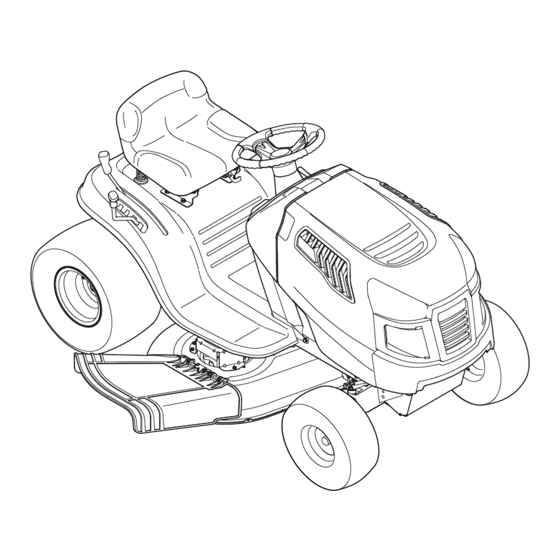
Operator's Manual
LAWN TRACTOR
7 Speed, Shift-on-the-Go
42" Deck
Model No. C459.60133
This product has a low emission engine which operates differently
from previously built engines. Before you start the engine, read and
understand this Operator's Manual.
CAUTION
Before using this equipment,
read this manual and follow
all safety rules and operating
instructions.
Sears Canada Inc., 290 Yonge Street, Toronto, On M5B 2C3
®
Visit our web site: sears.ca
Form No. 769-06861
(02.03.11)
Advertisement
Table of Contents

Subscribe to Our Youtube Channel
Related Manuals for Craftsman C459.60133


Summary of Contents for Craftsman C459.60133
- Page 1 Operator’s Manual ® LAWN TRACTOR 7 Speed, Shift-on-the-Go 42” Deck Model No. C459.60133 This product has a low emission engine which operates differently from previously built engines. Before you start the engine, read and understand this Operator’s Manual. CAUTION Before using this equipment,...
- Page 2 TABLE OF CONTENTS Safety Instructions ......3-6 Parts List (Rider) ......30-43 Safety Labels .
- Page 3 SAFETY INSTRUCTIONS WArNINg DANger This machine was built to be operated according to the safe opera- This symbol points out important safety instructions which, if not tion practices in this manual. As with any type of power equipment, followed, could endanger the personal safety and/or property of carelessness or error on the part of the operator can result in serious yourself and others.
- Page 4 SAFETY INSTRUCTIONS SlOpe OperATION • Slow down before turning. Operate the machine smoothly. Avoid erratic operation and excessive speed. Slopes are a major factor related to loss of control and tip-over • Disengage blade(s), set parking brake, stop engine and wait until accidents which can result in severe injury or death.
- Page 5 SAFETY INSTRUCTIONS CHIlDreN SerVICe Tragic accidents can occur if the operator is not alert to the presence Safe Handling of Gasoline of children. Children are often attracted to the machine and the mowing To avoid personal injury or property damage use extreme care in activity.
- Page 6 SAFETY INSTRUCTIONS General Service • Do not change the engine governor settings or over-speed the engine. The governor controls the maximum safe operating speed • Never run an engine indoors or in a poorly ventilated area. Engine of the engine. exhaust contains carbon monoxide, an odorless, and deadly gas.
- Page 7 SAFETY INSTRUCTIONS SAfeTY SYMBOlS This page depicts and describes safety symbols that may appear on this product. Read, understand, and follow all instructions on the machine before attempting to assemble and operate. Symbol Description READ THE OPERATOR’S MANUAL(S) Read, understand, and follow all instructions in the manual(s) before attempting to assemble and operate DANGER—...
- Page 8 SAFETY INSTRUCTIONS SlOpe gUIDe...
- Page 9 SAFETY LABELS S32356...
- Page 10 ASSEMBLY IMPORTANT: Your tractor is shipped with motor oil in the engine. shipping Brace Removal However, you MUST check the oil level before operating. Refer to the WARNING Service & Maintenance section for instructions on checking the oil Make sure the riding mower’s engine is off, remove the ignition key, level.
- Page 11 ASSEMBLY Figure 3 Figure 4 Tire Pressure Place the steering wheel cap over the center of the steering wheel and push downward until it “clicks” into place. WARNING Attaching The Seat Maximum tire pressure under any circumstances is 30 psi. Equal If the seat for your tractor was not attached at the factory, refer to the tire pressure should be maintained at all times.
- Page 12 NOTE: Any reference in this manual to the RIGHT or LEFT side of the tractor is observed from operator’s seat position facing forward towards the front of tractor. Meets ANSI Safety Standards Craftsman Tractors conform to the safety standard of the American National Standards Institute (ANSI).
- Page 13 OPERATION SPEED CONtrOL LEvEr SHIFt LEvEr The speed control lever, located on the left side of the The shift lever is located on the left tractor’s dash console, allows you to regulate the ground side of the fender and has three speed of the lawn tractor.
- Page 14 OPERATION SAFEty INtErLOCk SyStEM Gas and Oil Fill-up The safety interlock system is designed for safe operation of the trac- tor. If this system should ever malfunction, do not operate the tractor. IMPORTANT: Your tractor is shipped with motor oil in the engine. Immediately contact 1-800-4-MY-HOME to have the system serviced.
- Page 15 OPERATION IGNItION SwItCH SEttING tHE CuttING HEIGHt The ignition switch is activated to start the engine. Insert key into the Select the height position of the cutting deck by placing the deck ignition switch and turn clockwise to the START position. Release the lift lever in any of the six different cutting height notches on the key into the ON position once engine has fired.
- Page 16 OPERATION StOPPING tHE ENGINE Place the shift lever in neutral, Engage the parking brake, wArNING Shut engine off and remove the key. Doing so will minimize the If you strike a foreign object, stop the engine, disconnect the spark possibility of having your lawn ‘‘browned’’ by hot exhaust from plug wire(s) and ground against the engine.
- Page 17 OPERATION MuLCHING HEADLIGHtS A mulch kit is available as an attachment. Mulching is a process of • The lamps are ON whenever the tractor’s engine is running. recirculating grass clippings repeatedly beneath the cutting deck. • The lamps turn OFF when the ignition key is moved to the STOP The ultra-fine clippings are then forced back into the lawn where position.
- Page 18 SERVICE AND MAINTENANCE MAINTENANCE SCHEDULE WARNING Before performing any type of maintenance/service, disengage all Follow the maintenance schedule given below. This chart describes controls and stop the engine. Wait until all moving parts have come to service guidelines only. Use the Service Log column to keep track a complete stop.
- Page 19 SERVICE AND MAINTENANCE eNgINe MAINTeNANCe Changing engine Oil The engine oil should be changed in the first 5 hours and then every 50 Checking the engine Oil hours or once a season. To change the engine oil, proceed as follows: Only use high quality detergent oil rated with API service classification With engine OFF but still warm, d isconnect spark plug wire and...
- Page 20 SERVICE AND MAINTENANCE fuel filter Air Cleaner WArNINg WArNINg If filters, or covers are not installed correctly serious injury or death Gasoline and its vapors are extremely flammable and explosive. Fire could result from backfire. Do not attempt to start the engine with or explosion can cause severe burns or death.
- Page 21 SERVICE AND MAINTENANCE lUBrICATION Spark plug Clean area around the spark plug base. Do not sandblast spark plug. WArNINg Spark plug should be cleaned by scraping or wire brushing and Before lubricating, repairing, or inspecting, always disengage PTO washing with a commercial solvent (Blade Engage Lever), move shift lever into neutral position, set Remove and inspect the spark plug.
- Page 22 SERVICE AND MAINTENANCE CleANINg THe eNgINe AND DeCk Measure the distance from the front of the blade tip to the ground and the rear of the blade tip to the ground. The first measure- Any fuel or oil spilled on the machine should be wiped off promptly. Do ment taken should be between ¼”...
- Page 23 SERVICE AND MAINTENANCE Hex Cap Screw Figure 17 Figure 16 Looking at the cutting deck from the left side of the tractor, locate Seat Adjustment the bow-tie pin that secures the deck support rod on the rear Refer to the Assembly section of this manual for seat adjustment left side of the deck.
- Page 24 SERVICE AND MAINTENANCE The recommended operating tire pressure is: Remove the bow-tie cotter pin securing the deck stabilizer rod to the deck. Slide the deck lift rod from the mounting bracket on the • Approximately 10 psi for the rear tires deck as seen in Fig.
- Page 25 SERVICE AND MAINTENANCE If your tractor has not been put into use for an extended period of time, Remove the hex flange nut that secures the blade to the spindle charge the battery as follows: assembly. See Fig. 21. Set your battery charger to deliver a max of 10 amperes. To properly sharpen the cutting blades, remove equal amounts of metal from both ends of the blades along the cutting edges, If your battery charger is automatic, charge the battery until the...
- Page 26 SERVICE AND MAINTENANCE IMPORTANT: The V-belt found on your tractor is specially designed While holding the belt and pulley together, rotate the pulley to the to engage and disengage safely. A substitute (non-OEM) V-belt can left. Continue holding and rotating the pulley and belt until the belt be dangerous by not disengaging completely.
- Page 27 OFF-SEASON STORAGE WArNINg Never store lawn tractor with fuel in tank indoors or in poorly ventilated areas where fuel fumes may reach an open flame, spark, or pilot light as on a furnace, water heater, clothes dryer, or gas appliance. prepArINg THe eNgINe DrAININg THe fUel Locate the fuel filter, which is located on the left side of the...
- Page 28 TROUBLESHOOTING WArNINg Before performing any type of maintenance/service, disengage all controls and stop the engine. Wait until all moving parts have come to a complete stop. Disconnect spark plug wire and ground it against the engine to prevent unintended starting. Always wear safety glasses during operation or while performing any adjustments or repairs.
- Page 29 Labels 777X44366 777X44365 LEFT RIGHT 777D15595 777X45089 777X44645 EMISSION CONTROL INFORMATION RENSEIGNEMENTS SUR LE CONTRÔLE DES ÉMISSIONS 777S32553 This equipment is soley for export and is therefore exempt under 40 CFR 1068.230 from U.S. emission standards and related requirements. Cet équipement est exclusivement destiné à l’exportation et, en fonction du règlement 40 DVR 1068.230, il n’est donc pas tenu de respecter les normes et autres exigences américaines annexes en matière d’émissions.
- Page 30 PARTS LIST Craftsman Model C459-60133...
- Page 31 PARTS LIST Craftsman Model C459-60133 Ref. Ref. Part No. Description Part No. Description 712-04065 Nut, Hex Flange Insert Lock, 3/8-16 925-1649 Bulb Socket 714-04040 Cotter Pin 683-04619-4043 Hood Assembly 783-06823 Speed Latch Support Tab 710-04484 Screw, 5/16-18 x .750 750-04465B...
- Page 32 PARTS LIST Craftsman Model C459-60133...
- Page 33 PARTS LIST Craftsman Model C459-60133 Ref. Ref. Part No. Description Part No. Description 725-04439 12v. Solenoid 683-04155A-0637 Shaft, Lift 756-04196A Engagement Pulley 712-04065 Nut, Hex Flange Insert Lock, 3/8-16 747-04857 Belt Keeper Rod Assembly 714-04040 Bow-Tie Pin, 91, RH 710-04484 Screw, Hd.
- Page 34 PARTS LIST Craftsman Model C459-60133...
- Page 35 PARTS LIST Craftsman Model C459-60133 Ref. Ref. Part No. Description Part No. Description 617-04094 Gear Assembly, Steering 683-0128B-0637 Pivot Bar Axle Assembly 710-0643 Screw, 5/16-18, 1.00, Gr5, Lock 710-04484 Screw, 5/16-18, 0.750 712-04065 Nut, Flange Lock, 3/8-16, GrF 710-1309 Screw, Mach, 5/16-18, 0.750 714-04039A Pin, Cotter, 5/32, 1.25...
- Page 36 PARTS LIST Craftsman Model C459-60133...
- Page 37 PARTS LIST Craftsman Model C459-60133 Ref. Part No. Description 710-0227 Screw, 8-18 x .500 710-04484 Screw, 5/16-18 x .750 712-04063 Flange Lock Nut, 5/16-18 720-04061 Knob, 3/8-16 x .875 925-1303 Outer Seat Spring 725-1439 Inner Seat Spring 726-0278 Insulator Boss Plate...
- Page 38 PARTS LIST Craftsman Model C459-60133...
- Page 39 PARTS LIST Craftsman Model C459-60133 Ref. Part No. Description 683-04549-0637 Muffler Shield Assembly 710-0227 Screw, AB #8-18 0.500 710-04683 Tap Screw, 3/8-16 1.000 710-0642 Tap Screw, 1/4-20 0.750 710-1314A Screw, Socket Head, 5/16-18 x .750 712-0271 Sems Nut, 1/4-20 BS-692236...
- Page 40 PARTS LIST Craftsman Model C459-60133...
- Page 41 PARTS LIST Craftsman Model C459-60133 Ref. Ref. Part No. Description Part No. Description 747-05188 Brake Rod 918-04566 Transmission Drive Assembly 747-05244 Shift Rod 647-04034C-0637 Pedal Assembly 647-04035 Shaft Lever Assembly 738-04237A Shoulder Screw, #10-32 x .500 750-0566A Spacer, .260 x .375 x 1.030 LG 710-0227 Screw, 8-18:0.500...
- Page 42 PARTS LIST Craftsman Model C459-60133...
- Page 43 PARTS LIST Craftsman Model C459-60133 Ref. Ref. Part No. Description Part No. Description 736-0362 Flat Washer, .330 x 1.25 x .06 918-04822A Spindle Pulley Assembly 738-04146 Bolt Plug, M16 x 1.5 683-0254B-0637 Deck Hanger Bracket Assembly 710-0642 Screw, 1/4-20 x .750 738-04162A Shoulder Spacer, .8840 x .190...
- Page 44 PARTS LIST Craftsman engine Model 31C707-3346-g2/g6 for Model C459-60133 1058 OPERATOR’S MANUAL 1329 REPLACEMENT ENGINE 1330 REPAIR MANUAL 48 SHORT BLOCK 1264 1263 1044 1270...
- Page 45 PARTS LIST Craftsman engine Model 31C707-3346-g2/g6 for Model C459-60133 1026 1022 1034 1029 1023 1022...
- Page 46 PARTS LIST Craftsman engine Model 31C707-3346-g2/g6 for Model C459-60133 1266 1091 1127...
- Page 47 PARTS LIST Craftsman engine Model 31C707-3346-g2/g6 for Model C459-60133 1036 EMISSIONS LABEL 1040 305A 305B 415A 1005 1044 1051...
- Page 48 PARTS LIST Craftsman engine Model 31C707-3346-g2/g6 for Model C459-60133 1054 1051 1090 1059 1119...
- Page 49 PARTS LIST Craftsman engine Model 31C707-3346-g2/g6 for Model C459-60133 121 CARBURETOR OVERHAUL KIT 1266 1266A 358 ENGINE GASKET SET 1022 1266 1095 VALVE GASKET SET 1022...
- Page 50 PARTS LIST Craftsman engine Model 31C707-3346-g2/g6 for Model C459-60133 Ref. Ref. Part No. Description Part No. Description 796010 Cylinder Assembly 694918 Pin-Float Hinge 696136 Valve-Float Needle 399265 Bushing/Seal Kit (Magneto Side) 391086s Seal-Oil (Magneto Side) 695419 Valve-Choke 697106 Sump-Engine 843099...
- Page 51 PARTS LIST Craftsman engine Model 31C707-3346-g2/g6 for Model C459-60133 Ref. Ref. Part No. Description Part No. Description 690323 Screw (Starter Motor) 697478 Link-Starter Switch 796308 Screen/Cup Assembly 691224 Clip-Wire 795315 Armature-Magneto 697128 Gear-Timing 691061 Screw (Magneto Armature) 793242 Link-Counterweight 491055s...
- Page 52 PARTS LIST Craftsman engine Model 31C707-3346-g2/g6 for Model C459-60133 Ref. Part No. Description 1059 698516 Kit-Screw/Washer (Alternator) 1090 691293 Retainer-Brush 1091 691333 Cap-Limiter 1095 794152 Gasket Set-Valve 1119 691183 Screw (Alternator) 1127 695407 Screw (Float Bowl) 1263 697124 Reed-Breather 1264...
- Page 53 WARRANTY STATEMENT General: Craftsman products are warranted to be free from defects in materials or workmanship for a specific time period as set-out below (the “Warranty Period”). Warranties extend to the original purchaser of a Craftsman product only. Purchases made through an online auction or through any website other than www.sears.ca are excluded.
- Page 54 look for relevant emissions Durability period and Air Index Information On Your engine emissions label Engines that are certified to meet the California Air Resources Board (CARB) Tier 2 Emission Standards must display information regarding the Emissions Durability Period and the Air Index. Sears, Roebuck and Co., U.S.A. makes this information available to the consumer on our emission labels.
- Page 55 (This page applicable in the U.S.A. and Canada only.) Sears Brands Management Corporation (Sears), the California Air resources Board (CArB) and the United States environmental protection Agency (U.S. epA) emission Control System Warranty Statement (Owner’s Defect Warranty rights and Obligations) EMISSION CONTROL WARRANTY COVERAGE IS APPLICABLE TO CERTI- YEAR 1997 AND LATER ENGINES WHICH ARE PURCHASED AND USED FIED ENGINES PURCHASED IN CALIFORNIA IN 1995 AND THEREAF-...
- Page 56 FEDERAL and/or CALIFORNIA EMISSION CONTROL WARRANTY STATEMENT YOUR WARRANTY RIGHTS AND OBLIGATIONS MTD Consumer Group Inc, the United States Environmental Protection Agency (EPA), and, for those products certified for sale in the state of California, the California Air Resources Board (CARB) are pleased to explain the emission (evaporative and/or exhaust) control system (ECS) warranty on your outdoor 2006 and later small off-road spark-ignited engine and equipment (outdoor equipment engine) In California, new outdoor equipment engines must be designed, built and equipped to meet the State’s stringent anti-smog standards (in other states, 1997 and later model year equipment must be designed, built, and equipped to meet the U.S.
- Page 57 The outdoor equipment engine owner will not be charged for diagnostic labor that is directly associated with diagnosis of a defec- tive, emission-related warranted part, provided that such diagnostic work is performed at a warranty station. MTD Consumer Group Inc is liable for damages to other engine or equipment components proximately caused by a failure under warranty of any warranted part.
- Page 58 REPAIR PROTECTION AGREEMENT Congratulations on making a smart purchase. Your new Craftsman® Once you purchase the Agreement, a simple phone call is all that it product is designed and manufactured for years of dependable opera- takes for you to schedule service. You can call anytime day or night, or tion.
- Page 59 02488 199260 07.21.05 BY Printed in U.S.A.
Need help?
Do you have a question about the C459.60133 and is the answer not in the manual?
Questions and answers