Table of Contents
Advertisement
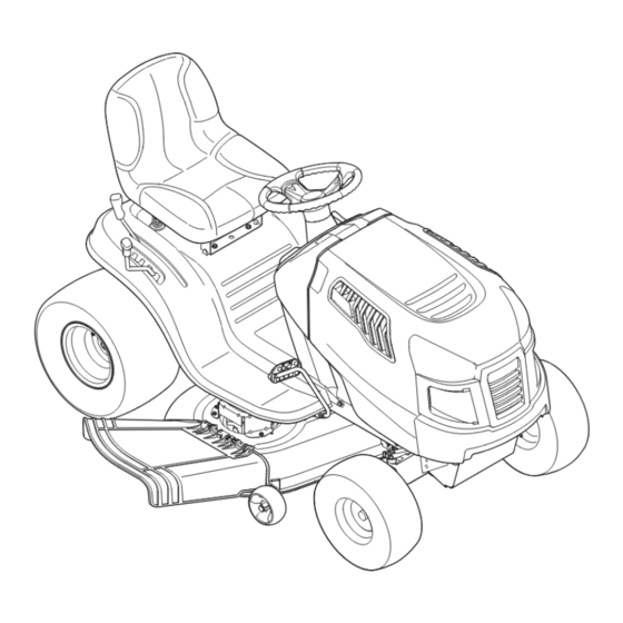
Operator's Manual
LAWN TRACTOR
21 HP, Variation Speed
46" Deck
Model No. C459.60102
This product has a low emission engine which operates differently
from previously built engines. Before you start the engine, read and
understand this Operator's Manual.
CAUTION
Before using this equipment,
read this manual and follow
all safety rules and operating
instructions.
Sears Canada Inc., 290 Yonge Street, Toronto, On M5B 2C3
®
Visit our web site: sears.ca
769-06863A
(01.31.11)
Advertisement
Table of Contents

Related Manuals for Craftsman C459.60102


Summary of Contents for Craftsman C459.60102
- Page 1 Operator’s Manual ® LAWN TRACTOR 21 HP, Variation Speed 46” Deck Model No. C459.60102 This product has a low emission engine which operates differently from previously built engines. Before you start the engine, read and understand this Operator’s Manual. CAUTION...
-
Page 2: Table Of Contents
TABLE OF CONTENTS Safety Instructions . . . . . . . . . . . . . . . . . . . . . . . . . 3-6 Parts List (Rider) . -
Page 3: Safety Instructions
SAFETY INSTRUCTIONS WArNINg DANger This machine was built to be operated according to the safe opera- This symbol points out important safety instructions which, if not tion practices in this manual. As with any type of power equipment, followed, could endanger the personal safety and/or property of carelessness or error on the part of the operator can result in serious yourself and others. - Page 4 SAFETY INSTRUCTIONS SlOpe OperATION • Slow down before turning. Operate the machine smoothly. Avoid erratic operation and excessive speed. Slopes are a major factor related to loss of control and tip-over • Disengage blade(s), set parking brake, stop engine and wait until accidents which can result in severe injury or death.
- Page 5 SAFETY INSTRUCTIONS CHIlDreN SerVICe Tragic accidents can occur if the operator is not alert to the presence Safe Handling of Gasoline of children. Children are often attracted to the machine and the mowing To avoid personal injury or property damage use extreme care in activity.
- Page 6 SAFETY INSTRUCTIONS General Service • Do not change the engine governor settings or over-speed the engine. The governor controls the maximum safe operating speed • Never run an engine indoors or in a poorly ventilated area. Engine of the engine. exhaust contains carbon monoxide, an odorless, and deadly gas.
- Page 7 SAFETY INSTRUCTIONS SAfeTY SYMBOlS This page depicts and describes safety symbols that may appear on this product. Read, understand, and follow all instructions on the machine before attempting to assemble and operate. Symbol Description READ THE OPERATOR’S MANUAL(S) Read, understand, and follow all instructions in the manual(s) before attempting to assemble and operate DANGER—...
- Page 8 SAFETY INSTRUCTIONS SlOpe gUIDe...
-
Page 9: Safety Labels
SAFETY LABELS ITeM TYpe : 4-purchd. S32356... -
Page 10: Assembly
ASSEMBLY IMPORTANT: Your tractor is shipped with motor oil in the engine. Shipping Brace removal However, you MUST check the oil level before operating. Refer to the WArNINg Service & Maintenance section for instructions on checking the oil Make sure the riding mower’s engine is off, remove the ignition key, level. - Page 11 ASSEMBLY Adjusting the Seat To adjust the position of the seat, pull up and hold the seat adjustment lever. Slide the seat forward or rearward to the desired position; then release the adjustment lever. Make sure seat is locked into position in a seat-stop before operating the tractor.
-
Page 12: Operation
NOTE: Any reference in this manual to the RIGHT or LEFT side of the tractor is observed from operator’s seat position facing forward towards the front of tractor. Meets ANSI Safety Standards Craftsman Tractors conform to the safety standard of the American National Standards Institute (ANSI). - Page 13 OPERATION pArkINg BrAke leVer AUTO-DrIVe peDAl To set the parking brake: Fully depress the brake pedal. Move the The drive pedal is located on the right side of the tractor, along the parking brake lever into the parking brake position. Release the brake running board.
- Page 14 OPERATION gAS AND OIl fIll-Up IMPORTANT: Your tractor is shipped with motor oil in the engine. However, you MUST check the oil level before operating. Be careful not to overfill. For instructions on how to check the engine oil, refer to Checking The Engine Oil in the Service and Maintenance section of this manual.
- Page 15 OPERATION SAfeTY INTerlOCk SYSTeM SeTTINg THe CUTTINg HeIgHT The safety interlock system is designed for safe operation of the trac- Select the height position of the cutting deck by placing the deck tor. If this system should ever malfunction, do not operate the tractor. lift lever in any of the different cutting height notches on the right Immediately contact 1-800-4-MY-HOME to have the system serviced.
- Page 16 OPERATION DrIVINg THe TrACTOr Turn the ignition key clockwise to the START position. After the engine starts, release the key. It will return to the ON (or Normal WArNINg Mowing) position. Avoid sudden starts, excessive speed and sudden stops. CAUTION WArNINg Do NOT hold the key in the START position for longer than ten seconds at a time.
- Page 17 OPERATION DrIVINg ON SlOpeS MOWINg Refer to the SLOPE GAUGE in the Safety Instructions section of the WArNINg manual to help determine slopes where you may operate this tractor To help avoid blade contact or a thrown object injury, keep bystand- safely.
-
Page 18: Service And Maintenance
SERVICE AND MAINTENANCE MAINTeNANCe SCHeDUle WArNINg Before performing any type of maintenance/service, disengage all Follow the maintenance schedule given below. This chart describes controls and stop the engine. Wait until all moving parts have come to service guidelines only. Use the Service Log column to keep track a complete stop. - Page 19 SERVICE AND MAINTENANCE eNgINe MAINTeNANCe Changing engine Oil The engine oil should be changed in the first 5 hours and then every Checking the engine Oil 50 hours or once a season. To change the engine oil, proceed as Only use high quality detergent oil rated with API service classification follows: SF, SG, SH, or SJ.
- Page 20 SERVICE AND MAINTENANCE fuel filter Air Cleaner WArNINg WArNINg If filters, or covers are not installed correctly serious injury or death Gasoline and its vapors are extremely flammable and explosive. Fire could result from backfire. Do not attempt to start the engine with or explosion can cause severe burns or death.
- Page 21 SERVICE AND MAINTENANCE Battery Porcelain Electrode The battery is sealed and is maintenance-free. Acid levels cannot be checked. • Always keep the battery cables and terminals clean and free of corrosive build-up. • After cleaning the battery and terminals, apply a light coat of petroleum jelly or grease to both terminals.
- Page 22 SERVICE AND MAINTENANCE Thread the hose coupler (packaged with your tractor’s Operator’s should be between ¼-inch and ³⁄8-inch lower than the rear of the deck. Manual) onto the end of your garden hose. Adjust if necessary as follows: Attach the hose coupler to the water port on your deck’s surface. With the tractor parked on a firm, level surface, place the lever See Figure 14.
- Page 23 SERVICE AND MAINTENANCE Hex Cap Screw Figure 17 Figure 16 WArNINg Retighten the hex cap screw on the left deck hanger bracket when proper adjustment is achieved. Avoid pinching injuries. Never place your fingers on the idler spring or Seat Adjustment between the belt and a pulley while removing the belt.
- Page 24 SERVICE AND MAINTENANCE The recommended operating tire pressure is: Remove the bow-tie cotter pin securing the deck stabilizer rod to the deck. Slide the deck lift rod from the mounting bracket on the • Approximately 10 psi for the rear tires deck as seen in Fig.
- Page 25 SERVICE AND MAINTENANCE If your tractor has not been put into use for an extended period of time, To properly sharpen the cutting blades, remove equal amounts charge the battery as follows: of metal from both ends of the blades along the cutting edges, parallel to the trailing edge, at a 25°- to 30°...
- Page 26 SERVICE AND MAINTENANCE pArkINg BrAke ADJUSTMeNT IMPORTANT: The V-belt found on your tractor is specially designed to engage and disengage safely. A substitute (non-OEM) V-belt can WArNINg be dangerous by not disengaging completely. For a proper working machine, use identical equipment belts as listed in the parts pages of Never attempt to adjust the brakes while the engine is running.
-
Page 27: Off-Season Storage
OFF-SEASON STORAGE WArNINg Never store lawn tractor with fuel in tank indoors or in poorly ventilated areas where fuel fumes may reach an open flame, spark, or pilot light as on a furnace, water heater, clothes dryer, or gas appliance. prepArINg THe eNgINe DrAININg THe fUel Locate the fuel filter, which is located on the left side of the... -
Page 28: Troubleshooting
TROUBLESHOOTING problem Cause remedy Engine fails to start PTO/Blade Engage lever engaged. Place lever in disengaged (OFF) position. Parking brake not engaged. Engage parking brake. Spark plug wire(s) disconnected. Connect wire(s) to spark plug(s). Throttle/Choke control lever not in correct Place Throttle/Choke lever into the FAST position. -
Page 29: Labels
Labels 777I22506 777I22508 777I22511 777X45093 Description Part #/N de pièce Supplier/Fournisseur Oil Filter / Filtre à huile 492932 Division 71, Source 500 Oil Capacity / Capacité d’huile 52 FL OZ/1.54L Division 71, Source 500 Air Filter / Filtre à air 793569 Division 71, Source 500 Pre Cleaner Element / Cartouche pré-filtre... -
Page 30: Parts List (Rider)
PARTS LIST Craftsman Model C459-60102... -
Page 31: Parts List (Engine)
PARTS LIST Craftsman Model C459-60102 Ref. Ref. Part No. Description Part No. Description 925-1649 Bulb Socket 783-06823 Speed Latch Support Tab 750-04465B Flange Spacer 683-04619-0691 Hood Assembly 783-04903A Speed latch 710-04484 Screw, 5/16-18 x .750 710-0599 Hex Washer Screw, 1/4-20 x .500... - Page 32 PARTS LIST Craftsman Model C459-60102...
- Page 33 PARTS LIST Craftsman Model C459-60102 Ref. Ref. Part No. Description Part No. Description 756-04196A Engagement Pulley 683-04334-0637 Shaft, Lift 683-04414-0637 Belt Keeper Rod Assembly 712-04065 Nut, Hex Flange Insert Lock, 3/8-16 710-04484 Screw, Hd. Tapp, 5/16-18 x .75 714-04040 Bow-Tie Pin, 91, RH...
- Page 34 PARTS LIST Craftsman Model C459-60102...
- Page 35 PARTS LIST Craftsman Model C459-60102 Ref. Ref. Part No. Description Part No. Description 617-04094 Gear Assembly, Steering 710-04484 Screw, 5/16-18, 0.750 710-0643 Screw, 5/16-18, 1.00, Gr5, Lock 712-04065 Nut, Flange Lock, 3/8-16, GrF 714-04039A Pin, Cotter, 5/32, 1.25 710-1309 Screw, Mach, 5/16-18, 0.750 914-0474 Pin, Cotter, 1/8 x 0.75...
- Page 36 PARTS LIST Craftsman Model C459-60102...
- Page 37 PARTS LIST Craftsman Model C459-60102 Ref. Part No. Description 710-04482 Hex Flange Bolt, 3/8-16 x .875 710-04484 Screw, Hd. Tapp, 5/16-18 x .75 712-3004A Flange Lock Nut, 5/16-18 925-05013 Seat Safety Switch 725-05277 Seat Jumper Harness (not shown) 926-0154 Push Mount Cable Tie 732-04035 Spring, Compress., 1.28 x 3.125...
- Page 38 PARTS LIST Craftsman Model C459-60102...
- Page 39 PARTS LIST Craftsman Model C459-60102 Ref. Part No. Description 683-04549-0637 Muffler Shield Assembly 710-0227 Screw, AB #8-18 0.500 710-04683 Tap Screw, 3/8-16 1.000 710-0642 Tap Screw, 1/4-20 0.750 710-1314A Screw, Socket Head, 5/16-18 x .750 712-0271 Sems Nut, 1/4-20 BS-692236...
- Page 40 PARTS LIST Craftsman Model C459-60102...
- Page 41 PARTS LIST Craftsman Model C459-60102 Ref. Part No. Description Ref. Part No. Description 731-04604 Sleeve, .758 X .821 X 2.4375 918-04566 Dr Assembly, Autodrive Lt-5 731-06330 Plug, Deck Hole, 7/8 683-04606 Auto-drive Bracket Assembly 731-06894 Shift Plate Bearing 683-04684 Idler Bracket Assembly 710-1260A Tap Screw, 5/16-18 x 0.750...
- Page 42 PARTS LIST Craftsman Model C459-60102...
- Page 43 PARTS LIST Craftsman Model C459-60102 Ref. Ref. Part No. Description Part No. Description 736-0262 Flat Washer, .385 X .870 X .092 918-04865A Spindle Assembly 936-0344 Flat Washer, .385 X 1.0 X .030 683-0254B-0637 Deck Hanger Bracket Assembly 736-0362 Flat Washer, .330 X 1.25 X .06 756-04356 Deck Pulley, 6.93 DIA...
- Page 44 PARTS LIST Craftsman engine Model 331877-0869-g5 for Model C459-60102 1330 REPAIR MANUAL 48 SHORT BLOCK 1058 OPERATOR’S MANUAL 1329 REPLACEMENT ENGINE 1264 1263 1270 1017 1027 1024...
- Page 45 PARTS LIST Craftsman engine Model 331877-0869-g5 for Model C459-60102 415A 186A 1022 1034 1029 1023 1022 1026...
- Page 46 PARTS LIST Craftsman engine Model 331877-0869-g5 for Model C459-60102 1091 1127 1266...
- Page 47 PARTS LIST Craftsman engine Model 331877-0869-g5 for Model C459-60102 1036 EMISSIONS LABEL 1040 1279 1265 305A 305B 187A 187B 1139 1005 1044 1051...
- Page 48 PARTS LIST Craftsman engine Model 331877-0869-g5 for Model C459-60102 1059 1119 1051 1090...
- Page 49 PARTS LIST Craftsman engine Model 331877-0869-g5 for Model C459-60102 121 CARBURETOR OVERHAUL KIT 1266 358 ENGINE GASKET SET 1022 1266 1095 VALVE GASKET SET 1022...
- Page 50 PARTS LIST Craftsman engine Model 331877-0869-g5 for Model C459-60102 Ref. Ref. Part No. Description Part No. Description 794128 Cylinder Assembly 695408 Kit-Idle Speed 399265 Bushing/Seal Kit (Magneto Side) 694918 Pin-Float Hinge 391086s Seal-Oil (Magneto Side) 696136 Valve-Float Needle 697188 Sump-Engine...
- Page 51 PARTS LIST Craftsman engine Model 331877-0869-g5 for Model C459-60102 Ref. Ref. Part No. Description Part No. Description 690323 Screw (Starter Motor) 697392 Pin-Counterweight 497608 Brush Set 796448 Retainer (Fuel Pump) 796309 Screen/Cup Assembly 693713 Gear-Pinion 795315 Armature-Magneto 698329 Harness-Wiring 691061...
- Page 52 PARTS LIST Craftsman engine Model 331877-0869-g5 for Model C459-60102 Ref. Part No. Description 1091 691333 Cap-Limiter 1095 794152 Gasket Set-Valve 1119 691183 Screw (Alternator) 1127 695407 Screw (Float Bowl) 1139 796449 Washer (Fuel Pump) 1263 697124 Reed-Breather 1264 697104 Screw (Breather Reed)
-
Page 53: Warranty Statement
WARRANTY STATEMENT General: Craftsman products are warranted to be free from defects in materials or workmanship for a specific time period as set-out below (the “Warranty Period”). Warranties extend to the original purchaser of a Craftsman product only. Purchases made through an online auction or through any website other than www.sears.ca are excluded. -
Page 54: Emisions Durability Period
look for relevant emissions Durability period and Air Index Information On Your engine emissions label Engines that are certified to meet the California Air Resources Board (CARB) Tier 2 Emission Standards must display information regarding the Emissions Durability Period and the Air Index. Sears, Roebuck and Co., U.S.A. makes this information available to the consumer on our emission labels. -
Page 55: Statement
(This page applicable in the U.S.A. and Canada only.) Sears Brands Management Corporation (Sears), the California Air Resources Board (CARB) and the United States Environmental Protection Agency (U.S. EPA) Emission Control System Warranty Statement (Owner’s Defect Warranty Rights and Obligations) EMISSION CONTROL WARRANTY COVERAGE IS APPLICABLE TO CERTI- YEAR 1997 AND LATER ENGINES WHICH ARE PURCHASED AND USED FIED ENGINES PURCHASED IN CALIFORNIA IN 1995 AND THEREAF-... -
Page 56: Statement
FEDERAL and/or CALIFORNIA EMISSION CONTROL WARRANTY STATEMENT YOUR WARRANTY RIGHTS AND OBLIGATIONS MTD Consumer Group Inc, the United States Environmental Protection Agency (EPA), and, for those products certified for sale in the state of California, the California Air Resources Board (CARB) are pleased to explain the emission (evaporative and/or exhaust) control system (ECS) warranty on your outdoor 2006 and later small off-road spark-ignited engine and equipment (outdoor equipment engine) In California, new outdoor equipment engines must be designed, built and equipped to meet the State’s stringent anti-smog standards (in other states, 1997 and later model year equipment must be designed, built, and equipped to meet the U.S. - Page 57 The outdoor equipment engine owner will not be charged for diagnostic labor that is directly associated with diagnosis of a defec- tive, emission-related warranted part, provided that such diagnostic work is performed at a warranty station. MTD Consumer Group Inc is liable for damages to other engine or equipment components proximately caused by a failure under warranty of any warranted part.
-
Page 58: Repair Protection Agreement
REPAIR PROTECTION AGREEMENT Congratulations on making a smart purchase. Your new Craftsman® Once you purchase the Agreement, a simple phone call is all that it product is designed and manufactured for years of dependable opera- takes for you to schedule service. You can call anytime day or night, or tion. - Page 59 02488 199260 07.21.05 BY Printed in U.S.A.
- Page 67 ENGINEERED TO PROVIDE OPTIMUM AIRFLOW TO LIFT GRASS AND PROVIDE A PRECISE CUT ÉTUDIÉ POUR PERMETTRE LA CIRCULATION OPTIMALE DE L ’ A IR POUR RELEVER LES BRINS D’HERBE ET ASSURER UNE COUPE IMPECCABLE.
Need help?
Do you have a question about the C459.60102 and is the answer not in the manual?
Questions and answers