Table of Contents
Advertisement
Quick Links
UM2743
User manual
Discovery kit for LTE Cat M/NBIoT with STM32L4 Series
Introduction
The
B-L462E-CELL1
Discovery kit is a turnkey development platform for cellular IoT devices. The Discovery kit contains a
low-power Discovery main board powered by an LBAD0ZZ1SE module, a global coverage antenna, and a fan-out board.
The LBAD0ZZ1SE module includes an
STM32L462REY6TR
microcontroller, an LBAD0XX1SC-DM ultra-small LTE Cat M/NB
modem, and an ST4SIM-200M GSMA-certified embedded SIM with a prepaid cellular connectivity data plane. ST4SIM-200M
can also be used as an embedded secure element (eSE) for application.
STMod+ and extended pins connectivity provide unlimited expansion capabilities with a large choice of specialized add-on
™
2
boards. Moreover, the fan-out board supports add-on boards using mikroBUS
, ESP‑01, Grove I
C, Grove UART, and
breadboard. The B-L462E-CELL1 Discovery kit includes an ST-LINK debugger/programmer and comes with the comprehensive
STM32Cube software libraries together with packaged software examples to demonstrate end-to-end connectivity.
This document provides information about the Discovery kit hardware features and instruction to run the demonstration
application software.
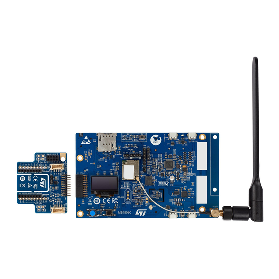
Figure 1.
B-L462E-CELL1 Discovery kit for IoT nodes
Picture is not contractual.
UM2743 - Rev 1 - March 2021
www.st.com
For further information contact your local STMicroelectronics sales office.
Advertisement
Table of Contents

Related Manuals for STMicroelectronics B-L462E-CELL1


Summary of Contents for STMicroelectronics B-L462E-CELL1
- Page 1 , ESP‑01, Grove I C, Grove UART, and breadboard. The B-L462E-CELL1 Discovery kit includes an ST-LINK debugger/programmer and comes with the comprehensive STM32Cube software libraries together with packaged software examples to demonstrate end-to-end connectivity. This document provides information about the Discovery kit hardware features and instruction to run the demonstration application software.
-
Page 2: Features
C interface (MAX9867ETJ+ from Maxim) • Ultra-low-power 3D accelerometer and 3D magnetometer (LSM303AGR) from STMicroelectronics • Capacitive digital sensor for relative humidity and temperature (HTS221) from STMicroelectronics • 260-1260 hPa absolute digital output barometer (LPS22HH) from STMicroelectronics • 3 user LEDs •... -
Page 3: Ordering Information
UM2743 Ordering information Ordering information To order the B-L462E-CELL1 Discovery kit for IoT nodes, refer to Table 1. Additional information is available from the datasheet and reference manual of the target STM32. Table 1. Ordering information Order code Board references Target STM32 •... -
Page 4: Development Environment
UM2743 Development environment Development environment The B-L462E-CELL1 Discovery kit for IoT nodes runs with the STM32L462RE 32-bit microcontroller based on the ® ® Cortex -M4 core. System requirements ® ® ® • Windows OS (7, 8, or 10), Linux 64-bit, or macOS ®... -
Page 5: Conventions
UM2743 Conventions Conventions Table 3 provides the conventions used for the ON and OFF settings in the present document. Table 3. ON/OFF convention Convention Definition Jumper JPx ON Jumper fitted Jumper JPx OFF Jumper not fitted Jumper JPx [1-2] Jumper fitted between Pin 1 and Pin 2 Solder bridge SBx ON SBx connections closed by 0 Ω... -
Page 6: Delivery Recommendations
UM2743 Delivery recommendations Delivery recommendations Before first use, check the board for any damage that might have occurred during shipment, that all socketed components are firmly fixed in their sockets and that none are loose in the plastic bag. UM2743 - Rev 1 page 6/58... -
Page 7: References
Murata provides access to documents and support from CatM1/NB-IoT Type1SE support site for customers who purchase Evaluation kits for the Type1SE family. Follow the instruction provided in the Murata Type1SE overview to access the mymurata website and use the code found on the B-L462E-CELL1 insert card. UM2743 - Rev 1 page 7/58... -
Page 8: Hardware Layout And Configuration
UM2743 Hardware layout and configuration Hardware layout and configuration The B-L462E-CELL1 Discovery kit for IoT nodes is designed around the LBAD0ZZ1SE Murata module. The hardware block diagram (Refer to Figure 2) illustrates the connection between LBAD0ZZ1SE and peripherals: OLED screen, sensors, USB FS connector, USARTs, audio, EEPROM, micro SIM card, and embedded ST-LINK/ V2-1. -
Page 9: Figure 3. B-L462E-Cell1 Discovery Kit For Iot Nodes (Top View)
Figure 3. B-L462E-CELL1 Discovery kit for IoT nodes (top view) USB PWR (CN11) USB ST-LINK (CN9) SIM card slot (CN2) Modem LED status (PSM and TX) Current measurement jumper (JP1) ST-LINK MCU (U12) LBAD0ZZ1SE (U5) 1.8V LDO (U19) User LED(LD1,LD2,LD3) -
Page 10: Figure 4. B-L462E-Cell1 Discovery Kit For Iot Nodes (Bottom View)
Figure 4. B-L462E-CELL1 Discovery kit for IoT nodes (bottom view) Pins to modem (CN13) Audio jack (CN14) Audio codec (U24) 3.3V LDO (U25) 3.6V LDO (U30) Battery case (BT1) EEPROM (U23) Level shifters (U27, U28, and U29) Pins to MCU (CN12) -
Page 11: Figure 5. B-L462E-Cell1 Discovery Kit For Iot Nodes Mechanical Drawing (Top View)
Figure 5. B-L462E-CELL1 Discovery kit for IoT nodes mechanical drawing (top view) -
Page 12: Figure 6. B-L462E-Cell1 Discovery Kit For Iot Nodes Mechanical Drawing (Bottom View)
Figure 6. B-L462E-CELL1 Discovery kit for IoT nodes mechanical drawing (bottom view) -
Page 13: Embedded Stlink/V2-1
In case the B-L462E-CELL1 Discovery kit for IoT nodes is connected to the PC before the driver is installed, some Discovery board interfaces may be declared as “Unknown” in the PC device manager. In this case, the user... -
Page 14: Target Voltage Level On Stm32Cubeprogrammer
Power supply The B-L462E-CELL1 Discovery kit for IoT nodes is designed to be powered by a 5 V DC power supply. It is possible to configure the B-L462E-CELL1 Discovery kit for IoT nodes to use any of the following five sources for the power supply: UartUsbVbus, Vbus, 5V_USB_CHG, 5V_USB_PWR, and EXT_BAT. -
Page 15: Figure 8. Power Tree
UM2743 Power supply Figure 8. Power tree 3.3 V LDO ST-LINK/V2-1 USB_ST_LINK LD3985M33R USB_UART USB_DEVICE USB_PWR LBAD0ZZ1SE Battery 3.6 V LDO 0.96-inch ST1L05BPUR OLED 1.8 V LDO Quad-SPI ST1L05BPUR Flash HTS221 SB34 SB33 1.8 V USB to UART 1V8_MD EEPROM VDDIO_MDM Audio codec LSM303AGR... -
Page 16: Clock Source
The other clock source is the 32.768 KHz in the module which is used to be the RTC clock source for the STM32L462RE microcontroller. Reset sources The reset signal of the B-L462E-CELL1 Discovery kit for IoT nodes is active LOW and the reset sources include: • A reset button B1 •... -
Page 17: 260 Hpa To 1260 Hpa Absolute Digital Output Barometer (Lps22Hh)
The device comprises a sensing element and an IC interface which communicates from the sensing element to the application through I C or SPI. On the B-L462E-CELL1 Discovery kit for IoT nodes, the I2C1 bus from STM32L462REY6TR is used. The sensing element, which detects absolute pressure, consists of a suspended membrane manufactured using a dedicated process developed by ST. -
Page 18: Capacitive Digital Sensor For Relative Humidity And Temperature (Hts221)
16-bit humidity and temperature output data • SPI and I C interfaces. On the B-L462E-CELL1 Discovery kit for IoT nodes, the I2C1 bus from STM32L462REY6TR is used. • Factory calibrated: Tiny 2 mm x 2 mm x 0.9 mm package ®... -
Page 19: Oled Screen
OLED screen 7.10 OLED screen 9OL9935701000 is a 0.96-inch OLED screen with the SSD1315Z driver IC. On the B-L462E-CELL1 Discovery kit for IoT nodes, the SPI3 bus from STM32L462REY6TR is used to connect this OLED screen. It has the following features: •... -
Page 20: Buttons And Leds
UM2743 Buttons and LEDs 7.12 Buttons and LEDs The B1 black button located on the top left side is the reset of the STM32L462REY6TR microcontroller. Refer to Figure The B2 blue button located on the top left side is used as a digital input or as an alternate wake-up function. When the button is depressed the logic state is LOW, otherwise, the logic state is HIGH. -
Page 21: Connectors
UM2743 Connectors Connectors Sixteen connectors are implemented on the B-L462E-CELL1 Discovery kit for IoT nodes: • CN1 SMA connector for antenna • CN2 SIM card slot • CN3 Tag connector • CN4 ST-LINK select jumper • CN5 ST-LINK debug connector •... -
Page 22: Sim Card Slot
SWD mode, which is shared with the same signals as ST-LINK. The TC2050-IDC-NL cable is used to link ST-LINK and tag connector on the B-L462E-CELL1 Discovery kit for IoT nodes, so that the STM32L4 in the module can be easily programmed and debugged without any extra accessory. -
Page 23: St-Link Select Jumper
UM2743 ST-LINK select jumper Figure 10. TC2050-IDC-NL cable Table 7. Tag connector pinout STM32L Connector Pin name Signal name Function number 4 pin 1.8V Power TMS/SWDIO TMS/SWDIO PA13 Serial wire data I/O Ground TCK/SWCLK TCK/SWCLK PA14 Serial wire clock Ground Serial wire output RESET# RESET#... -
Page 24: St-Link Debug Connector
UM2743 ST-LINK debug connector ST-LINK debug connector The ST-LINK debug connector is a 6-pin, 2.54 mm pitch male connector. It provides access to the embedded SWJ-DP interface of the STM32F103CBT6 MCU. This SWJ-DP interface is a combined JTAG and serial wire debug port that enables either a serial wire debug or a JTAG probe, to be connected to the target. -
Page 25: Usb Connector For The User Device
UM2743 USB connector for the user device USB connector for the user device This USB connector is used to connect the USB device port in the STM32L462REY6TR microcontroller. Refer to Figure 11 for pin‑number location. This USB connector can be used for communication with external-host USB. USB driver is delivered as part of STM32Cube MCU Package including CDC and mass-storage device classes. -
Page 26: Usb Connector For Uart
UM2743 USB connector for UART USB connector for UART This USB connector is used to connect the UARTs of the modem to debug and update the modem in LBAD0ZZ1SE. Refer to Figure 11 for pin‑number location. The user must refer to Murata documentation describing how to use the debug interface. Table 13. -
Page 27: Extension Pin Header For Mcu
This connector is a 50-pin, 2.54-mm pitch male connector. It is used to connect the MCU’s pins in the module. Table 15. Extension pin header for MCU How to disconnect with function Connector Pin number Signal name Function block on B-L462E-CELL1 board AVDD Power QUADSPI_IO1 USART2_CTS QUADSPI_IO0 USART2_RTS PB2_R... - Page 28 UM2743 Extension pin header for MCU How to disconnect with function Connector Pin number Signal name Function block on B-L462E-CELL1 board PA14 SWCLK LED1 PA15 SPI1_NSS PC7 is used on LBAD0ZZ1SE, it is not recommended to use PC7 as an...
-
Page 29: Extension Pin Header For Modem
UM2743 Extension pin header for modem 8.12 Extension pin header for modem This connector is a 50-pin, 2.54-mm pitch male connector. It is used to connect the modem pins in LBAD0ZZ1SE. Note that all signals that are started with FFU are not used with the current module version. Contact Murata to discuss any options. -
Page 30: Mm Stereo Headphone Connector
This headphone connector supports the CTIA standard which means the sequence of signals is Left, Right, GND and Mic. 8.14 Socket 10×2 STMod+ On the B-L462E-CELL1 Discovery kit for IoT nodes, the STMod+ connector provides flexibility in a small form factor application. The related STM32L462REY6TR I/Os for STMod+ are listed in Table 17. -
Page 31: Jumper Description
UM2743 Jumper description Connector Pin number Signal name Solder bridge STM32L4 pin Function PC1_C PH0_C RESET PC0_C ADC1_IN1 PC9_C TIM3_CH4 Power CN12 Power PA8_C PA5_C PA15_C PA15 PB14_C PB14 1. Default solder bridge state is shown in bold 8.15 Jumper description The STM32 current measurement can be done on JP1. -
Page 32: Cellular And End-To-End Data Plane Connectivity Setup
AT command. By default, the SIM selection policy is controlled by the software package provided by STMicroelectronics dedicated for this board and the user does not need to send explicitly an AT command. -
Page 33: Esim
UM2743 eSIM eSIM eSIM is the new standard in SIM technology, developed by the GSMA and already widely accepted by the telecoms market. eSIM is a smart, rewritable, and multi‑network SIM which is embedded into the module itself and allows to swap profiles without removing the SIM. -
Page 34: Figure 14. Terminal Console Showing Iccid
If the user accidentally overwrites or deletes the original pre-programmed application, he can still load a new application from B-L462E-CELL1 and retrieve a new version of the application related to this board. If such trace is no longer available with the newer application, or if the user wants to read ICCID at any time, he may... -
Page 35: Figure 16. Account Creation Screen
UM2743 eSIM ® Step 2: Connect to the Truphone web portal to activate the eSIM profile ® The user must connect to the Truphone web portal https://iot.truphone.com (using Chrome, Firefox, Safari, or Edge browser) and follow the provided instructions to create a user account if needed. Once logged in, the user can activate the SIM cards (eSIMs) right after completing registration as shown in Figure Figure 16. -
Page 36: Figure 18. Sim Description Details Screen
UM2743 eSIM Once the user enters the ICCIDs to activate, then the type of SIMs about to activate is presented. To proceed, the user clicks on continue Figure 18. SIM description details screen SIM includes a free 50‑Mbyte complementary data available for 90 days after activation Figure 19. -
Page 37: Figure 20. User Account Details
UM2743 eSIM Review the activation details and click Activate plan(s). Figure 20. User account details The activation of the SIM card may take a few minutes to complete and the SIM card status is shown on the IoT portal's dashboard once it is activated. Figure 21. -
Page 38: Embedded Secure Element
(Certificates and keys). The access to eSE is controlled and exposed via a software library provided by STMicroelectronics as part of the application software developed for the board. The eSE can be accessed at any time irrespective of the SIM slot that is used for the connectivity. Indeed, a plastic SIM card can be used for connectivity while eSE can still be used to access application credentials and related security services. -
Page 39: End-To-End Connectivity
UM2743 End-to-end connectivity End-to-end connectivity 9.4.1 End-to-end data transfer Once the cellular connectivity is activated and the device is registered on the network, the application pre- programmed on STM32 sends regularly (every 2 seconds) an echo message to an echo server located on the internet. -
Page 40: End-To-End Ping
UM2743 End-to-end connectivity 9.4.2 End-to-end ping When registered to the network, the user can verify the quality (latency, round-trip) of the end-to-end internet connectivity by sending ICMP ping to a server reachable via the internet. By default, the device pings the Google DNS server at 8.8.8.8. -
Page 41: Figure 25. Terminal Console Ping Command Statistics
UM2743 End-to-end connectivity The user can also check the statistics min/average/max round-trip of 10 pings and displayed on the terminal as shown in Figure Figure 25. Terminal console ping command statistics UM2743 - Rev 1 page 41/58... -
Page 42: B-L462E-Cell1 Board Information
UM2743 B-L462E-CELL1 board information B-L462E-CELL1 board information 10.1 Product marking The stickers located on the top or bottom side of the PCB provide product information: • Product order code and product identification for the first sticker • Board reference with revision, and serial number for the second sticker On the first sticker, the first line provides the product order code, and the second line the product identification. -
Page 43: Appendix A B-L462E-Cell1 Discovery Kit For Iot Nodes I/O Assignment
UM2743 B-L462E-CELL1 Discovery kit for IoT nodes I/O assignment Appendix A B-L462E-CELL1 Discovery kit for IoT nodes I/O assignment Note: The reader must refer to the latest version of the module datasheet to get the latest pin name. He can also use the latest version of the product specification from Murata. - Page 44 UM2743 B-L462E-CELL1 Discovery kit for IoT nodes I/O assignment Signal name of Discovery LBAD0ZZ1SE pin number Feature/comment LBAD0ZZ1SE pin name PCM_CLK PMU_AT_OUT PMU_VBACKUP PMU_AT_IN Anti-tamper PMU_AT_IN CLKOUT NC_RST FFU_GNSS_SFN_IND NC_PWR_BUTTON Module power VDD_MD Module power VDD_MD Module power VDD_MD FFU_PSM_IND...
- Page 45 UM2743 B-L462E-CELL1 Discovery kit for IoT nodes I/O assignment Signal name of Discovery LBAD0ZZ1SE pin number Feature/comment LBAD0ZZ1SE pin name SPI1_SCK PA5/SPI1_SCK SPI1_SCK SPI1_MOSI PB5/SPI1_MOSI SPI1_MOSI SPI1_MISO PB4/SPI1_MISO/NJTRST SPI1_MISO SPI1_NSS PA15/SPI1_NSS/JTDI SPI1_NSS PB3/TIM2_CH2/JTDO/ TIM2_CH2 TRACESWO D/C_DISP SPI3_MOSI SPI3_SCK eSIM_SWP SWP for NFC to ST33...
-
Page 46: Appendix Bstmod+Fan-Out Expansion Board
UM2743 STMod+fan-out expansion board Appendix B STMod+fan-out expansion board Refer to the user manual STMod+ fan-out expansion board for STM32 Discovery kits and Evaluation boards (UM2695). UM2743 - Rev 1 page 46/58... -
Page 47: Appendix C Antenna Parameters
UM2743 Antenna parameters Appendix C Antenna parameters Figure 26. Electrical and physical properties UM2743 - Rev 1 page 47/58... -
Page 48: Figure 27. S-Parameter Test
UM2743 Antenna parameters Figure 27. S-parameter test UM2743 - Rev 1 page 48/58... -
Page 49: Figure 28. Test Efficiency
UM2743 Antenna parameters Figure 28. Test efficiency UM2743 - Rev 1 page 49/58... -
Page 50: Appendix D Federal Communications Commission (Fcc) And Innovation, Science And Economic Development Canada (Ised) Compliance Statements
(2) this device must accept any interference received, including interference that may cause undesired operation. Part 15.21 Any changes or modifications to this equipment not expressly approved by STMicroelectronics may cause harmful interference and void the user's authority to operate this equipment. Part 15.105 This equipment has been tested and found to comply with the limits for a Class B digital device, pursuant to part 15 of the FCC Rules. -
Page 51: Ce / Red
équipement peut créer des interférences radio. Simplified CE declaration of conformity: ST Microelectronics hereby declares that the device B-L462E-CELL1 conforms with the essential requirements of Directive 2014/53/EU. The declaration of conformity can be found at www.st.com. UM2743 - Rev 1... -
Page 52: Revision History
UM2743 Revision history Table 19. Document revision history Date Revision Changes 23-Mar-2021 Initial release. UM2743 - Rev 1 page 52/58... -
Page 53: Table Of Contents
STMicroelectronics sensors........ - Page 54 B-L462E-CELL1 board information ........
- Page 55 UM2743 Contents Appendix C Antenna parameters ........... . .47 Appendix D Federal Communications Commission (FCC) and Innovation, Science and Economic Development Canada (ISED) Compliance Statements .
-
Page 56: List Of Tables
B-L462E-CELL1 Discovery kit for IoT nodes I/O assignment ....... . . -
Page 57: List Of Figures
Figure 5. B-L462E-CELL1 Discovery kit for IoT nodes mechanical drawing (top view) ......11 Figure 6. - Page 58 IMPORTANT NOTICE – PLEASE READ CAREFULLY STMicroelectronics NV and its subsidiaries (“ST”) reserve the right to make changes, corrections, enhancements, modifications, and improvements to ST products and/or to this document at any time without notice. Purchasers should obtain the latest relevant information on ST products before placing orders. ST products are sold pursuant to ST’s terms and conditions of sale in place at the time of order acknowledgement.
Need help?
Do you have a question about the B-L462E-CELL1 and is the answer not in the manual?
Questions and answers