Table of Contents
Advertisement
Quick Links
UM2271
User manual
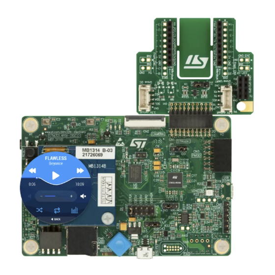
Discovery kit with STM32L4R9AI MCU
Introduction
The 32L4R9IDISCOVERY kit is a complete demonstration and development platform for the
®
®
STMicroelectronics Arm
Cortex
-M4 core-based STM32L4R9AI microcontroller.
Leveraging the innovative ultra-low power oriented features, 640 Kbytes of embedded RAM,
graphics performance (Chrom-ART Accelerator™) and DSI controller offered by the
STM32L4R9AI, the 32L4R9IDISCOVERY kit enables users to easily prototype applications
with state-of-the-art energy efficiency, as well as providing stunning audio and graphics
rendering with direct support for an AMOLED DSI round display. For even more user-
friendliness, the on-board ST-LINK/V2-1 debugger provides out-of-the-box programming
and debugging capabilities.
The STM32L4R9AI microcontroller features four I2Cs, five USARTs, one ULP UART, three
SPIs, two SAIs, one SDIO, one USB 2.0 full-speed OTG, two CANs, one FMC parallel
synchronous interface, one 12-bit ADC, one 12-bit DAC, two ULP analog comparators, two
op amps, one 2 data-lane DSI display, one digital filter for sigma delta modulator and SWP
interface, two Octo-SPI interfaces, 8- to 14-bit camera interface, one touch sensing
controller interface, JTAG and SWD debugging support.
This Discovery board offers everything required for users to get started quickly and develop
applications easily.The hardware features on the board help to evaluate the following
peripherals: USB OTG FS, microSD™ card, 8-bit camera interface, 16-Mbit PSRAM, PMOD
and STMod+ connectors, IDD measurement, full-duplex I2S with an audio codec and stereo
headset jack including an analog microphone, DFSDM with a pair of MEMS digital
microphones on board, 512-Mbit Octo-SPI Flash memory device, I2C extension connector,
1.2" AMOLED display using a one data-lane DSI interface with a capacitive touch panel.
The Arduino™ compatible connectors expand the functionality with a wide choice of
specialized shields. The integrated ST-LINK/V2-1 provides an embedded in-circuit
debugger and programmer for the STM32 MCU.
Figure 1. 32L4R9IDISCOVERY top view
Figure 2. 32L4R9IDISCOVERY bottom view
Pictures are not contractual
October 2017
DocID030906 Rev 2
1/78
www.st.com
1
Advertisement
Table of Contents

Related Manuals for STMicroelectronics 32L4R9IDISCOVERY


Summary of Contents for STMicroelectronics 32L4R9IDISCOVERY
- Page 1 UM2271 User manual Discovery kit with STM32L4R9AI MCU Introduction The 32L4R9IDISCOVERY kit is a complete demonstration and development platform for the ® ® STMicroelectronics Arm Cortex -M4 core-based STM32L4R9AI microcontroller. Leveraging the innovative ultra-low power oriented features, 640 Kbytes of embedded RAM, graphics performance (Chrom-ART Accelerator™) and DSI controller offered by the...
-
Page 2: Table Of Contents
Hardware layout and configuration ......11 10.1 32L4R9IDISCOVERY layout ........13 10.2 32L4R9IDISCOVERY mechanical drawing . - Page 3 10.13.1 32L4R9IDISCOVERY as USB device ......25 10.13.2 32L4R9IDISCOVERY as USB host ......26 10.14 Octo-SPI Flash memory .
- Page 4 Contents UM2271 Appendix E Fanout board (MB1280) ........71 MikroElektronika mikroBUS™...
- Page 5 SW1 switch setting ............18 Table 4. 32L4R9IDISCOVERY power sources configuration ......19 Table 5.
- Page 6 32L4R9IDISCOVERY STMOD+ interface ........
-
Page 7: Features
UM2271 Features Features • STM32L4R9AI Arm-based microcontroller with 2-Mbyte Flash memory and 640-Kbyte RAM in UFBGA169 package ® • 1.2" 390x390 pixel AMOLED round display panel with 16 million colors depth, MIPI interface and capacitive touch panel • USB OTG FS •... -
Page 8: System Requirements
The latest versions of the demonstration source code and associated documentation can be downloaded from the www.st.com/stm32l4-discovery web page. Ordering information To order the 32L4R9IDISCOVERY kit, refer to Table a. On Windows only 8/78 DocID030906 Rev 2... -
Page 9: Technology Partners
UM2271 Technology partners Table 1. Ordering information Order code Target STM32 STM32L4R9I-DISCO STM32L4R9AII6 Technology partners MACRONIX: 512-Mbit Octo-SPI NOR Flash memory device, part number MX25LM51245GXDI00 GOVISIONOX OPTOELECTRONICS: 1.2 inch 390x390 AMOLED display, part number G1120TB103GF-001 DocID030906 Rev 2 9/78... -
Page 10: Bootloader Limitations
Bootloader version is identified by reading the bootloader ID at the address 0x1FFF6FFE. Its value is 0x91 for bootloader V9.1 and 0x92 for V9.2. The STM32L4R9AII6 part soldered on the 32L4R9IDISCOVERY main board is marked with a date code corresponding to its date of manufacturing. STM32L4R9AII6 parts with a date code prior or equal to week 37 of 2017 are fitted with bootloader V9.1 affected by the... -
Page 11: Amoled Display Limitation
C extension connector, Arduino Uno shields and embedded ST-LINK). Figure 4 Figure 5 help the user to locate these features on the board. Mechanical drawing for 32L4R9IDISCOVERY and round DSI display boards is described in Figure DocID030906 Rev 2 11/78... -
Page 12: Figure 3. Hardware Block Diagram
Hardware layout and configuration UM2271 Figure 3. Hardware block diagram 12/78 DocID030906 Rev 2... -
Page 13: 32L4R9Idiscovery Layout
UM2271 Hardware layout and configuration 10.1 32L4R9IDISCOVERY layout Figure 4. 32L4R9IDISCOVERY top side layout DocID030906 Rev 2 13/78... -
Page 14: Figure 5. 32L4R9Idiscovery Bottom Side Layout
Hardware layout and configuration UM2271 Figure 5. 32L4R9IDISCOVERY bottom side layout 14/78 DocID030906 Rev 2... -
Page 15: 32L4R9Idiscovery Mechanical Drawing
10.2 32L4R9IDISCOVERY mechanical drawing Figure 6. 32L4R9IDISCOVERY mechanical drawing (top view, in mm) Legend: = Indicates the mounting hole between the 32L4R9IDISCOVERY board (at the top of Figure 6) and the round DSI display board (at the bottom of Figure... -
Page 16: Embedded St_Link/V2-1
Plastic spacer height = 13 mm, overall height = 26 mm ± 1 mm 10.3 Embedded ST_LINK/V2-1 The ST-LINK/V2-1 programming and debugging tool is integrated on the 32L4R9IDISCOVERY board. Compared to ST-LINK/V2, the changes are listed below: • new features supported on ST-LINK/V2-1: –... -
Page 17: Drivers
UM2271 Hardware layout and configuration 10.3.1 Drivers Before connecting the 32L4R9IDISCOVERY to a Windows (7, 8, 10) PC via USB, a driver for ST-LINK/V2-1 must be installed. It is available on the www.st.com website. If 32L4R9IDISCOVERY is connected to the PC before the driver is installed, some interfaces of the board may be declared as ‘Unknown’... -
Page 18: Tag And Swd
VDD_STL gets power from external through CN5. ST-LINK is then usable to program an external MCU. SW1 is accessible on bottom side of 32L4R9IDISCOVERY. By default, SW1 is in On position. To put micro switch in Off position, just push away the switch from ON position as... -
Page 19: Power Supply
Power supply 10.6.1 Power supply sources 32L4R9IDISCOVERY is designed to be powered by +5 V DC power supply. It is possible to configure the 32L4R9IDISCOVERY to use any of the sources listed in Table By default, the JP4 header must have a jumper on (1) STLK and SW1 is placed in ON position. -
Page 20: Table 5. Jp4: Power Source Selector Setting
CHGR: 5 V from 5 V DC power charger connected to USB STLINK (CN13). In this case, if 32L4R9IDISCOVERY is powered by an external USB charger, then the debug on CN13 is not available. When CHGR input is chosen, it is not recommended to connect a PC on USB STLINK, because the 500 mA limitation is no more effective and this may damage the PC. -
Page 21: Mcu Power Supply Options
10.6.2 MCU power supply options 32L4R9IDISCOVERY offers possibility to supply the MCU under 1.8 V or 3.3 V. The JP7 jumper must be placed on +3V3 to supply the MCU with 3.3 V, connecting pins 1 and 2. The jumper can be placed on +1V8 of JP7 to supply the MCU with 1.8 V, connecting... -
Page 22: Measurement Of Mcu Current Consumption
625 mA, in case a short circuit occurs on the board (the red LED fault LD5 lights on). 32L4R9IDISCOVERY can also be supplied by STLINK USB power source with no enumeration, such as a USB charger. In this particular case, the SB36 solder bridge must be closed. -
Page 23: Program Or Debug When Power Supply Not From St-Link/V2-1
STM32L4R9AI HSE input. Please refer to Appendix B: Solder bridges. 10.8 Reset Source The general reset of 32L4R9IDISCOVERY is active low. The reset sources are listed below: • Reset button B1 • Embedded ST-LINK/V2-1, SW1 micro-switch set to On (default setting) •... -
Page 24: Boot Configuration
Two ST-MEMS MP34DT01TR digital microphones U1 and U2 are available on 32L4R9IDISCOVERY. The two microphones are located at a distance of 21 mm from each other. They are connected to the STM32 DFSDM by the PC2 port, generating the clock, and... -
Page 25: Psram
A green LED LD6 is lit in one of the following cases: • Power switch (U16) is On and 32L4R9IDISCOVERY works as a USB host • VBUS is powered by another USB host when 32L4R9IDISCOVERY works as a USB device. The red LED LD7 is lit when over-current occurs. 10.13.1... -
Page 26: 32L4R9Idiscovery As Usb Host
A 512-Mbit Octo-SPI user Flash memory (MX25LM51245GXDI00 from MACRONIX) is connected to OCTOSPIM_P2 interface of STM32L4R9AI. By default, OCTOSPI_RESET of Flash memory has been connected to the general reset of 32L4R9IDISCOVERY. Appendix B: Solder bridges for possible Octo-SPI Flash configuration change. -
Page 27: Table 11. Ld1 And Ld2 Details
MCU port control color PB0 (MFX_GPIO0 from MFX) Orange PH4 (from main MCU) Green Other LEDs are present on the 32L4R9IDISCOVERY. Find below a summary list of all buttons and LEDs, with their description. Table 12. Buttons and LEDs Reference Color Function... -
Page 28: Connectors
11.1 Arduino connectors CN10, CN11, CN16 and CN17 CN10, CN11, CN16 and CN17 are female connectors compatible with Arduino Uno Revision 3 standard. Most of shields designed for Arduino can fit to 32L4R9IDISCOVERY board. Table 13. Arduino compatible connectors Left connectors Right connectors CN No. -
Page 29: Table 14. Jp3, Vdda And Vddusb, Settings
Connectors 1. The 3V3 on ARD connector PIN4 is not a power input for 32L4R9IDISCOVERY board, to simplify power architecture. 2. The external voltage applied to pin VIN should be in the range 6 to 9V at 25°C ambient temperature. If a higher voltage is applied on the regulator U15, it may overheat and could be damaged. -
Page 30: Dsi Display, Backlight And Touch Panel Connector Cn4
Connectors UM2271 11.2 DSI display, backlight and touch panel connector CN4 All the necessary signals to interface with round DSI display board are available through the DSI V3 connector CN4. Figure 10. DSI display connector CN4 Table 15. DSI display connector CN4 CN6 pin Function GPIO port... - Page 31 UM2271 Connectors Table 15. DSI display connector CN4 (continued) CN6 pin Function GPIO port Signal name Signal name GPIO port Function number Power output SPI2_SCK PB13 SPI clock SPI2_MOSIp PB15 SPI data SM3321 ground BLGND SPI_DCX PB14 data/control SM3321 ground BLGND RESERVED 3V3 voltage...
-
Page 32: Dsi Amoled Display
MB1314. The DSI interface of MB1314 is only one data-lane width and a clock lane, but the 32L4R9IDISCOVERY board supports DSI displays with up to two data-lane width. The DSI_V3 connector interface also enables the use of dedicated low power modes of display, thanks to the available SPI2 interface (MB1314 does not use it). -
Page 33: Usb Otg Fs Connector Cn9
UM2271 Connectors Touch panel interrupt output DSI_TOUCH_INT is connected to MFX_GPIO9. It is used as touch panel detection indication. MFX_GPIO10 resets capacitive touch panel and DSI display. 11.3 USB OTG FS connector CN9 An USB OTG full speed communication link is available at USB Micro AB receptacle connector CN9. -
Page 34: Microsd Card Connector Cn6
Connectors UM2271 Figure 12. USB Micro-B connector CN13 Table 17. USB Micro-B connector CN13 Pin number Description Pin number Description VBUS (power) Shield 11.5 microSD card connector CN6 microSD cards with 4 GBytes or more capacity are inserted in the receptacle CN6. Four data bits of the SDMMC1 interface, CLK and CMD signals of the STM32L4R9AI are used to communicate with the microSD card at +3V3 only. -
Page 35: Stmod+ Connector Cn1
11.6 STMod+ connector CN1 The standard 20-pin STMod+ connector is available on 32L4R9IDISCOVERY board to increase compatibility with external boards and modules from the Ecosystem of microcontrollers. By default, it is designed to support an ST dedicated Fanout board which allows connecting different modules or board extensions from different manufacturers. -
Page 36: Table 19. Stmod+ Connector Cn1
Connectors UM2271 please refer to ST Fanout board user manual and to relevant datasheets of associated modules. For details about STMod+ interface, please refer to STMod+ connector interface specification. Figure 14. STMod+ connector CN1 Table 19. STMod+ connector CN1 Description Description number number... -
Page 37: Pmod Connector Cn3
UM2271 Connectors Table 20. Quad SPDT switch configuration (continued) Pin number UART / SPI UART STMod+ pin 3 SPI2_MISOp USART3_RX USART3_RX STMod+ pin 4 SPI2_SCK SPI2_SCK USART3_RTS 1. UART / SPI defines default configuration for STMOD+_SEL_0 and STMOD+_SEL_1. Please, take care that this connector shares many GPIOs with other functions on the Board: for more detailed information please refer to Appendix A: GPIO assignment and sharing. -
Page 38: Camera Module Connector Cn2
Connectors UM2271 In order to be able to support selection of SPI or UART functions connection on PMOD by software, a quad SPDT switch has been added on board. It is controlled by two GPIOs from MFX_V3 circuit and enables MCU signal choice for pins 2, 3 and 4: refer to Table 20 STMod+ chapter for switch description details (pin 1, 2, 3 and 4 of PMOD are common with STMod+). -
Page 39: Tag Connector Cn8
UM2271 Connectors Table 22. Camera module connector CN2 (continued) Pin number Description Pin number Description DCMI_D6 (PB8) DCMI_PWR_EN (MFX_GPIO12) DCMI_D7 (PI7) DCMI_NRST (NRST from MCU) I2C1_SDA (PG13) I2C1_SCL (PB6) DCMI_PIXCK (PH5) 11.9 TAG connector CN8 The TAG connector footprint CN8 is used to connect STM32L4R9AI microcontroller for programming or debugging the board. -
Page 40: Ext_I2C Connector Cn7
Connectors UM2271 Table 24. SWD header CN5 Pin number Description Pin number Description SWDIO (PA13) SWCLK (PA14) NRST SWO (PB3) 11.11 EXT_I2C connector CN7 The EXT_I2C connector socket is used to connect external modules to I2C1 interface or to monitor the I2C1 interface. Figure 18. -
Page 41: Stereo Headset And Headphone Jack Cn12
UM2271 Connectors 11.12 Stereo headset and headphone jack CN12 A stereo headphone or a stereo headset with analog microphone is pluggable into the 3.5 mm standard jack socket CN12. Figure 19. Stereo headset with microphone jack CN12 Table 27. Audio jack connector CN12 Pin number Description Stereo headset with microphone pinning... -
Page 42: Appendix A Gpio Assignment And Sharing
Appendix A GPIO assignment and sharing Table 28. 32L4R9IDISCOVERY GPIO assignment and sharing GPIO port GPIO primary interface STMod+ interface PMOD interface ARDUINO interface ARD_A4 (ADC1_IN5) ARD_D5 (TIM5_CH2) STLINK_USART2_TX STLINK_USART2_RX DCMI_HSYNC/DE STMod+_ADC (ADC_1_IN9) ARD_D7 STMod+_PWM (TIM2_CH1) ARD_A5 (ADC1_IN10) PMOD_SPI2_CS //... - Page 43 Table 28. 32L4R9IDISCOVERY GPIO assignment and sharing (continued) GPIO port GPIO primary interface STMod+ interface PMOD interface ARDUINO interface JTDO/TRACESWO ARD_D6 (TIM3_CH1) SAI1_SD_B I2C1_SCL PSRAM_NL (ADV) (NU) DCMI_D6 SAI1_FS_A (NU) PB10 DSI_USART3_TX STMod+_USART3_TX PMOD_USART3_TX PB11 STMod+_USART3_RX PMOD_USART3_RX (NU) PB12 DFSDM_1_DATIN1...
- Page 44 Table 28. 32L4R9IDISCOVERY GPIO assignment and sharing (continued) GPIO port GPIO primary interface STMod+ interface PMOD interface ARDUINO interface PC13 JOY_SEL // WAKEUP PC14-OSC32_IN PC14-OSC32_IN PC15- PC15-OSC32_OUT OSC32_OUT PSRAM_D2 PSRAM_D3 SDMMC_1_CMD PSRAM_CLK PSRAM_NOE PSRAM_NWE PSRAM_NWAIT PSRAM_NE1 PSRAM_D13 PSRAM_D14 PD10 PSRAM_D15...
- Page 45 Table 28. 32L4R9IDISCOVERY GPIO assignment and sharing (continued) GPIO port GPIO primary interface STMod+ interface PMOD interface ARDUINO interface SAI1_SCK_A SAI1_SD_A PSRAM_D4 PSRAM_D5 PSRAM_D6 PE10 PSRAM_D7 PE11 PSRAM_D8 PE12 PSRAM_D9 PE13 PSRAM_D10 PE14 PSRAM_D11 PE15 PSRAM_D12 PSRAM_A0 PSRAM_A1 PSRAM_A2 PSRAM_A3...
- Page 46 Table 28. 32L4R9IDISCOVERY GPIO assignment and sharing (continued) GPIO port GPIO primary interface STMod+ interface PMOD interface ARDUINO interface PSRAM_A12 PSRAM_A13 PSRAM_A14 PSRAM_A15 ARD_D4 STMod+_I2C3_SCL ARD_D15 (I2C3_SCL) STMod+_I2C3_SDA ARD_D14 (I2C3_SDA) OCTOSPIM_P2_IO6 PG10 OCTOSPIM_P2_IO7 PG11 ARD_D2 PG12 OCTOSPIM_P2_NCS PG13 I2C1_SDA PG15...
- Page 47 Table 28. 32L4R9IDISCOVERY GPIO assignment and sharing (continued) GPIO port GPIO primary interface STMod+ interface PMOD interface ARDUINO interface (NU) PH14 DSI_SPI_USART_CS PH15 ARD_D8 ARD_D10 (SPI2_NSS_TIM5_CH4) MFX_INT_IN STMod+_SPI2_MISOs STMod+_SPI2_MOSIs DCMI_D5 DCMI_VSYNC/RDY OCTOSPIM_P2_CLK DCMI_D7 STMod+_RST PMOD_RST OCTOSPIM_P2_IO2 PI10 OCTOSPIM_P2_IO1 PI11 OCTOSPIM_P2_IO0...
-
Page 48: Table 29. Mfx_V3 Gpio Assignment (Lqfp48)
Table 29. MFX_V3 GPIO assignment (LQFP48) GPIO port Implemented functions Application function name PA0-WKUP MFX_aGPIO1 MFX_aGPIO1 MFX_aGPIO2 DSI_1V8_PWRON Reserved DAC_Out1 SPARE MFX_GPIO5 µSD_DETECT MFX_GPIO6 STMOD+_SEL_0 MFX_GPIO7 STMOD+_SEL_1 MFX_GPIO8 DSI_3V3_PWRON MFX_GPIO9 DSI_TOUCH_INT PA10 MFX_GPIO10 DSI_RESET PA11 MFX_GPIO11 EXT_RESET PA12 MFX_GPIO12 DCMI_PWR_EN PA13 MFX_SWDIO MFX_SWDIO... - Page 49 Table 29. MFX_V3 GPIO assignment (LQFP48) (continued) GPIO port Implemented functions Application function name MFX_IRQ_OUT MFX_IRQ_OUT PB10 PB11 PB12 MFX_IDD_MEAS IDD_MEAS PB13 MFX_GPIO13 USB_OTGFS_PPWR_EN PB14 MFX_GPIO14 USB_OVER PB15 MFX_GPIO15 AUDIO_Codec_RESET PC13-ANTI_TAMP MFX_WAKEUP MFX_WAKEUP PC14-OSC32_IN MFX_IDD_CAL PC15-OSC32_OUT MFX_IDD_SH0 PH0-OSC_IN MFX_IDD_SH1 PH1-OSC_OUT MFX_IDD_SH2...
-
Page 50: Appendix B Solder Bridges
Following Table 30 describes each solder bridge. The default state is indicated in bold. ON state means a 0 ohm resistor is soldered. OFF state means SBxx is open. Table 30. 32L4R9IDISCOVERY solder bridges Solder bridges State Description Enables ARD Green LED control by ARD_D13... - Page 51 Table 30. 32L4R9IDISCOVERY solder bridges (continued) Solder bridges State Description SB5 (RESERVED) Reserved, do not modify (PSRAM) SB14 (RESERVED) Reserved, do not modify (STLINK) SB9, SB10, SB11, SB12 Reserved, do not modify (display) (RESERVED) SB15 (RESERVED) Reserved, (USB OTG FS)
-
Page 52: Appendix C Stmod+ Gpio Sharing And Multiplexing
Appendix C STMod+ GPIO sharing and multiplexing Table 31. STMod+ GPIO sharing and multiplexing Shared or exclusive functions STMod+ Shared or exclusive functions PMOD Some other Alternate Functions Basic Port Pins Port Basic Some other Alternate Functions PMOD CTSS3 / CTSS3 / LCTS1 / T3.1 / T16.1 / [OP2_I+ / AD1.11] SA2.MCKA / DF1.C3 / T3.1 / T8.1... -
Page 53: Table 32. Spdt Quad Switch
UM2271 STMod+ GPIO sharing and multiplexing Table 32. SPDT quad switch UART / SPI UART STMOD+_SEL_0 STMOD+_SEL_0 is GPIO6 of MFX_V3 STMOD+_SEL_1 STMOD+_SEL_1 is GPIO7 of MFX_V3 pin 1 CSN2 CSN2 CTS3 pin 1 is connected directly to PA6 pin 2 MOSI2 TXS3 TXS3... -
Page 54: Appendix D Schematics
Schematics UM2271 Appendix D Schematics This section provides design schematics for the 32L4R9IDISCOVERY board and design schematics of the round DSI display and Fanout boards: Appendix D contains the schematics diagrams listed below: • Figure 20: 32L4R9IDISCOVERY board interconnections (MB1311C) •... - Page 55 Figure 20. 32L4R9IDISCOVERY board interconnections (MB1311C) ST_LINK PSRAM ST_LINK_V2-1_2.SCHDOC MCU.SchDoc PSRAM.SchDoc SWCLK SWCLK PSRAM PSRAM SWDIO SWDIO NRST OCTOSPI NRST RESET OCTOSPI.SchDoc USART_TX USART_TX OCTOSPI Flash OCTOSPI Flash NRST NRST USART_RX USART_RX NRST MCO_STLINK HSE_STLINK Peripherals STMOD+ Peripherals.SchDoc STMOD+.SchDoc EXT_RESET...
- Page 56 Figure 21. 32L4R9IDISCOVERY power U5V_ST_LINK Green ESDA7P60-1U1M Header M Straight 5x2H ARD_5V 5V_USB_CHARGER LD1117S50TR Vout ARDUINO power pin 10uF 10uF +3V3 2.2uH VSEL1 4.7uF VSEL2 10uF VSEL3 TPS62743 +1V8 2.2uH VSEL1 4.7uF VSEL2 10uF VSEL3 TPS62743 Title: Power Project: STM32L4R9I-DISCO...
- Page 57 Figure 22. 32L4R9IDISCOVERY Arduino Uno V3 connectors Arduino uno connector Green +3V3 ARD_D15 I2C3_SCL BSN20 ARD_D14 I2C3_SDA VREF+ WARNING: Some Arduino IOs are shared with other functions: SB27 ARD_5V +3V3 CN10 Following ARD signals are multiplexed or shared with other functions. In case ARDUINO...
- Page 58 Figure 23. 32L4R9IDISCOVERY ST-LINK/V2-1 R103 [N/A] SWCLK SWDIO R104 R105 +3V3_ST_LINK LED_STLINK STM_JTCK STM_JTMS LD3985M33R 5V_STL +3V3_ST_LINK BAT60JFILM Vout +3V3_ST_LINK VUSB_ST_LINK BAT60JFILM [N/A] SB36 BYPASS +3V3_ST_LINK CN15 [N/A] 100nF 100nF 100nF 100nF [N/A] R106 Not Fitted, must be on a border or the PCB.
- Page 59 Figure 24. 32L4R9IDISCOVERY Octo-SPI Flash memory Macronix MX25LM51245GXDI00 used by default (functional at 3V3 only) ECS feature can be monitored on Macronix by soldering SB25 RESET pins of Flash have internal pull-up (both) by default Double footprint to be compatible with Micron P/N...
- Page 60 Figure 25. 32L4R9IDISCOVERY peripherals I2C1_SCL RESET The 2 LEDs are top side EXT_I2C I2C1_SDA +3V3 TD-0341X-A00 [RESET/Black] Green LED_GREEN ESDA6V1L I2C1_SDA R108 PG13 Orange MFX_GPIO0 I2C1_SCL R107 R112 MFX_GPIO11 LED_ORANGE EXT_RESET SB37 F206A-2*04MGF-A SSM-104-L-DH (Samtec) PC13 - WKUP2 JOY_SEL Reset Button...
- Page 61 Figure 26. 32L4R9IDISCOVERY USB OTG FS MFX_GPIO14 USB_OTGFS_OVRCR USB_OVER +3V3 FAULT SB15 VBUS MFX_GPIO13 USB_OTGFS_PPWR_EN Open drain STMPS2141STR 4.7uF Shield Shield Shield Shield 475900001 USB_OTG USB_OTGFS_VBUS VBUS USB_OTGFS_DM PA11 USB_OTGFS_DP PA12 USB_OTG USB_OTGFS_ID PA10 +3V3 Diff Pair 90 ohm Diff Pair 90 ohm...
- Page 62 Figure 27. 32L4R9IDISCOVERY Round DSI display interface In case SB13 is connected, pay attention that DSI LCD SB13 is exclusive with SB6 DSI_USART_TX may also be used by the STMod+/PMOD function of page 13 as USART3_TX All DSI pairs are Differential 100 ohm...
- Page 63 Figure 28. 32L4R9IDISCOVERY IDD measurement and Multi Function eXpander VDD1 one capacitor close to each MFX pins: VDD, VDD_1, VDD_2, VDD_3 FCM1608KF-601T03 100nF 100nF 100nF 100nF VDD1 VDD1 22uF 100nF JOYSTICK GPIO0 LED_ORANGE JOY_UP SPARE GPIO1 JOY_UP JOY_DOWN MFX_IRQ_OUT MFX_IRQ_OUT...
- Page 64 Figure 29. 32L4R9IDISCOVERY microcontroller OCTO SPI Flash OCTOSPI OCTOSPIM_P2_CS MFX_IRQ_OUT OCTOSPIM_P2_CS MFX_IRQ_OUT OCTOSPIM_P2_CLK R100 OCTOSPIM_P2_CLK OCTOSPIM_P2_DQS MFX_WAKEUP OCTOSPI Flash OCTOSPIM_P2_DQS MFX_WAKEUP OCTOSPIM_P2_IO0 OCTOSPIM_P2_IO0 OCTOSPIM_P2_IO1 I2C1_SCL OCTOSPIM_P2_IO1 OCTOSPIM_P2_IO2 I2C1_SDA MFX_I2C OCTOSPIM_P2_IO2 OCTOSPIM_P2_IO3 OCTOSPIM_P2_IO3 OCTOSPIM_P2_IO4 ARD_A4 ARD_D0 OCTOSPIM_P2_IO4 PA0-WKUP OCTOSPIM_P2_IO5 ARD_D5 ARD_D1...
- Page 65 Figure 30. 32L4R9IDISCOVERY PSRAM SB3 and SB4 are only useful for U6 : If SB3 is fitted, CAMERA and PSRAM functions are exclusives; if SB4 fitted, PSRAM usable memory density is reduced to 16M bits PSRAM_A[0..20] PSRAM_A[0..20] U5 used U6 used...
- Page 66 Figure 31. 32L4R9IDISCOVERY camera CAUTION : Following DCMI signals are multiplexed with other functions. In case CAMERA module is plugged, take care that the corresponding features are disconnected or well configured : DCMI_D0 : STMod+_INT CAMERA is exclusive with some STMod+ , PMOD and ARDUINO signals...
- Page 67 Figure 32. 32L4R9IDISCOVERY STMOD+ interface CAUTION : Following STMod+/PMOD signals are multiplexed or shared with other functions. In case STMod+/PMOD module is plugged, take care that the corresponding features are disconnected or well configured : STMOD+ INT (PC6) in conflict with DCMI_D0 (Camera)
- Page 68 Figure 33. 32L4R9IDISCOVERY Audio and DFSDM 1V8_CODEC SB29 +1V8 SAI1_MCKA MCLK SAI_MCKA SAI1_SCKA SCLK SAI_SCKA 100nF 1V8_CODEC SAI1_FSA LRCK SAI_FSA SAI1_SDA CODEC SDIN SAI_SDA SAI1_SDB SDOUT SAI_SDB VA_HP AD0/CS 100nF 100nF I2C1_SCL SCL/CCLK CODEC_I2C PG13 I2C1_SDA AGND SDA/CDIN SB30 22nF...
- Page 69 Figure 34. Round DSI display board (MB1314) DSI_RST XRES HSSI_D0_N SWIRE HSSI_CLK_P DSI_INT DSI_D0N SWIRE HSSI_D0_P HSSI_CLK_N DSI_D0P DSI_TE [N/A] [N/A] HSSI_CLK_N HSSI_D0_P DSI_CLKN HSSI_CLK_P HSSI_D0_N DSI_CLKP +3V3 I2C_SCL I2C_SDA VDDIO ELVSS ELVDD DSI_INT ELVSS ELVDD +3V3 DSI_RST ELVSS ELVDD RESET ELVSS ELVDD...
- Page 70 Figure 35. Fanout board (MB1280) STMod+ Grove connector STMOD#1 STMOD#11 STMOD#1-NSS/CTS STMOD#11-INT STMOD#2 STMOD#12 BSN20[N/A] 4K7[N/A] STMOD#2-MOSIp/TX STMOD#12-RST STMOD#3-MISOp/RX STMOD#3 STMOD#13 STMOD#13-ADC 4K7[N/A] STMOD#4-SCK/RTS STMOD#4 STMOD#14 STMOD#14-PWM STMOD#7 I2C_SCL I2C_SCL I2C_SDA STMOD#7-SCL STMOD#7 STMOD#17 STMOD#17-DF-D3 BSN20[N/A] STMOD#8-MOSIs STMOD#8 STMOD#18 STMOD#18-DF-CK3 STMOD#9-MISOs STMOD#9 STMOD#19...
-
Page 71: Appendix E Fanout Board (Mb1280)
Appendix E Fanout board (MB1280) The Fanout board (see Figure 36) is included in the 32L4R9IDISCOVERY kit. It is connectible to STMod+ connector (CN1) and it provides access to: • MikroElektronika Click board compatible connectors (CN10 and CN11: two 1x8-pin female connectors) •... -
Page 72: Esp-01 Wi-Fi ® Board Compatible Connector
+5 V STMod+#6#15 +5V STMod+#5#16 GND STMod+#5#16 GND 1. Please refer to Appendix C to check STMod+ pin sharing with other functions of the 32L4R9IDISCOVERY The mikroBUS pinout assignment is available at the: http://mikroe.com website. ® ESP-01 Wi-Fi board compatible connector The ESP-01 Wi-Fi board connector is 2.54 mm pitch with 2x4-pin female connectors. -
Page 73: Compatible Connector For Uart Grove Boards (Fanout Cn2)
STMod+#10-SDA STMod+#6#15 +5 V STMod+#5#16 GND 1. Please refer to Appendix C to check STMod+ pin sharing with other functions of the 32L4R9IDISCOVERY. E.3.2 Compatible connector for UART Grove boards (Fanout CN2) The CN2 connector is compatible with Grove-NFC boards using cable for connection. -
Page 74: Fcc Compliance Statement
F.1.3 Part 15.21 Any changes or modifications to this equipment not expressly approved by STMicroelectronics may cause harmful interference and void the user's authority to operate this equipment. IC Compliance Statement This device complies with FCC and Industry Canada RF radiation exposure limits set forth for general population for mobile application (uncontrolled exposure). - Page 75 UM2271 Federal Communications Commission (FCC) and Industry Canada (IC) Compliance doit accepter tout brouillage radioélectrique subi, même si le brouillage est susceptible d'en compromettre le fonctionnement Étiquette de conformité à la NMB-003 d'Industrie Canada : CAN ICES-3 (A)/NMB-3(A) DocID030906 Rev 2 75/78...
-
Page 76: Appendix Gcispr32
CISPR32 UM2271 Appendix G CISPR32 Warning Warning: This device is compliant with Class A of CISPR32. In a residential environment, this equipment may cause radio interference. Avertissement: Cet équipement est conforme à la Classe A de la CISPR 32. Dans un environnement résidentiel, cet équipement peut créer des interférences radio. -
Page 77: Revision History
UM2271 Revision history Revision history Table 37. Document revision history Date Revision Changes 17-Oct-2017 Initial version Updated: Chapter 10.6.1: clarification on SW1 use Table 4: pin name ARD-5V 26-Oct-2017 Table 5: JP4 CHGR position description Table 28: Unused functions Table 30: Reserved solder bridges DocID030906 Rev 2 77/78... - Page 78 IMPORTANT NOTICE – PLEASE READ CAREFULLY STMicroelectronics NV and its subsidiaries (“ST”) reserve the right to make changes, corrections, enhancements, modifications, and improvements to ST products and/or to this document at any time without notice. Purchasers should obtain the latest relevant information on ST products before placing orders.
Need help?
Do you have a question about the 32L4R9IDISCOVERY and is the answer not in the manual?
Questions and answers