Table of Contents
Advertisement
Starting STM8 Microcontrollers
STM8 microcontrollers are 8-bit general purpose microcontrollers from STMicroelectronics (STM).
STM is famous mainly for its line of 32-bit ARM Cortex microcontrollers – the STM32s. STM8
microcontrollers are rarely discussed in that context. However, STM8 MCUs are robust and most
importantly they come packed with lots of hardware features. Except for the ARM core, 32-bit
architecture, performance and some minor differences, STM8s have many peripheral similarities to
STM32s. In my opinion, STM8s are equally or sometimes more matched than the popular PICs and
AVRs in all areas. Unlike PICs and AVRs however, I have seen STM8s mostly in various SMD packages.
Only a handful of STM8 chips are available in PDIP/through-hole packages. I think it is a big reason for
which most small industries and hobbyists don't play with them as much as with other 8-bit families.
People like to setup their test projects in breadboards, trial PCBs or strip-boards first, prototype and
then develop for production. To cope with this issue, STM has provided several affordable STM8
Discovery (Disco) boards to get started with. Besides there are many cheap STM8 breakout-boards
from China.
I have experience playing with AVRs, PICs, 8051s, STM32s, MSP430s, TivaC and so on. To be honest, I
thought learning about STM8 micros is a pure waste of time and energy. The learning curve will be
steep. Things and tools would be different and thus difficult. However, gradually I found these MCUs
very useful and there's literally no complexity at all. The main drive factor for learning STM8s is the
price factor. They are hell cheap. When it comes down to other things, I have not found any book on
STM8s written in English. There's literally no 100% complete blog post on the internet that shows the
basics. Similarly, same story with tools. I have been using MikroC for AVRs, 8051s and ARMs and it is
my favourite but at the time of writing, there's no MikroC compiler for STM8 family. I have also not
stumbled upon any Arduino-like IDE that supports STM8 micros. Arduino-based solutions are also not
my favourite as they don't go deep and have several limitations. Maybe it is not my luck. After much
study and search, I found out that there are a few C compilers for STM8s. However, any new tool is
both different and difficult at first. It is not always easy to adapt to new environments. You may never
know what unanticipated challenges and harshness a new environment may throw at you even when
you reach certain levels of expertise. I also don't want to use any pirated software and so a free
compiler was a major requirement. I found out ST Visual Develop and Cosmic COSC compiler are both
free tools. Cosmic used to be a paid tool but now it is absolutely free. The only easy thing till then was
buying the STM8S Value Line Discovery board for just a few dollars and downloading the stuffs.
Advertisement
Table of Contents

Related Manuals for STMicroelectronics STM8


Summary of Contents for STMicroelectronics STM8
- Page 1 AVRs in all areas. Unlike PICs and AVRs however, I have seen STM8s mostly in various SMD packages. Only a handful of STM8 chips are available in PDIP/through-hole packages. I think it is a big reason for which most small industries and hobbyists don’t play with them as much as with other 8-bit families.
- Page 2 EMI or some other similar unprecedented factors. There is fail-safe security for the clock system which ensures that a system based on a STM8 micro won’t stop working or stuck up should its external clock source fail. All internal hardware possesses more features than any other competitive 8-bit microcontroller families that are widely available in the market.
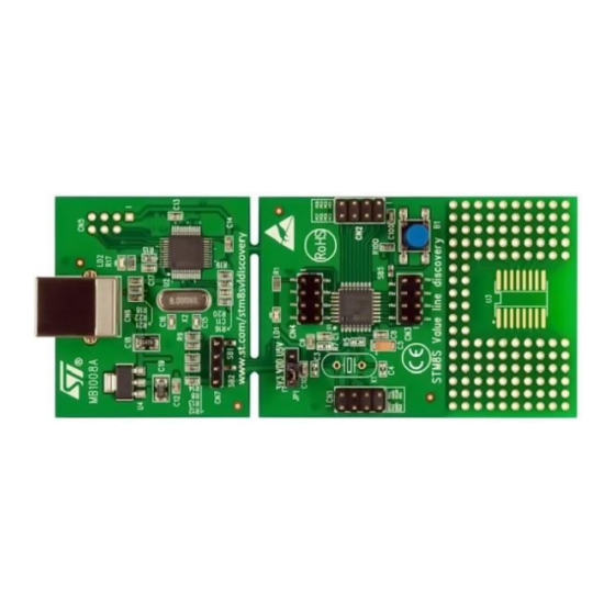
- Page 3 Overview of the Discovery Board For getting started with STM8s, STM has provided several STM8 Disco boards. There are also other third party boards too. However, I strongly recommend Disco boards for learning and experimental purposes. There are several reasons for this recommendation. One main reason is the fact that all Disco boards come with on-board detachable ST-Link programmers and they are extremely cheap.
- Page 4 There are also bulks of cheap Chinese minimum system STM8 dev boards hosting different STM8 chips. Overall the boards and the chips are so cheap that many simple cheap gadgets from China are based on STM8 MCUs. Some cheap STM8-based simple products are shown below: The first one is a cheap DIY LC meter LC-100A.
- Page 5 Hardware Tools The list of hardware tools needed is not very long. We will obviously need a STM8 board and I prefer a Discovery board over other boards since it comes with a built-in ST-Link programmer/debugger hardware. If you have some other board like the ones I already showed, you will need a ST-Link programmer.
- Page 6 It is yet better if you have either a logic analyser or oscilloscope. A good multimeter and a well- regulated DC power supply/source are must haves. You can also use a cell phone charging power bank as a power source since Disco boards have USB ports.
- Page 7 Cosmic used to be a paid tool just like your PC’s antivirus software but at the time of writing this article, the Cosmic team has made it absolutely free for STM8 family. However, to use it you will need to register and acquire a license key via email.
- Page 8 You need to register in order to download both software. For Cosmic you will also need to acquire a free license for it work. So just fill in some basic info about you. Firstly, we will need to install STVD. Installation procedure is simple and same as typical software installation.
- Page 9 After installation, you’ll prompted for licence. You must register your license unless you have already registered. If you have already registered, then you’ll be asked if to overwrite registration. You should skip reregistering. For the first run, you’ll get the following screen looking for a valid license. You must fill all the starred (*) points to complete the process of registration.
- Page 10 This was my emailed license. Once you get the license, you’ll need to show the software its location and complete the licensing process as shown below. Save the license file in a secured location. At the end of this process, we can enjoy the compiler without any limitations. I also recommend that you download Sublime Text (https://www.sublimetext.com/) or Notepad++ (https://notepad-plus-plus.org/) for viewing your code with ease.
- Page 11 STM8CubeMX was released in late February 2017. Yes, that’s the time when I was compiling all these STM8 stuffs together. Prior to that I was wondering about a software similar to STM32CubeMX but for STM8s. Back then, I could not find one and raw documentations were only helpers.
- Page 12 However, it does not specify the specifications of a given STM8 micro and that’s because it is a generalized literature for all STM8S and STM8AF micros. As we know even within a family of micros, one MCU differs from another in many aspects. Most commonly this variation comes in the form of memory capacities and I/O pin counts.
- Page 13 I wrote this article using SPL since it will be ridiculous to code STM8s using the old-fashioned way of configuring registers one-by-one manually. Thus, it is a mandatory download item. You should preserve and retain the downloaded SPL zip file fully intact. You may need it when things get messy. Now make two folders and name them “inc”...
- Page 14 Creating a New Code Project Assuming that STVD, STVP and Cosmic are properly installed, we will see how to create a new project. 1. Firstly, run STVD. 2. Select File >> New Workspace. 3. Select Create workspace and project.
- Page 15 4. Select workspace folder and workspace name. 5. Set project name and select toolchain STM8 Cosmic. You may need to set the path of your Cosmic compiler’s installation location. In my case, it is: C:\Program Files (x86)\COSMIC\FSE_Compilers\CXSTM8...
- Page 16 6. Type and select target chip part number. Last two or three digits and letters are enough for finding the correct micro. 7. Now add the source and header files from the previously mentioned SPL folder.
- Page 17 8. After file inclusions, the workspace tab changes as shown below. 9. Locate and open main.c file from the source tab, and then type #include "stm8s.h" at the top as shown below:...
- Page 18 10. You’ll have to edit the STM8S.h header file and uncomment the chip number you are going to use as shown below: 11. Compile the code once using the key combination CTRL+F7 or by pressing the compile button. If everything is okay, there should be no error or warning message. The reason for this blank compilation is to use the compiler’s powerful code assistant feature.
- Page 19 STM8 family. Thus, we have to debug our code in real-life with real hardware. It may sound difficult but actually it is not so. We can, however, use such software to make models of STM8 micros and make our PCBs. I don’t like simulations as they are not always accurate and real-world type.
- Page 20 Uploading Code Codes generated by Cosmic C compiler have s19 file extensions. It is similar to typical hex file format, containing user code as hex values. Well since we don’t need to modify finally generated output files, it doesn’t really matter in which format it is. All we will need is to upload them to our target MCUs. We can do it in two ways –...
- Page 21 Notice the mid tabs at the bottom of the hex values. From here we can see the hex values for program memory, data/EEPROM memory and configuration settings. The configuration setting bits are intended for setting some special hardware configurations or extending features of the target as well as setting memory readout protection.
- Page 22 We will get a new window as shown below: As the name of the new window suggests, it is a light-weight programmer interface but good enough for our purpose. Notice that there are many options and four tabs. Here again we need to select programmer, programming interface (SWIM) and erase/blank check options.
- Page 23 Next, we set configuration bits if needed from the tab as shown below: Finally, we are ready to upload code. Just hit the start button and wait for the process to finish. Every time a code is programmed, it is verified automatically.
- Page 24 General Purpose Input Output (GPIO) The very first “Hello World” project that we do with every new embedded device is a simple LED blinking program. Here we do the same. We will be basically testing both input and output function by making a variable flash rate blinking LED.
- Page 25 Shown below is the internal block diagram of GPIO pins: Because each I/O is independently configurable and have many options associated with it, its block looks complex at first sight. Check the various options every I/O possess:...
- Page 26 Shown below are the SPL functions associated with the GPIO module. Observe the code below. This is the power of the ST’s SPL. The code is written with no traditional register access. Everything here has a meaningful nomenclature, just like regular naming/words of the reference manual/comments.
- Page 27 Hardware Connection Code Example #include "STM8S.h" void main (void) bool i = 0; GPIO_DeInit(GPIOB); GPIO_DeInit(GPIOD); GPIO_Init(GPIOB, GPIO_PIN_7, GPIO_MODE_IN_FL_NO_IT); GPIO_Init(GPIOD, GPIO_PIN_0, GPIO_MODE_OUT_PP_LOW_FAST); for(;;) if(GPIO_ReadInputPin(GPIOB, GPIO_PIN_7) == FALSE) while(GPIO_ReadInputPin(GPIOB, GPIO_PIN_7) == FALSE);...
- Page 28 i ^= 1; switch(i) case 0: delay_ms(1000); break; case 1: delay_ms(200); break; GPIO_WriteReverse(GPIOD, GPIO_PIN_0); Explanation The following lines deinitialize the GPIOs we used. Every time you reconfigure or setup a hardware peripheral for the first time you must deinitialize it before using it. Though it is not mandatory, it will remove any chance of wrong/conflicting configurations.
- Page 29 case 1: delay_ms(200); break; GPIO_WriteReverse(GPIOD, GPIO_PIN_0); Demo Video link: https://www.youtube.com/watch?v=Rr1vpfoze4w...
- Page 30 Clock System (CLK) The internal network of STM8 clock system allows us to tune up operating speeds of peripherals and CPU according to our needs. Software delays and power consumption depend on how the clock system is set. In STM8 micros, there are three main clock sources – High Speed Internal Clock (HSI), High Speed External Clock (HSE) and Low Speed Internal Clock (LSI).
- Page 31 Hardware Connection...
- Page 32 Code Example The code example below demonstrates how to run the CPU at 2MHz clock using HSI and extract 500kHz clock output from CCO pin using CCO output selection. HSE is divided by 8, i.e. 16MHz divided by 8 equals 2MHz. This 2MHz is the master clock source and further divided four times to get 500kHz. Note CCO pin is only available in some pins.
- Page 33 CLK_CCOConfig(CLK_OUTPUT_CPU); CLK_CCOCmd(ENABLE); while(CLK_GetFlagStatus(CLK_FLAG_CCORDY) == FALSE); void GPIO_setup(void) GPIO_DeInit(LED_port); GPIO_Init(LED_port, LED_pin, GPIO_MODE_OUT_OD_HIZ_FAST); Explanation The full explanation of this code is given in the last segment of this article. The only thing I’ll describe here is this part: CLK_CCOConfig(CLK_OUTPUT_CPU); CLK_CCOCmd(ENABLE); while(CLK_GetFlagStatus(CLK_FLAG_CCORDY) == FALSE); These lines select the clock source that the CCO pin will output, enable the CCO module and wait for it to stabilize.
- Page 34 External Interrupt (EXTI) External interrupt is an additional feature of GPIOs in input mode. It makes a micro to respond instantly to changes done on it GPIO input pin(s) by an external events/triggers, skipping other tasks. External interrupts are useful in many scenarios. For instance, an emergency button. Consider the case of a treadmill.
- Page 35 Hardware Connection Code Example We will do the same variable flash rate LED blinking example as in the GPIO example but this time with the DISCO board’s button in external interrupt mode. The code here needs special attention as now we will see how interrupts are configured and coded.
- Page 36 Now check the interrupt vector table of STM8S003 below: You’ll find this table not in the reference manual but in the device’s datasheet. This table varies with devices and so be sure of correct datasheet. The DISCO board’s button is connected to PB7 and so clearly, we will need IRQ4, i.e.
- Page 37 main.c #include "stm8s.h" bool state = FALSE; void GPIO_setup(void); void EXTI_setup(void); void clock_setup(void); void main(void) GPIO_setup(); EXTI_setup(); clock_setup(); GPIO_WriteReverse(GPIOD, GPIO_PIN_0); if(state == TRUE) delay_ms(100); else delay_ms(1000); }while (TRUE); void GPIO_setup(void) GPIO_DeInit(GPIOB); GPIO_Init(GPIOB, GPIO_PIN_7, GPIO_MODE_IN_PU_IT); GPIO_DeInit(GPIOD); GPIO_Init(GPIOD, GPIO_PIN_0, GPIO_MODE_OUT_PP_LOW_FAST); void EXTI_setup(void) ITC_DeInit();...
- Page 38 CLK_PeripheralClockConfig(CLK_PERIPHERAL_ADC, DISABLE); CLK_PeripheralClockConfig(CLK_PERIPHERAL_AWU, DISABLE); CLK_PeripheralClockConfig(CLK_PERIPHERAL_UART1, DISABLE); CLK_PeripheralClockConfig(CLK_PERIPHERAL_TIMER1, DISABLE); CLK_PeripheralClockConfig(CLK_PERIPHERAL_TIMER2, DISABLE); CLK_PeripheralClockConfig(CLK_PERIPHERAL_TIMER4, DISABLE); stm8_interrupt_vector.c BASIC INTERRUPT VECTOR TABLE FOR STM8 devices Copyright (c) 2007 STMicroelectronics #include "stm8s_it.h" typedef void @far (*interrupt_handler_t)(void); struct interrupt_vector { unsigned char interrupt_instruction; interrupt_handler_t interrupt_handler; //@far @interrupt void NonHandledInterrupt (void)
- Page 39 {0x82, NonHandledInterrupt}, /* irq18 */ {0x82, NonHandledInterrupt}, /* irq19 */ {0x82, NonHandledInterrupt}, /* irq20 */ {0x82, NonHandledInterrupt}, /* irq21 */ {0x82, NonHandledInterrupt}, /* irq22 */ {0x82, NonHandledInterrupt}, /* irq23 */ {0x82, NonHandledInterrupt}, /* irq24 */ {0x82, NonHandledInterrupt}, /* irq25 */ {0x82, NonHandledInterrupt}, /* irq26 */ {0x82, NonHandledInterrupt}, /* irq27 */ {0x82, NonHandledInterrupt}, /* irq28 */...
- Page 40 Explanation Most part of the code is same as previous codes and so I won’t be going through them again. However, there’s something new: void EXTI_setup(void) ITC_DeInit(); ITC_SetSoftwarePriority(ITC_IRQ_PORTB, ITC_PRIORITYLEVEL_0); EXTI_DeInit(); EXTI_SetExtIntSensitivity(EXTI_PORT_GPIOB, EXTI_SENSITIVITY_FALL_ONLY); EXTI_SetTLISensitivity(EXTI_TLISENSITIVITY_FALL_ONLY); enableInterrupts(); This function is where we are setting up the external interrupt. The first two lines deinitiate the interrupt controller and set priority while initiating it.
- Page 41 LSI to generate 1kHz, 2kHz and 4kHz square wave outputs that can be directly feed to a small piezo tweeter (not buzzer). In most STM8 micros, the beeper module’s I/O pin (PD4) is not accessible unless alternate function configuration bit is altered during code upload. However, there are few exceptional chips like the STM8S003 in which we don’t need to change any configuration bit at all.
- Page 42 Code Example #include "STM8S.h" void clock_setup(void); void GPIO_setup(void); void beeper_setup(void); void main(void) clock_setup(); GPIO_setup(); beeper_setup(); while(TRUE) GPIO_WriteLow(GPIOD, GPIO_PIN_0); BEEP_Cmd(ENABLE); delay_ms(200); GPIO_WriteHigh(GPIOD, GPIO_PIN_0); BEEP_Cmd(DISABLE); delay_ms(200); void clock_setup(void) CLK_DeInit(); CLK_HSECmd(DISABLE); CLK_LSICmd(ENABLE); while(CLK_GetFlagStatus(CLK_FLAG_LSIRDY) == FALSE); CLK_HSICmd(ENABLE); while(CLK_GetFlagStatus(CLK_FLAG_HSIRDY) == FALSE); CLK_ClockSwitchCmd(ENABLE); CLK_HSIPrescalerConfig(CLK_PRESCALER_HSIDIV1); CLK_SYSCLKConfig(CLK_PRESCALER_CPUDIV1); CLK_ClockSwitchConfig(CLK_SWITCHMODE_AUTO, CLK_SOURCE_HSI, DISABLE, CLK_CURRENTCLOCKSTATE_ENABLE);...
- Page 43 BEEP_DeInit(); BEEP_LSICalibrationConfig(128000); BEEP_Init(BEEP_FREQUENCY_2KHZ); Explanation As stated earlier beeper module is dependent on the AWU module and so we need to enable this module’s peripheral clock: CLK_PeripheralClockConfig(CLK_PERIPHERAL_AWU, ENABLE); We need to set the beeper port pin as an output pin: GPIO_Init(GPIOD, GPIO_PIN_4, GPIO_MODE_OUT_PP_HIGH_FAST); Configuring the beeper is straight.
- Page 44 To interface a LCD with a STM8 micro, we need LCD library. The STM8 SPL does not have a library for such displays and we need to code it on our own. Interfacing a LCDs are not difficult tasks as no special hardware is required to drive LCDs other than GPIOs.
- Page 45 Code Example lcd.h #include "stm8s.h" #define LCD_PORT GPIOD #define LCD_RS GPIO_PIN_2 #define LCD_EN GPIO_PIN_3 #define LCD_DB4 GPIO_PIN_4 #define LCD_DB5 GPIO_PIN_5 #define LCD_DB6 GPIO_PIN_6 #define LCD_DB7 GPIO_PIN_7 #define clear_display 0x01 #define goto_home 0x02 #define cursor_direction_inc (0x04 | 0x02) #define cursor_direction_dec (0x04 | 0x00) #define display_shift (0x04 | 0x01) #define display_no_shift...
- Page 46 lcd.c #include "lcd.h" void LCD_GPIO_init(void) GPIO_Init(LCD_PORT, LCD_RS, GPIO_MODE_OUT_PP_HIGH_FAST); GPIO_Init(LCD_PORT, LCD_EN, GPIO_MODE_OUT_PP_HIGH_FAST); GPIO_Init(LCD_PORT, LCD_DB4, GPIO_MODE_OUT_PP_HIGH_FAST); GPIO_Init(LCD_PORT, LCD_DB5, GPIO_MODE_OUT_PP_HIGH_FAST); GPIO_Init(LCD_PORT, LCD_DB6, GPIO_MODE_OUT_PP_HIGH_FAST); GPIO_Init(LCD_PORT, LCD_DB7, GPIO_MODE_OUT_PP_HIGH_FAST); delay_ms(10); void LCD_init(void) LCD_GPIO_init(); toggle_EN_pin(); GPIO_WriteLow(LCD_PORT, LCD_RS); GPIO_WriteLow(LCD_PORT, LCD_DB7); GPIO_WriteLow(LCD_PORT, LCD_DB6); GPIO_WriteHigh(LCD_PORT, LCD_DB5); GPIO_WriteHigh(LCD_PORT, LCD_DB4); toggle_EN_pin(); GPIO_WriteLow(LCD_PORT, LCD_DB7); GPIO_WriteLow(LCD_PORT, LCD_DB6);...
- Page 47 break; LCD_4bit_send(value); void LCD_4bit_send(unsigned char lcd_data) toggle_io(lcd_data, 7, LCD_DB7); toggle_io(lcd_data, 6, LCD_DB6); toggle_io(lcd_data, 5, LCD_DB5); toggle_io(lcd_data, 4, LCD_DB4); toggle_EN_pin(); toggle_io(lcd_data, 3, LCD_DB7); toggle_io(lcd_data, 2, LCD_DB6); toggle_io(lcd_data, 1, LCD_DB5); toggle_io(lcd_data, 0, LCD_DB4); toggle_EN_pin(); void LCD_putstr(char *lcd_string) LCD_send(*lcd_string++, DAT); }while(*lcd_string != '\0'); void LCD_putchar(char char_data) LCD_send(char_data, DAT);...
- Page 48 bool temp = FALSE; temp = (0x01 & (lcd_data >> bit_pos)); switch(temp) case TRUE: GPIO_WriteHigh(LCD_PORT, pin_num); break; default: GPIO_WriteLow(LCD_PORT, pin_num); break; main.c #include "STM8S.h" #include "lcd.h" void clock_setup(void); void GPIO_setup(void); void main(void) const char txt1[] = {"MICROARENA"}; const char txt2[] = {"SShahryiar"}; const char txt3[] = {"STM8S003K"};...
- Page 49 delay_ms(90); while (TRUE); void clock_setup(void) CLK_DeInit(); CLK_HSECmd(DISABLE); CLK_LSICmd(DISABLE); CLK_HSICmd(ENABLE); while(CLK_GetFlagStatus(CLK_FLAG_HSIRDY) == FALSE); CLK_ClockSwitchCmd(ENABLE); CLK_HSIPrescalerConfig(CLK_PRESCALER_HSIDIV8); CLK_SYSCLKConfig(CLK_PRESCALER_CPUDIV1); CLK_ClockSwitchConfig(CLK_SWITCHMODE_AUTO, CLK_SOURCE_HSI, DISABLE, CLK_CURRENTCLOCKSTATE_ENABLE); CLK_PeripheralClockConfig(CLK_PERIPHERAL_SPI, DISABLE); CLK_PeripheralClockConfig(CLK_PERIPHERAL_I2C, DISABLE); CLK_PeripheralClockConfig(CLK_PERIPHERAL_ADC, DISABLE); CLK_PeripheralClockConfig(CLK_PERIPHERAL_AWU, DISABLE); CLK_PeripheralClockConfig(CLK_PERIPHERAL_UART1, DISABLE); CLK_PeripheralClockConfig(CLK_PERIPHERAL_TIMER1, DISABLE); CLK_PeripheralClockConfig(CLK_PERIPHERAL_TIMER2, DISABLE); CLK_PeripheralClockConfig(CLK_PERIPHERAL_TIMER4, DISABLE); void GPIO_setup(void) GPIO_DeInit(LCD_PORT); Explanation There’s little to explain this code as it involves GPIOs only. The codes for the LCD are coded using all available info on its datasheet, just initialization and working principle.
- Page 50 Demo Video link: https://www.youtube.com/watch?v=TJg2Tuu4QaQ...
- Page 51 ADC block. Other STM8 micros have more ADC channels and ADC blocks. The ADC of STM8 micros is just as same as the ADCs of other micros. There are a few additional features. Shown below is the block diagram of the STM8’s ADC peripheral: A few things must be noted before using the ADC.
- Page 52 Hardware Connection Code Example #include "STM8S.h" void clock_setup(void); void GPIO_setup(void); void ADC1_setup(void); void lcd_print(unsigned char x_pos, unsigned char y_pos, unsigned int value); void main() unsigned int A0 = 0x0000; clock_setup(); GPIO_setup(); ADC1_setup();...
- Page 53 LCD_init(); LCD_clear_home(); LCD_goto(0, 0); LCD_putstr("STM8 ADC"); LCD_goto(0, 1); LCD_putstr("A0"); while(TRUE) ADC1_StartConversion(); while(ADC1_GetFlagStatus(ADC1_FLAG_EOC) == FALSE); A0 = ADC1_GetConversionValue(); ADC1_ClearFlag(ADC1_FLAG_EOC); lcd_print(4, 1, A0); delay_ms(90); void clock_setup(void) CLK_DeInit(); CLK_HSECmd(DISABLE); CLK_LSICmd(DISABLE); CLK_HSICmd(ENABLE); while(CLK_GetFlagStatus(CLK_FLAG_HSIRDY) == FALSE); CLK_ClockSwitchCmd(ENABLE); CLK_HSIPrescalerConfig(CLK_PRESCALER_HSIDIV2); CLK_SYSCLKConfig(CLK_PRESCALER_CPUDIV4); CLK_ClockSwitchConfig(CLK_SWITCHMODE_AUTO, CLK_SOURCE_HSI, DISABLE, CLK_CURRENTCLOCKSTATE_ENABLE); CLK_PeripheralClockConfig(CLK_PERIPHERAL_SPI, DISABLE);...
- Page 54 ADC1_PRESSEL_FCPU_D18, ADC1_EXTTRIG_GPIO, DISABLE, ADC1_ALIGN_RIGHT, ADC1_SCHMITTTRIG_CHANNEL0, DISABLE); ADC1_Cmd(ENABLE); void lcd_print(unsigned char x_pos, unsigned char y_pos, unsigned int value) char chr = 0x00; chr = ((value / 1000) + 0x30); LCD_goto(x_pos, y_pos); LCD_putchar(chr); chr = (((value / 100) % 10) + 0x30); LCD_goto((x_pos + 1), y_pos);...
- Page 55 The second line of the above function states that we are going to use ADC channel 0 (PB0) with no Schmitt trigger. We are also not going to use external triggers from timer/GPIO modules. Since the master clock is running at 8MHz, the ADC prescaler divides the master/peripheral clock to get a sampling frequency of 444kHz.
- Page 56 Analog Watchdog (AWD) The AWD is one additional feature that most microcontrollers in the market do not have. AWD is more like a comparator but with the exception that we can set both the upper and lower limits of this comparator as per our requirement unlike fixed levels in other micros.
- Page 57 Hardware Connection Code Example #include "STM8S.h" void clock_setup(void); void GPIO_setup(void); void ADC1_setup(void); void lcd_print(unsigned char x_pos, unsigned char y_pos, unsigned int value); void main() unsigned int a1 = 0x0000; clock_setup(); GPIO_setup(); ADC1_setup(); LCD_init(); LCD_clear_home();...
- Page 58 LCD_goto(0, 0); LCD_putstr("STM8 AWD"); LCD_goto(0, 1); LCD_putstr("A1"); while (TRUE) ADC1_ClearFlag(ADC1_FLAG_EOC); ADC1_StartConversion(); while(ADC1_GetFlagStatus(ADC1_FLAG_EOC) == 0); a1 = ADC1_GetConversionValue(); lcd_print(4, 1, a1); if(ADC1_GetFlagStatus(ADC1_FLAG_AWD)) GPIO_WriteReverse(GPIOD, GPIO_PIN_0); ADC1_ClearFlag(ADC1_FLAG_AWD); else GPIO_WriteHigh(GPIOD, GPIO_PIN_0); delay_ms(90); void clock_setup(void) CLK_DeInit(); CLK_HSECmd(DISABLE); CLK_LSICmd(DISABLE); CLK_HSICmd(ENABLE); while(CLK_GetFlagStatus(CLK_FLAG_HSIRDY) == FALSE); CLK_ClockSwitchCmd(ENABLE); CLK_HSIPrescalerConfig(CLK_PRESCALER_HSIDIV2); CLK_SYSCLKConfig(CLK_PRESCALER_CPUDIV4);...
- Page 59 void ADC1_setup(void) ADC1_DeInit(); ADC1_Init(ADC1_CONVERSIONMODE_SINGLE, ADC1_CHANNEL_1, ADC1_PRESSEL_FCPU_D10, ADC1_EXTTRIG_GPIO, DISABLE, ADC1_ALIGN_RIGHT, ADC1_SCHMITTTRIG_CHANNEL1, DISABLE); ADC1_AWDChannelConfig(ADC1_CHANNEL_1, ENABLE); ADC1_SetHighThreshold(600); ADC1_SetLowThreshold(200); ADC1_Cmd(ENABLE); void lcd_print(unsigned char x_pos, unsigned char y_pos, unsigned int value) char chr = 0x00; chr = ((value / 1000) + 0x30); LCD_goto(x_pos, y_pos); LCD_putchar(chr); chr = (((value / 100) % 10) + 0x30);...
- Page 60 In the main function, we are simply polling AWD flag. If an AWD (beyond boundary zone) event on PB1 pin occurs the LED on PD0 starts flashing. If PB1 senses voltage between 200 and 600 ADC counts, the LED is turned off, indicating guarded zone. if(ADC1_GetFlagStatus(ADC1_FLAG_AWD)) GPIO_WriteReverse(GPIOD, GPIO_PIN_0);...
- Page 61 Demo Video link: https://www.youtube.com/watch?v=bvVNuVpeFPk...
- Page 62 Independent Watchdog (IWDG) The IWDG is just the ordinary watchdog timer we usually find in any modern micro. The purpose of this timer is to recover a micro from an unanticipated event that may result in unresponsive or erratic behaviour. As the name suggests, this timer does not share anything with any other internal hardware peripheral and is clocked by LSI (128kHz) only.
- Page 63 Typical values of timeout are as shown below: Hardware Connection...
- Page 64 Code Example #include "STM8S.h" void clock_setup(void); void GPIO_setup(void); void IWDG_setup(void); void main(void) unsigned int t = 0; clock_setup(); GPIO_setup(); GPIO_WriteLow(GPIOD, GPIO_PIN_0); for(t = 0; t < 60000; t++); IWDG_setup(); while(TRUE) GPIO_WriteReverse(GPIOD, GPIO_PIN_0); for(t = 0; t < 1000; t++) if(GPIO_ReadInputPin(GPIOB, GPIO_PIN_7) == FALSE) IWDG_WriteAccessCmd(IWDG_WriteAccess_Enable);...
- Page 65 void GPIO_setup(void) GPIO_DeInit(GPIOB); GPIO_DeInit(GPIOD); GPIO_Init(GPIOB, GPIO_PIN_7, GPIO_MODE_IN_PU_NO_IT); GPIO_Init(GPIOD, GPIO_PIN_0, GPIO_MODE_OUT_PP_LOW_FAST); void IWDG_setup(void) IWDG_Enable(); IWDG_WriteAccessCmd(IWDG_WriteAccess_Enable); IWDG_SetPrescaler(IWDG_Prescaler_128); IWDG_SetReload(0x99); IWDG_WriteAccessCmd(IWDG_WriteAccess_Disable); Explanation In this example, we need not to look at peripheral and CPU clock as IWDG is not dependent on them. Still we can see that the CPU is running at 500kHz speed while the peripherals at 2MHz speed. CLK_HSIPrescalerConfig(CLK_PRESCALER_HSIDIV8);...
- Page 66 Note it is possible to calibrate LSI. It is however rarely needed. Demo Video link: https://www.youtube.com/watch?v=05XKoy0ieHo...
- Page 67 Window Watchdog (WWDG) The WWDG is a bit more advanced watchdog timer. Unlike the IWDG, it will trigger a reset condition if its counter is reloaded earlier or later than a predefined time window. This kind of timer is usually found in high-end microcontrollers like ARMs, ATXMegas and recently released micros.
- Page 68 Hardware Connection Code Example The code example here demonstrates WWDG action. Simply Disco board’s user LED and button are used. When the code starts executing, the LED starts blinking slowly, indicating the start of the code. When the code executes the main loop, the LED blinks rapidly to indicate main loop execution. If the button is pressed randomly the micro is reset because the counter is refreshed before the allowed time.
- Page 69 GPIO_WriteReverse(GPIOD, GPIO_PIN_0); delay_ms(40); WWDG_setup(); while(TRUE) if((GPIO_ReadInputPin(GPIOB, GPIO_PIN_7) == FALSE) || ((WWDG_GetCounter() > 0x60) && (WWDG_GetCounter() < 0x7F))) WWDG_SetCounter(0x7F); GPIO_WriteReverse(GPIOD, GPIO_PIN_0); delay_ms(20); void clock_setup(void) CLK_DeInit(); CLK_HSECmd(DISABLE); CLK_LSICmd(DISABLE); CLK_HSICmd(ENABLE); while(CLK_GetFlagStatus(CLK_FLAG_HSIRDY) == FALSE); CLK_ClockSwitchCmd(ENABLE); CLK_HSIPrescalerConfig(CLK_PRESCALER_HSIDIV8); CLK_SYSCLKConfig(CLK_PRESCALER_CPUDIV64); CLK_ClockSwitchConfig(CLK_SWITCHMODE_AUTO, CLK_SOURCE_HSI, DISABLE, CLK_CURRENTCLOCKSTATE_ENABLE); CLK_PeripheralClockConfig(CLK_PERIPHERAL_I2C, DISABLE); CLK_PeripheralClockConfig(CLK_PERIPHERAL_SPI, DISABLE); CLK_PeripheralClockConfig(CLK_PERIPHERAL_ADC, DISABLE);...
- Page 70 Explanation There’s no way to enable watchdogs manually in software as they are always enabled. However, there are configuration bits to select if the IWDG and the WWDG are enabled in software or hardware. They only come in effect when configured. This is cool. For WWDG, we just need to set the value of the down counter and the window register value only.
- Page 71 Here’s the summary of all timers of STM8 micros: Unlike the timers of other micros, STM8 timers have the more functionality that are otherwise only available in some special micros only. Timer cover a significant part of the reference manual. They are so elaborate that it is not possible to describe all of them in just one post.
- Page 72 Real-Time Operating System (RTOS) and many other tasks. The time base unit for all timers of STM8 is all same. There are a few differences. For example, Timer 1 (TIM1) has a repetition counter. It is like a counter within another counter. Other timers lack this part.
- Page 73 Hardware Connection Code Example In this example, Disco board’s user LED is turned-on and off without using any software delay. TIM2 is used to create time delay as such that the code is not stuck in a time-wasting loop. #include "STM8S.h" void clock_setup(void);...
- Page 74 GPIO_WriteHigh(GPIOD, GPIO_PIN_0); else GPIO_WriteLow(GPIOD, GPIO_PIN_0); void clock_setup(void) CLK_DeInit(); CLK_HSECmd(DISABLE); CLK_LSICmd(DISABLE); CLK_HSICmd(ENABLE); while(CLK_GetFlagStatus(CLK_FLAG_HSIRDY) == FALSE); CLK_ClockSwitchCmd(ENABLE); CLK_HSIPrescalerConfig(CLK_PRESCALER_HSIDIV8); CLK_SYSCLKConfig(CLK_PRESCALER_CPUDIV1); CLK_ClockSwitchConfig(CLK_SWITCHMODE_AUTO, CLK_SOURCE_HSI, DISABLE, CLK_CURRENTCLOCKSTATE_ENABLE); CLK_PeripheralClockConfig(CLK_PERIPHERAL_SPI, DISABLE); CLK_PeripheralClockConfig(CLK_PERIPHERAL_I2C, DISABLE); CLK_PeripheralClockConfig(CLK_PERIPHERAL_ADC, DISABLE); CLK_PeripheralClockConfig(CLK_PERIPHERAL_AWU, DISABLE); CLK_PeripheralClockConfig(CLK_PERIPHERAL_UART1, DISABLE); CLK_PeripheralClockConfig(CLK_PERIPHERAL_TIMER1, DISABLE); CLK_PeripheralClockConfig(CLK_PERIPHERAL_TIMER2, ENABLE); CLK_PeripheralClockConfig(CLK_PERIPHERAL_TIMER4, DISABLE); void GPIO_setup(void) GPIO_DeInit(GPIOD); GPIO_Init(GPIOD, GPIO_PIN_0, GPIO_MODE_OUT_OD_HIZ_SLOW);...
- Page 75 As explained earlier, to get 2 second timer reload interval we need to prescale the timer by 2048 and load its counter with 1952. This is what should be the setup for TIM2: void TIM2_setup(void) TIM2_DeInit(); TIM2_TimeBaseInit(TIM2_PRESCALER_2048, 1952); TIM2_Cmd(ENABLE); Our goal is to keep the LED on for 1 second and off for 1 second. It takes 1952 TIM2 counts for 2 second interval and so one second passes when this count is 976.
- Page 76 Timer Interrupt (TIM4) In this example uses the same concepts of the previous example but it is based on timer interrupt – TIM4 interrupt. Timer interrupts are very important interrupts apart from other interrupts in a micro. To me they are highly valuable and useful. This example demonstrates how to scan and project information on multiple seven segment displays with timer interrupt while the main loop can process the information to be displayed.
- Page 77 void GPIO_setup(void); void clock_setup(void); void TIM4_setup(void); void main(void) GPIO_setup(); clock_setup(); TIM4_setup(); while (TRUE) value++; delay_ms(999); void GPIO_setup(void) GPIO_DeInit(GPIOC); GPIO_Init(GPIOC, ((GPIO_Pin_TypeDef)(GPIO_PIN_4 | GPIO_PIN_5 | GPIO_PIN_6 | GPIO_PIN_7)), GPIO_MODE_OUT_PP_HIGH_FAST); GPIO_DeInit(GPIOD); GPIO_Init(GPIOD, GPIO_PIN_ALL, GPIO_MODE_OUT_PP_HIGH_FAST); void clock_setup(void) CLK_DeInit(); CLK_HSECmd(DISABLE); CLK_LSICmd(DISABLE); CLK_HSICmd(ENABLE); while(CLK_GetFlagStatus(CLK_FLAG_HSIRDY) == FALSE); CLK_ClockSwitchCmd(ENABLE);...
- Page 78 stm8s_it.h (top part only) #ifndef __STM8S_IT_H #define __STM8S_IT_H @far @interrupt void TIM4_UPD_IRQHandler(void); /* Includes ------------------------------------------------------------------*/ #include "stm8s.h" stm8s_it.c (top part only) #include "stm8s.h" #include "stm8s_it.h" extern unsigned int value; extern unsigned char n; extern unsigned char seg; extern const unsigned char num[10]; void TIM4_UPD_IRQHandler(void) switch(seg) case 1:...
- Page 79 seg = 1; TIM4_ClearFlag(TIM4_FLAG_UPDATE); stm8_interrupt_vector.c #include "stm8s_it.h" typedef void @far (*interrupt_handler_t)(void); struct interrupt_vector { unsigned char interrupt_instruction; interrupt_handler_t interrupt_handler; //@far @interrupt void NonHandledInterrupt (void) /* in order to detect unexpected events during development, it is recommended to set a breakpoint on the following instruction //return;...
- Page 80 Explanation Both the peripheral and CPU clocks are running at 2MHz. CLK_HSIPrescalerConfig(CLK_PRESCALER_HSIDIV8); CLK_SYSCLKConfig(CLK_PRESCALER_CPUDIV1); ..…. CLK_PeripheralClockConfig(CLK_PERIPHERAL_TIMER4, ENABLE); TIM4 is a basic timer and so it is better to use it for such tasks. We initialize it by setting its prescaler to 32 and loading its counter with 128.
- Page 81 n = ((value / 10) % 10); GPIO_Write(GPIOD, num[n]); GPIO_Write(GPIOC, 0xB0); break; case 4: n = (value % 10); GPIO_Write(GPIOD, num[n]); GPIO_Write(GPIOC, 0x70); break; seg++; if(seg > 4) seg = 1; TIM4_ClearFlag(TIM4_FLAG_UPDATE); Demo Video link: https://youtu.be/Sa20Hf2N4gE...
- Page 82 Please note that in more advanced STM8 micros, timer I/Os are dependent on alternate function configuration bits. Check those bits before uploading codes. In some STM8 micros, the I/Os are also remappable, meaning that the I/Os can be swapped in different GPIOs. Take the help of STM8CubeMx if needed.
- Page 83 Code Example This is a pretty simple example. Here all three channels of TIM2 are used to smoothly fade and glow three LEDs connected to the timer channels. #include "STM8S.h" void clock_setup(void); void GPIO_setup(void); void TIM2_setup(void); void main(void) signed int pwm_duty = 0x0000; clock_setup();...
- Page 84 void GPIO_setup(void) GPIO_DeInit(GPIOA); GPIO_Init(GPIOA, GPIO_PIN_3, GPIO_MODE_OUT_PP_HIGH_FAST); GPIO_DeInit(GPIOD); GPIO_Init(GPIOD, ((GPIO_Pin_TypeDef)GPIO_PIN_3 | GPIO_PIN_4), GPIO_MODE_OUT_PP_HIGH_FAST); void TIM2_setup(void) TIM2_DeInit(); TIM2_TimeBaseInit(TIM2_PRESCALER_32, 1000); TIM2_OC1Init(TIM2_OCMODE_PWM1, TIM2_OUTPUTSTATE_ENABLE, 1000, TIM2_OCPOLARITY_HIGH); TIM2_OC2Init(TIM2_OCMODE_PWM1, TIM2_OUTPUTSTATE_ENABLE, 1000, TIM2_OCPOLARITY_LOW); TIM2_OC3Init(TIM2_OCMODE_PWM1, TIM2_OUTPUTSTATE_ENABLE, 1000, TIM2_OCPOLARITY_HIGH); TIM2_Cmd(ENABLE); Explanation Again, the CPU and the peripheral clock is set at 2MHz. CLK_HSIPrescalerConfig(CLK_PRESCALER_HSIDIV8);...
- Page 85 // where X represents channel ID (1, 2 or 3) Note that in STM8 micros, there is a trade-off between duty cycle and PWM frequency. If the PWM resolution, i.e. duty cycle is big then PWM frequency is small and vice-versa. This is true for all timers.
- Page 86 Advanced Pulse Width Modulation (TIM1 PWM) Timer 1 (TIM1) is an advance timer and so the PWMs generated by it have several additional features that are not available with other timers. For example, it is possible to generate complimentary PWMs with TIM1.
- Page 87 Code Example #include "STM8S.h" void clock_setup(void); void GPIO_setup(void); void TIM1_setup(void); void main(void) signed int i = 0; clock_setup(); GPIO_setup(); TIM1_setup(); while(TRUE) for(i = 0; i < 1000; i += 1) TIM1_SetCompare1(i); delay_ms(1); for(i = 1000; i > 0; i -= 1) TIM1_SetCompare1(i);...
- Page 88 TIM1 has additional repetition counter. • Except the basic timers all timers in STM8 are 16-bit timer. If you open the header file for TIM1, you’ll see many functions. Many of these functions are not available with other timers, expressing the power of an advance timer.
- Page 89 Likewise, there are some additional info we must feed when configuring the OC channels. We need to set info about complementary channels even if we don’t need them. We can additionally set the default idle states of PWMs apart from polarities. void TIM1_setup(void) TIM1_DeInit();...
- Page 90 Demo Video link: https://youtu.be/uclCXH1ZPWU...
- Page 91 PWM measurement less complex and resource-friendly too. STM8 timers have several capture channels just like output compare channels (PWM). The number of input capture channels is same as the number of PWM channels. Except basic timers all timers have input capture option.
- Page 92 Code Example In this demo, TIM2 is configured to generate PWM on its CH1 output. TIM1 is configured to capture every rising edge of incoming waveform at its input capture channel CH1. When a capture event occurs, the current time count of TIM1 is saved. By deducting the recent capture count from the previous capture count, we can measure time period of the incoming PWM signal and hence its frequency.
- Page 93 CLK_SYSCLKConfig(CLK_PRESCALER_CPUDIV2); CLK_ClockSwitchConfig(CLK_SWITCHMODE_AUTO, CLK_SOURCE_HSI, DISABLE, CLK_CURRENTCLOCKSTATE_ENABLE); CLK_PeripheralClockConfig(CLK_PERIPHERAL_SPI, DISABLE); CLK_PeripheralClockConfig(CLK_PERIPHERAL_I2C, DISABLE); CLK_PeripheralClockConfig(CLK_PERIPHERAL_ADC, DISABLE); CLK_PeripheralClockConfig(CLK_PERIPHERAL_AWU, DISABLE); CLK_PeripheralClockConfig(CLK_PERIPHERAL_UART1, DISABLE); CLK_PeripheralClockConfig(CLK_PERIPHERAL_TIMER1, ENABLE); CLK_PeripheralClockConfig(CLK_PERIPHERAL_TIMER2, ENABLE); CLK_PeripheralClockConfig(CLK_PERIPHERAL_TIMER4, DISABLE); void GPIO_setup(void) GPIO_DeInit(GPIOC); GPIO_Init(GPIOC, GPIO_PIN_1, GPIO_MODE_IN_FL_NO_IT); GPIO_DeInit(GPIOD); GPIO_Init(GPIOD, GPIO_PIN_4, GPIO_MODE_OUT_PP_HIGH_FAST); void TIM1_setup(void) TIM1_DeInit(); TIM1_TimeBaseInit(2000, TIM1_COUNTERMODE_UP, 55535, 1); TIM1_ICInit(TIM1_CHANNEL_1, TIM1_ICPOLARITY_RISING, TIM1_ICSELECTION_DIRECTTI, 1, 1); TIM1_ITConfig(TIM1_IT_UPDATE, ENABLE);...
- Page 94 stm8_interrupt_vector.c (Interrupt vector address part only) …. {0x82, (interrupt_handler_t)TIM1_UPD_IRQHandler}, /* irq11 */ {0x82, (interrupt_handler_t)TIM1_CH1_CCP_IRQHandler}, /* irq12 */ …. stm8s_it.h (Top part only) #ifndef __STM8S_IT_H #define __STM8S_IT_H @far @interrupt void TIM1_UPD_IRQHandler(void); @far @interrupt void TIM1_CH1_CCP_IRQHandler(void); /* Includes ------------------------------------------------------------------*/ #include "stm8s.h" …. stm8s_it.c (Top part only) #include "stm8s.h"...
- Page 95 Explanation The clocks and peripherals are set first. We are using 2MHz peripheral clock and the CPU is running at 0.5MHz. CLK_HSIPrescalerConfig(CLK_PRESCALER_HSIDIV8); CLK_SYSCLKConfig(CLK_PRESCALER_CPUDIV2); …. …. CLK_PeripheralClockConfig(CLK_PERIPHERAL_TIMER1, ENABLE); CLK_PeripheralClockConfig(CLK_PERIPHERAL_TIMER2, ENABLE); GPIOs must be set too. Since TIM2 is to output PWM, its CH1 must be set output. Likewise, TIM1’s CH1 GPIO must be set as an input.
- Page 96 We have to specify the interrupt subroutine (ISR) prototype functions in the stm8s_it.h file. These functions are the places where the code will jump when respective interrupt occurs: @far @interrupt void TIM1_UPD_IRQHandler(void); @far @interrupt void TIM1_CH1_CCP_IRQHandler(void); The ISR functions are coded in the stm8s_it.c file: void TIM1_UPD_IRQHandler(void) overflow_count++;...
- Page 97 Demo Video link: https://youtu.be/bzLUDwuFQTw...
- Page 98 Wireless serial communication IrDA 115.2kbps <1m 2 (Point-to-Point) using infrared medium In STM8 microcontrollers, LIN, IrDA, RS-485 and UART all share the UART hardware peripheral. For other communications, there are dedicated separate hardware. We will now be exploring the basic ones here.
- Page 99 To learn more about UART visit the following link: https://learn.mikroe.com/uart-serial-communication/ The UARTs of STM8 micros are so robust and packed with so many features that it is quite impossible to explain them all in this one article. Here we will explore the basic serial communication only. LIN...
- Page 100 Hardware Connection Code Example #include "STM8S.h" void clock_setup(void); void GPIO_setup(void); void UART1_setup(void); void main(void) unsigned char i = 0; char ch = 0; clock_setup();...
- Page 101 GPIO_setup(); UART1_setup(); LCD_init(); LCD_clear_home(); LCD_goto(0, 0); LCD_putstr("TX:"); LCD_goto(0, 1); LCD_putstr("RX:"); while(TRUE) if(UART1_GetFlagStatus(UART1_FLAG_RXNE) == TRUE) ch = UART1_ReceiveData8(); LCD_goto(7, 1); LCD_putchar(ch); UART1_ClearFlag(UART1_FLAG_RXNE); UART1_SendData8(i + 0x30); if(UART1_GetFlagStatus(UART1_FLAG_TXE) == FALSE) LCD_goto(7, 0); LCD_putchar(i + 0x30); i++; void clock_setup(void) CLK_DeInit(); CLK_HSECmd(DISABLE); CLK_LSICmd(DISABLE); CLK_HSICmd(ENABLE); while(CLK_GetFlagStatus(CLK_FLAG_HSIRDY) == FALSE); CLK_ClockSwitchCmd(ENABLE);...
- Page 102 UART1_DeInit(); UART1_Init(9600, UART1_WORDLENGTH_8D, UART1_STOPBITS_1, UART1_PARITY_NO, UART1_SYNCMODE_CLOCK_DISABLE, UART1_MODE_TXRX_ENABLE); UART1_Cmd(ENABLE); Explanation The peripheral and CPU clocks are set at 2MHz: CLK_HSIPrescalerConfig(CLK_PRESCALER_HSIDIV8); CLK_SYSCLKConfig(CLK_PRESCALER_CPUDIV1); …. …. CLK_PeripheralClockConfig(CLK_PERIPHERAL_UART1, ENABLE); The TX-RX GPIO pins are set as output and input respectively: GPIO_DeInit(GPIOD); GPIO_Init(GPIOD, GPIO_PIN_5, GPIO_MODE_OUT_PP_HIGH_FAST); GPIO_Init(GPIOD, GPIO_PIN_6, GPIO_MODE_IN_PU_NO_IT); UART setup is straightforward.
- Page 103 LCD_goto(7, 1); LCD_putchar(ch); UART1_ClearFlag(UART1_FLAG_RXNE); UART1_SendData8(i + 0x30); In the second part, we are checking if the last data was sent from our STM8 micro. The data sent is then displayed on LCD. if(UART1_GetFlagStatus(UART1_FLAG_TXE) == FALSE) LCD_goto(7, 0); LCD_putchar(i + 0x30);...
- Page 104 • http://tronixstuff.com/2011/05/13/tutorial-arduino-and-the-spi-bus/ • https://embeddedmicro.com/tutorials/mojo/serial-peripheral-interface-spi • http://www.circuitbasics.com/basics-of-the-spi-communication-protocol/ STM8s have SPI hardware that are more capable than the SPI hardware found in other micros. An additional feature of STM8’s SPI is the hardware CRC. This feature ensures reliable data communication between devices.
- Page 105 Hardware Connection Code Example main.c #include "STM8S.h" #include "MAX72XX.h" void clock_setup(void); void GPIO_setup(void); void SPI_setup(void); void main() unsigned char i = 0x00; unsigned char j = 0x00; volatile unsigned char temp[8] = {0x00, 0x00, 0x00, 0x00, 0x00, 0x00, 0x00, 0x00}; const unsigned char text[96] =...
- Page 106 0x00, 0x00, 0x00, 0x00, 0x00, 0x00, 0x00, 0x00, 0x00, 0x7E, 0x04, 0x08, 0x08, 0x04, 0x7E, 0x00, 0x00, 0x42, 0x42, 0x7E, 0x7E, 0x42, 0x42, 0x00, 0x00, 0x3C, 0x42, 0x42, 0x42, 0x42, 0x24, 0x00, 0x00, 0x7E, 0x1A, 0x1A, 0x1A, 0x2A, 0x44, 0x00, 0x00, 0x3C, 0x42, 0x42, 0x42, 0x42, 0x3C, 0x00, 0x00, 0x7C, 0x12, 0x12, 0x12, 0x12, 0x7C, 0x00, 0x00, 0x7E, 0x1A, 0x1A, 0x1A, 0x2A, 0x44, 0x00,...
- Page 107 void GPIO_setup(void) GPIO_DeInit(GPIOC); GPIO_Init(GPIOC, ((GPIO_Pin_TypeDef)GPIO_PIN_5 | GPIO_PIN_6), GPIO_MODE_OUT_PP_HIGH_FAST); void SPI_setup(void) SPI_DeInit(); SPI_Init(SPI_FIRSTBIT_MSB, SPI_BAUDRATEPRESCALER_2, SPI_MODE_MASTER, SPI_CLOCKPOLARITY_HIGH, SPI_CLOCKPHASE_1EDGE, SPI_DATADIRECTION_1LINE_TX, SPI_NSS_SOFT, 0x00); SPI_Cmd(ENABLE); MAX72xx.h #include "STM8S.h" #define CS_pin GPIO_PIN_4 #define CS_port GPIOC #define NOP 0x00 #define DIG0 0x01 #define DIG1 0x02 #define DIG2 0x03 #define DIG3 0x04...
- Page 108 void MAX72xx_init(void); void MAX72xx_write(unsigned char address, unsigned char value); MAX72xx.c #include "MAX72xx.h" void MAX72xx_init(void) GPIO_Init(CS_port, CS_pin, GPIO_MODE_OUT_PP_HIGH_FAST); MAX72xx_write(shutdown_reg, run_cmd); MAX72xx_write(decode_mode_reg, 0x00); MAX72xx_write(scan_limit_reg, 0x07); MAX72xx_write(intensity_reg, 0x04); MAX72xx_write(display_test_reg, test_cmd); delay_ms(10); MAX72xx_write(display_test_reg, no_test_cmd); void MAX72xx_write(unsigned char address, unsigned char value) while(SPI_GetFlagStatus(SPI_FLAG_BSY)); GPIO_WriteLow(CS_port, CS_pin); SPI_SendData(address);...
- Page 109 MAX7219, we have configured the SPI port as to send MSB first, we have also selected a fast peripheral clock, we have made the STM8 SPI act like a master with proper SPI mode and we have set the sort of duplex.
- Page 110 Before sending data to MAX7219, we must check if the SPI hardware is busy for some reason. We set CS low by setting STM8’s slave select pin (PC4) low. Then we send address and data. Every time we send something we must wait until it has completely been sent out. Finally, we set CS high to latch sent data.
- Page 111 Inter-Integrated Circuit (I2C) I2C is another popular form of on board synchronous serial communication developed by NXP. It just uses two wires for communication and so it is also referred as Two Wire Interface (TWI). Just like SPI, I2C is widely used in interfacing real-time clocks (RTC), digital sensors, memory chips and so on. It is as much as popular as SPI but compared to SPI it is slower and have some limitations.
- Page 112 Hardware Connection Code Example This code demonstrates how to interface BH1750 I2C digital light sensor with STM8S003K3. A LCD is used to display the light sensor’s output in lux. main.c #include "STM8S.h" #include "BH1750.h" #include "lcd.h" void clock_setup(void); void GPIO_setup(void); void I2C_setup(void);...
- Page 113 = 0x0000; clock_setup(); GPIO_setup(); I2C_setup(); LCD_init(); BH1750_init(); LCD_clear_home(); LCD_goto(0, 0); LCD_putstr("STM8 I2C"); LCD_goto(0, 1); LCD_putstr("Lx"); delay_ms(10); while(TRUE) tmp = get_lux_value(cont_L_res_mode, 20); if(tmp > 10) LX = tmp; else LX = get_lux_value(cont_H_res_mode1, 140); lcd_print(3, 1, LX); delay_ms(200); void clock_setup(void) CLK_DeInit();...
- Page 114 void I2C_setup(void) I2C_DeInit(); I2C_Init(100000, BH1750_addr, I2C_DUTYCYCLE_2, I2C_ACK_CURR, I2C_ADDMODE_7BIT, (CLK_GetClockFreq() / 1000000)); I2C_Cmd(ENABLE); void lcd_print(unsigned char x_pos, unsigned char y_pos, unsigned int value) char tmp[5] = {0x20, 0x20, 0x20, 0x20, 0x20} ; tmp[0] = ((value / 10000) + 0x30); tmp[1] = (((value / 1000) % 10) + 0x30); tmp[2] = (((value / 100) % 10) + 0x30);...
- Page 115 void BH1750_write(unsigned char cmd) I2C_GenerateSTART(ENABLE); while(!I2C_CheckEvent(I2C_EVENT_MASTER_MODE_SELECT)); I2C_Send7bitAddress(BH1750_addr, I2C_DIRECTION_TX); while(!I2C_CheckEvent(I2C_EVENT_MASTER_TRANSMITTER_MODE_SELECTED)); I2C_SendData(cmd); while(!I2C_CheckEvent(I2C_EVENT_MASTER_BYTE_TRANSMITTED)); I2C_GenerateSTOP(ENABLE); unsigned int BH1750_read_word(void) unsigned long value = 0x0000; unsigned char num_of_bytes = 0x02; unsigned char bytes[2] = {0x00, 0x00}; while(I2C_GetFlagStatus(I2C_FLAG_BUSBUSY)); I2C_GenerateSTART(ENABLE); while(!I2C_CheckEvent(I2C_EVENT_MASTER_MODE_SELECT)); I2C_Send7bitAddress(BH1750_addr, I2C_DIRECTION_RX); while(!I2C_CheckEvent(I2C_EVENT_MASTER_RECEIVER_MODE_SELECTED)); while(num_of_bytes) if(I2C_CheckEvent(I2C_EVENT_MASTER_BYTE_RECEIVED)) if(num_of_bytes == 0) I2C_AcknowledgeConfig(I2C_ACK_NONE);...
- Page 116 Here the own ID and slave ID are both set same because we are not using our STM8 as a slave. It doesn’t matter. You can also set something else.
- Page 117 unsigned int BH1750_read_word(void) unsigned long value = 0x0000; unsigned char num_of_bytes = 0x02; unsigned char bytes[2] = {0x00, 0x00}; while(I2C_GetFlagStatus(I2C_FLAG_BUSBUSY)); I2C_GenerateSTART(ENABLE); while(!I2C_CheckEvent(I2C_EVENT_MASTER_MODE_SELECT)); I2C_Send7bitAddress(BH1750_addr, I2C_DIRECTION_RX); while(!I2C_CheckEvent(I2C_EVENT_MASTER_RECEIVER_MODE_SELECTED)); while(num_of_bytes) if(I2C_CheckEvent(I2C_EVENT_MASTER_BYTE_RECEIVED)) if(num_of_bytes == 0) I2C_AcknowledgeConfig(I2C_ACK_NONE); I2C_GenerateSTOP(ENABLE); bytes[(num_of_bytes - 1)] = I2C_ReceiveData(); num_of_bytes--; value = ((bytes[1] << 8) | bytes[0]); return value;...
- Page 118 s--; lux_value >>= 3; return ((unsigned int)lux_value); Demo Video link: https://youtu.be/bpwki1RCOXU...
- Page 119 Some Useful Tips When using a new compiler, I evaluate some certain things. For instance, how do I include my own written library files, interrupt management, what conventions I must follow and what dos and don’ts must be observed. Creation & Addition of libraries At some point in working with any microcontroller, you’ll need two basic libraries more than anything else.
- Page 120 ). This header is needed because it allows the access to the internal hardware modules available in a STM8 micro. For example, we will need access to GPIOs to develop our LCD library. • A good practice is that the header files only contain function prototypes, definitions, constants, enumerations and global variables.
- Page 121 Peripheral Clock Configurations In most codes revealed so far, I made clock configurations every time. The reasons behind so are • Selection of right clock source. • Adjustment of peripheral and system clocks as per requirement. Again, it is mainly intended to balance off both power consumption and overall performance.
- Page 122 Finally, the last segment enables/disables peripheral clocks: CLK_PeripheralClockConfig(CLK_PERIPHERAL_SPI, DISABLE); CLK_PeripheralClockConfig(CLK_PERIPHERAL_I2C, DISABLE); CLK_PeripheralClockConfig(CLK_PERIPHERAL_ADC, DISABLE); CLK_PeripheralClockConfig(CLK_PERIPHERAL_AWU, DISABLE); CLK_PeripheralClockConfig(CLK_PERIPHERAL_UART1, DISABLE); CLK_PeripheralClockConfig(CLK_PERIPHERAL_TIMER1, DISABLE); CLK_PeripheralClockConfig(CLK_PERIPHERAL_TIMER2, DISABLE); CLK_PeripheralClockConfig(CLK_PERIPHERAL_TIMER4, DISABLE); This segment is very important and should always be rechecked. Different chips have different internal hardware peripheral and so this segment will be different. For instance, STM8S105 has no UART1 module but it has UART2 instead.
- Page 123 You can apply the methods presented there and other similar tricks with STM8 microcontrollers too. The document can be found here: http://www.atmel.com/images/doc8453.pdf...
- Page 124 //For extracting the states of masked bits of a register Unlocking a Locked STM8 Chip If you have accidentally locked a STM8 chip by setting the Readout Protection configuration bit and no longer able to use it, you can unlock it easily.
- Page 125 To unlock, go to the light programmer interface of STVD and check the Unlock Device checkbox as shown below: Also select Erase before Programming radio button because it is highly likely that your target chip is not empty. Now once you retry to reprogram, it will get unlocked. Mastering C Language You need not to be a C whiz to work with microcontrollers but certain things will surely help you to resolve some critical problems with simple codes.
- Page 126 (http://embedded-lab.com/blog/stm32-tutorials/) earlier paid off handsomely. Due to that I was able to compiler this article decently and quickly. Personally, I feel that whosoever knows STM8 micros well will master STM32s and vice-versa because except the cores all hardware in both architectures are not just similar but same sometimes.
Need help?
Do you have a question about the STM8 and is the answer not in the manual?
Questions and answers