Advertisement
Table of Contents
- 1 Table of Contents
- 2 Warning Decal Placement
- 3 Important Precautions
- 4 Before You Begin
- 5 Part Identification Chart
- 6 Assembly
- 7 How to Use the Elliptical
- 8 How to Use the Console
- 9 Fcc Information
- 10 Maintenance and Troubleshooting
- 11 Exercise Guidelines
- 12 Part List
- 13 Exploded Drawing
- 14 Ordering Replacement Parts
- 15 Limited Warranty
- Download this manual
proform.com
Model No. PFEL62919.0
Serial No.
Write the serial number in the space
above for reference.
Serial
Number
Decal
ACTIVATE YOUR
WARRANTY
To register your product and
activate your warranty today,
go to my.proform.com.
CUSTOMER CARE
For service at any time, go to
support.proform.com.
Or call 1-888-533-1333
Mon.–Fri. 6 a.m.–6 p.m. MT
Sat. 8 a.m.–12 p.m. MT
Please do not contact the store.
CAUTION
Read all precautions and
instructions in this manual before
using this equipment. Keep this
manual for future reference.
USER'S MANUAL
Advertisement
Table of Contents

Related Manuals for Pro-Form CADENCE LE


Summary of Contents for Pro-Form CADENCE LE
- Page 1 proform.com USER’S MANUAL Model No. PFEL62919.0 Serial No. Write the serial number in the space above for reference. Serial Number Decal ACTIVATE YOUR WARRANTY To register your product and activate your warranty today, go to my.proform.com. CUSTOMER CARE For service at any time, go to support.proform.com.
-
Page 2: Table Of Contents
TABLE OF CONTENTS WARNING DECAL PLACEMENT ............. . .2 IMPORTANT PRECAUTIONS . -
Page 3: Important Precautions
IMPORTANT PRECAUTIONS WARNING: To reduce the risk of serious injury, read all important precautions and instructions in this manual and all warnings on your elliptical before using your elliptical. ICON assumes no responsibility for personal injury or property damage sustained by or through the use of this product. - Page 4 STANDARD SERVICE PLANS...
-
Page 5: Before You Begin
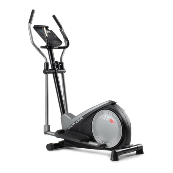
Thank you for selecting the new PROFORM manual. To help us assist you, note the product model ® CADENCE LE elliptical. The CADENCE LE elliptical number and serial number before contacting us. The provides a selection of features designed to make your model number and the location of the serial number workouts at home more effective and enjoyable. -
Page 6: Part Identification Chart
PART IDENTIFICATION CHART Use the drawings below to identify the small parts needed for assembly. The number in parentheses below each drawing is the key number of the part, from the PART LIST near the end of this manual. The number following the key number is the quantity needed for assembly. -
Page 7: Assembly
ASSEMBLY • To hire an authorized service technician to • In addition to the included tool(s), assembly assemble this product, call 1-800-445-2480. requires the following tools: one adjustable wrench • Assembly requires two persons. one Phillips screwdriver • Place all parts in a cleared area and remove the packing materials. - Page 8 3. Orient the Rear Stabilizer (9) as indicated by the sticker. While a second person lifts the rear of the Frame (1), attach the Rear Stabilizer (9) to the Frame with two M10 x 68mm Screws (34). 4. Orient the Upright (2) and the Top Shield (41) as shown.
- Page 9 5. See the inset drawing. Locate the wire tie (C) in the lower end of the Upright (2). Tie the wire tie to the Wire Harness (73). Next, pull the upper end of the wire tie until the Wire Harness is routed through the Upright.
- Page 10 7. While a second person holds the Console (23) near the Upright (2), plug the Wire Harness (73) and the Pulse Wires (84) into the receptacles (D) on the Console. The connectors on the Wire Harness (73) and the Pulse Wires (84) should slide easily into the receptacles (D) and snap into place.
- Page 11 9. Identify the Right Upper Body Arm (8). Slide an Upper Body Arm Cover (42) upward onto the Right Upper Body Arm (8). Next, insert the Right Upper Body Arm (8) into an Upper Body Leg (5). Tip: Have a second person hold the Upper Body Arm Cover (42) while you perform this action: Attach the Right Upper Body Arm (8) to the...
- Page 12 11. Orient an Upper Body Arm Spacer (47) as shown, and slide it onto the right side of the Pivot Axle (26). Next, slide the Right Upper Body Arm (8) onto the right side of the Pivot Axle (26). Repeat these actions on the other side of the elliptical.
- Page 13 13. Orient a Crank Arm Stud (32) as shown, and tighten it firmly into the Right Crank Arm (80). IMPORTANT: Make sure that the Crank Arm Stud is firmly tightened. Then, tighten an M6 x 8mm Set Screw (89) into the Right Crank Arm (80) and the Crank Arm Stud (32).
- Page 14 15. See assembly steps 4 and 5. Tighten the M10 x 20mm Screws (40) and the M10 Locknut (33). Then, press the Top Shield (41) into place. Next, apply a small amount of grease to an M6 Bolt Set (25). Hold the end of the Right Pedal Arm (12) inside the bracket on the right Upper Body Leg (5).
- Page 15 17. IMPORTANT: You must activate your Console (23) to begin using its exclusive features. First, press any button on the Console (23) to turn on the power. Then, using your smartphone or tablet, go to iFit.com/activate and follow the instructions to activate the Console (23).
-
Page 16: How To Use The Elliptical
HOW TO USE THE ELLIPTICAL HOW TO PLUG IN THE POWER ADAPTER HOW TO MOVE THE ELLIPTICAL IMPORTANT: If the elliptical has been exposed to Due to the size and weight of the elliptical, moving cold temperatures, allow it to warm to room tem- it requires two persons. - Page 17 HOW TO EXERCISE ON THE ELLIPTICAL To dismount the elliptical, wait until the pedals (G) come to a complete stop. Note: The elliptical does To mount the elliptical, hold the handlebars (E) or the not have a free wheel; the pedals will continue to move until the flywheel stops.
-
Page 18: How To Use The Console
HOW TO USE THE CONSOLE CONSOLE DIAGRAM FEATURES OF THE CONSOLE The console also offers a selection of onboard work- outs. Each onboard workout automatically changes the IMPORTANT: To activate your console and begin resistance of the pedals and prompts you to maintain using its exclusive features, see assembly step 17 a target pedaling speed as it guides you through an on page 15. - Page 19 HOW TO USE THE MANUAL MODE Distance (DIST.)—The distance that you have pedaled in miles or kilometers. To change the unit 1. Begin pedaling or press any button on the of measurement, press the St/M button. console to turn on the console. Heart Rate (heart symbol)—Your heart rate when When you turn on the console, the display will turn you use the handgrip heart rate monitor or a com-...
- Page 20 To pause the console, simply stop pedaling or palms resting against the contacts. Avoid moving press the End button. When the console is paused, your hands or gripping the contacts tightly. the time will flash in the display. To continue your workout, simply resume pedaling.
- Page 21 HOW TO USE AN ONBOARD WORKOUT IMPORTANT: The target speed is intended only to provide motivation. Your actual pedaling 1. Begin pedaling or press any button on the speed may be slower than the target speed. console to turn on the console. Make sure to pedal at a speed that is comfort- able for you.
- Page 22 HOW TO CONNECT YOUR TABLET TO THE 4. Record and track your workout information. CONSOLE Follow the instructions in the iFit–Smart Cardio The console supports Bluetooth connections to tab- Equipment app to record and track your workout lets via the iFit–Smart Cardio Equipment app and to information.
- Page 23 HOW TO CHANGE CONSOLE SETTINGS Demo Mode—The currently selected 1. Select the settings mode. demo mode option will appear in the display. To select the settings mode, press the Settings The console features a button (gear symbol). The first settings screen will demo mode, designed appear in the display.
-
Page 24: Fcc Information
FCC INFORMATION This equipment has been tested and found to comply with the limits for a Class B digital device, pursuant to Part 15 of the FCC Rules. These limits are designed to provide reasonable protection against harmful interference in a residential installation. This equipment generates, uses, and can radiate radio frequency energy and, if not installed and used in accordance with the instructions, may cause harmful interference to radio communications. -
Page 25: Maintenance And Troubleshooting
MAINTENANCE AND TROUBLESHOOTING MAINTENANCE Note: For clarity, the right pedal disc is not shown in the drawing below. Regular maintenance is important for optimal performance and to reduce wear. Inspect and properly Locate the Reed Switch (53). Slightly loosen the tighten all parts each time the elliptical is used. - Page 26 HOW TO ADJUST THE DRIVE BELT Next, loosen the M8 x 22mm Screw (65), and turn the M10 x 60mm Bolt (62) until the Drive Belt (19) is tight. If you feel the pedals slip while you are pedaling, even when the resistance is adjusted to the highest level, the drive belt may need to be adjusted.
-
Page 27: Exercise Guidelines
EXERCISE GUIDELINES Burning Fat—To burn fat effectively, you must exer- WARNING: cise at a low intensity level for a sustained period of Before beginning this time. During the first few minutes of exercise, your or any exercise program, consult your physi- body uses carbohydrate calories for energy. - Page 28 SUGGESTED STRETCHES The correct form for several basic stretches is shown at the right. Move slowly as you stretch; never bounce. 1. Toe Touch Stretch Stand with your knees bent slightly and slowly bend forward from your hips. Allow your back and shoulders to relax as you reach down toward your toes as far as possible.
-
Page 29: Part List
PART LIST Model No. PFEL62919.0 R0919A Key No. Qty. Description Key No. Qty. Description Frame Upper Body Arm Spacer Upright Frame Spacer Left Shield Upper Body Arm Bushing Right Shield M8 x 41mm Bolt Upper Body Leg M10 x 22mm Washer Left Upper Body Arm M4 x 16mm Screw M10 x 77mm Bolt... -
Page 30: Exploded Drawing
EXPLODED DRAWING A Model No. PFEL62919.0 R0919A 33 88... - Page 31 EXPLODED DRAWING B Model No. PFEL62919.0 R0919A 40 83...
-
Page 32: Ordering Replacement Parts
ORDERING REPLACEMENT PARTS To order replacement parts, please see the front cover of this manual. To help us assist you, be prepared to provide the following information when contacting us: • the model number and serial number of the product (see the front cover of this manual) •...
Need help?
Do you have a question about the CADENCE LE and is the answer not in the manual?
Questions and answers
Does it have FTMS bluetooth compatibility? i **** trying to find out if i need to purchase a cadence sensor to connect to holofit.
The manual mentions Bluetooth connectivity for heart rate monitors and tablet connections but does not specify FTMS Bluetooth compatibility. It also does not mention the need for a separate cadence sensor to connect to Holofit. Therefore, the answer to both parts of the question cannot be determined from the provided information.
This answer is automatically generated
How to reset resistance?