Advertisement
Table of Contents
- 1 Table of Contents
- 2 Warning Decal Placement
- 3 Important Precautions
- 4 Before You Begin
- 5 Part Identification Chart
- 6 Assembly
- 7 How to Use the Elliptical
- 8 How to Use the Console
- 9 Fcc Information
- 10 Maintenance and Troubleshooting
- 11 Exercise Guidelines
- 12 Part List
- 13 Exploded Drawing
- 14 Ordering Replacement Parts
- 15 Limited Warranty
- Download this manual
proform.com
Model No. PFEL55921.0
Serial No.
Write the serial number in the space
above for reference.
Serial Number
Decal
REGISTER YOUR
PRODUCT
To register your product and
activate your warranty today,
go to my.proform.com.
MEMBER CARE
For service at any time, go to
support.proform.com.
Or call 1-833-680-IFIT
(1-833-680-4348)
Mon.–Fri. 6 a.m.–6 p.m. MT
Sat. 8 a.m.–12 p.m. MT
Please do not contact the store.
CAUTION
Read all precautions and
instructions in this manual before
using this equipment. Keep this
manual for future reference.
USER'S MANUAL
Advertisement
Table of Contents

Related Manuals for Pro-Form CARBON EL


Summary of Contents for Pro-Form CARBON EL
- Page 1 proform.com Model No. PFEL55921.0 Serial No. USER’S MANUAL Write the serial number in the space above for reference. Serial Number Decal REGISTER YOUR PRODUCT To register your product and activate your warranty today, go to my.proform.com. MEMBER CARE For service at any time, go to support.proform.com.
-
Page 2: Table Of Contents
TABLE OF CONTENTS WARNING DECAL PLACEMENT ............. . .2 IMPORTANT PRECAUTIONS . -
Page 3: Important Precautions
IMPORTANT PRECAUTIONS WARNING: To reduce the risk of serious injury, read all important precautions and instructions in this manual and all warnings on your elliptical before using your elliptical. ICON assumes no responsibility for personal injury or property damage sustained by or through the use of this product. - Page 4 STANDARD SERVICE PLANS...
-
Page 5: Before You Begin
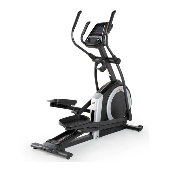
Thank you for selecting the revolutionary PROFORM reading this manual, please see the front cover of this CARBON EL elliptical. The CARBON EL elliptical manual. To help us assist you, note the product model provides an impressive selection of features designed number and serial number before contacting us. -
Page 6: Part Identification Chart
PART IDENTIFICATION CHART Use the drawings below to identify the small parts needed for assembly. The number in parentheses below each drawing is the key number of the part, from the PART LIST near the end of this manual. The number following the key number is the quantity needed for assembly. -
Page 7: Assembly
ASSEMBLY 1. To use the assembly steps in this manual, first see the helpful tips below. • To hire an authorized service technician to • In addition to the included tool(s), assembly assemble this product, call 1-800-445-2480. requires the following tools: one Phillips screwdriver •... - Page 8 3. With the help of a second person, place some of the packing materials (not shown) under the front of the Frame (1). Have the second per- son hold the Frame to prevent it from tipping while you complete this step. Attach the Front Stabilizer (6) to the Frame (1) with two M10 x 115mm Screws (104).
- Page 9 5. Tip: Avoid pinching the Upper Wire (110). Have a second person hold the Upright (4) on the Frame (1). Avoid pinching the Tip: Two M10 x 25mm Screws (92) are Upper Wire (110) preattached to the Frame (1). Attach the Upright (4) to the Frame (1) with two additional M10 x 25mm Screws (92);...
- Page 10 7. Apply grease to the axle on the right side of the Upright (4). Next, slide a Pivot Spacer (54) onto the right side of the Upright (4). Then, identify the Right Upper Body Leg (60), orient it as shown, and slide it onto the right side of the Upright (4).
- Page 11 9. Apply grease to one of the Pedal Arm Axles (64). Insert the Pedal Arm Axle (64) into the Right Upper Body Leg (60) and the Right Pedal Arm (58) from the direction shown. Next, slide an M8 x 22mm Washer (129) onto an M8 x 13mm Screw (82), and tighten the Screw a few turns into the Pedal Arm Axle (64).
- Page 12 11. Orient the Rear Console Cover (80) as shown, and attach it to the Upright (4) with two M4 x 16mm Screws (101). Then, orient the Front Console Cover (79) as shown, and attach it to the Rear Console Cover (80) with two M4 x 16mm Screws (101).
- Page 13 13. Orient a Lower Tray Cover (81) as shown, and attach it to the right side of the Accessory Tray (37) with two M4 x 16mm Screws (101). Repeat this step on the other side of the elliptical. 14. Identify the Right Upper Body Arm (61), orient it as shown, and slide it onto the Right Upper Body Leg (60).
- Page 14 15. Orient the Front Shield Cover (117) and the Center Shield Cover (75) around the Upright (4) as shown. Then, attach them to each other with two M4 x 16mm Screws (101). Then, press the Front Shield Cover (117) and the Center Shield Cover (75) into the Left and Right Shields (73, 74).
- Page 15 17. Orient the Right Arm Front and Rear Covers (65, 66) around the Right Upper Body Leg (60) as shown, and then attach them with two M4 x 16mm Screws (101). Repeat this step on the other side of the elliptical.
- Page 16 19. IMPORTANT: You must activate your Console (7) to begin using its exclusive features. First, press any button on the Console (7) to turn on the power. Then, using your smartphone or tablet, go to iFIT.com/activate and follow the instructions to activate the Console (7).
-
Page 17: How To Use The Elliptical
HOW TO USE THE ELLIPTICAL HOW TO PLUG IN THE POWER ADAPTER HOW TO MOVE THE ELLIPTICAL IMPORTANT: If the elliptical has been exposed to Due to the size and weight of the elliptical, moving cold temperatures, allow it to warm to room tem- it requires two persons. - Page 18 HOW TO LEVEL THE ELLIPTICAL HOW TO EXERCISE ON THE ELLIPTICAL If the elliptical rocks slightly on your floor during use, To mount the elliptical, hold the handlebars (J) or the turn one or both of the leveling feet (F) beneath the upper body arms (K) and step onto the pedal (L) that is rear stabilizer or turn the leveling foot (G) under in the lower position.
-
Page 19: How To Use The Console
HOW TO USE THE CONSOLE CONSOLE DIAGRAM FEATURES OF THE CONSOLE The console also offers unlimited iFIT workouts when you download the iFIT app to your smart device and IMPORTANT: To activate your console and begin connect it to the console. using its exclusive features, see assembly step 19 on page 16. - Page 20 HOW TO USE THE MANUAL MODE Distance (MI or KM)—The distance that you have pedaled in miles or kilometers. To change the unit 1. Begin pedaling or press any button on the of measurement, press the Std/Met button. console to turn on the console. Pace—Your pedaling speed in minutes per mile When you turn on the console, the display will turn or minutes per kilometer.
- Page 21 To manually advance the scan cycle, press the 5. Wear a compatible heart rate monitor and Multi-scan button repeatedly. measure your heart rate if desired. To turn off the scan mode, press the Display You can wear a compatible heart rate monitor to button;...
- Page 22 HOW TO USE AN IFIT WORKOUT 4. Select an iFIT workout. The console offers access to a large and varied library In the iFIT app, touch the buttons at the bottom of of iFIT workouts when you download the iFIT app to the screen to select either the home screen (Home your smart device and connect it to the console.
- Page 23 To pause the workout, simply touch the screen HOW TO CONNECT YOUR HEART RATE MONITOR or stop pedaling. To continue the workout, sim- TO THE CONSOLE ply resume pedaling. The console is compatible with all Bluetooth Smart To end the workout, touch the screen to pause the heart rate monitors.
- Page 24 HOW TO USE THE SOUND SYSTEM THE OPTIONAL HEART RATE MONITOR To play music or audio books through the console Whether your sound system while you exercise, plug a 3.5 mm male goal is to to 3.5 mm male audio cable (not included) into the burn fat or to jack on the console and into a jack on your personal strengthen your...
- Page 25 HOW TO CHANGE CONSOLE SETTINGS Total Time—The word TIME will appear in the display. The display will show the total number of 1. Select the settings mode. hours that the elliptical has been used. To select the settings mode, press the Settings button.
-
Page 26: Fcc Information
FCC INFORMATION This equipment has been tested and found to comply with the limits for a Class B digital device, pursuant to Part 15 of the FCC Rules. These limits are designed to provide reasonable protection against harmful interference in a residential installation. This equipment generates, uses, and can radiate radio frequency energy and, if not installed and used in accordance with the instructions, may cause harmful interference to radio communications. -
Page 27: Maintenance And Troubleshooting
MAINTENANCE AND TROUBLESHOOTING MAINTENANCE Locate the Reed Switch (38). Turn the Pulley (19) until a Magnet (43) is aligned with the Reed Switch. Regular maintenance is important for optimal performance and to reduce wear. Inspect and properly tighten all parts each time the elliptical is used. - Page 28 HOW TO ADJUST THE DRIVE BELT Next, locate and loosen the If the pedals slip while you are pedaling, even while Idler Screw (89). the resistance is adjusted to the highest level, the drive Tighten the Drive belt may need to be adjusted. To adjust the drive belt, Belt Adjustment first unplug the power adapter.
-
Page 29: Exercise Guidelines
EXERCISE GUIDELINES Aerobic Exercise—If your goal is to strengthen your WARNING: cardiovascular system, you must perform aerobic Before beginning this exercise, which is activity that requires large amounts or any exercise program, consult your physi- of oxygen for prolonged periods of time. For aerobic cian. - Page 30 SUGGESTED STRETCHES The correct form for several basic stretches is shown at the right. Move slowly as you stretch; never bounce. 1. Toe Touch Stretch Stand with your knees bent slightly and slowly bend forward from your hips. Allow your back and shoulders to relax as you reach down toward your toes as far as possible.
-
Page 31: Part List
PART LIST Model No. PFEL55921.0 R0821A Key No. Qty. Description Key No. Qty. Description Frame/Ramp Roller Rear Stabilizer Pedal Arm Cap Access Cover Axle Cover Upright Pivot Spacer M4 x 19mm Screw Retainer Front Stabilizer Roller Arm Bushing Console Outer Arm Bearing Roller Guide Right Pedal Arm Crank Bearing Sleeve... - Page 32 Key No. Qty. Description Key No. Qty. Description M4 x 16mm Screw Rear Shield Cover M8 Locknut Power Adapter M6 x 12mm Screw M8 x 20mm Flat Head Screw M10 x 115mm Screw Latch Axle M4 x 25mm Self-tapping Screw Pin Spring Bottom Ramp Cover Small Arm Bearing...
-
Page 33: Exploded Drawing
EXPLODED DRAWING A Model No. PFEL55921.0 R0821A... - Page 34 EXPLODED DRAWING B Model No. PFEL55921.0 R0821A...
- Page 35 EXPLODED DRAWING C Model No. PFEL55921.0 R0821A...
-
Page 36: Ordering Replacement Parts
ORDERING REPLACEMENT PARTS To order replacement parts, please see the front cover of this manual. To help us assist you, be prepared to provide the following information when contacting us: • the model number and serial number of the product (see the front cover of this manual) •...
Need help?
Do you have a question about the CARBON EL and is the answer not in the manual?
Questions and answers
top of the machine has become lose while using