Table of Contents
Advertisement
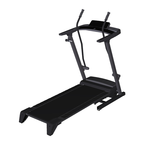
proform.com
Model No. PFTL29820.0
Serial No.
Write the serial number in the space
above for reference.
Serial
Number
Decal
REGISTER YOUR
PRODUCT
To register your product and
activate your warranty today,
go to my.proform.com.
MEMBER CARE
For service at any time, go to
support.proform.com.
Or call 1-833-680-IFIT
(1-833-680-4348)
Mon.–Fri. 6 a.m.–6 p.m. MT
Sat. 8 a.m.–12 p.m. MT
Please do not contact the store.
CAUTION
Read all precautions and
instructions in this manual before
using this equipment. Keep this
manual for future reference.
USER'S MANUAL
Advertisement
Table of Contents

Related Manuals for Pro-Form CrossWalk LT


Summary of Contents for Pro-Form CrossWalk LT
- Page 1 proform.com Model No. PFTL29820.0 USER’S MANUAL Serial No. Write the serial number in the space above for reference. Serial Number Decal REGISTER YOUR PRODUCT To register your product and activate your warranty today, go to my.proform.com. MEMBER CARE For service at any time, go to support.proform.com.
-
Page 2: Table Of Contents
TABLE OF CONTENTS WARNING DECAL PLACEMENT ............. . .2 IMPORTANT PRECAUTIONS . -
Page 3: Important Precautions
IMPORTANT PRECAUTIONS WARNING: To reduce the risk of burns, fire, electric shock, or injury to persons, read all important precautions and instructions in this manual and all warnings on your treadmill before using your treadmill. ICON assumes no responsibility for personal injury or property damage sus- tained by or through the use of this product. - Page 4 19. Read, understand, and test the emergency on page 8 and HOW TO FOLD AND MOVE stop procedure before using the treadmill THE TREADMILL on page 25.) You must be (see HOW TO TURN ON THE POWER on able to safely lift 45 lbs. (20 kg) to move the page 18).
- Page 5 STANDARD SERVICE PLANS...
-
Page 6: Before You Begin
Thank you for selecting the new PROFORM using the treadmill. If you have questions after read- ® CROSSWALK LT treadmill. The CROSSWALK LT ing this manual, please see the front cover of this treadmill offers a selection of features designed to manual. -
Page 7: Part Identification Chart
PART IDENTIFICATION CHART Use the drawings below to identify small parts used for assembly. The number in parentheses below each drawing is the key number of the part, from the PART LIST near the end of this manual. The number following the key number is the quantity used for assembly. -
Page 8: Assembly
ASSEMBLY 1. To use the assembly steps in this manual, first see the helpful tips below. • To hire an authorized service technician to • Left parts are marked “L” or “Left” and right parts assemble the treadmill, call 1-800-445-2480. are marked “R”... - Page 9 3. Identify the Rear Base Crossbar (76) by the Thin Base Pads (78) attached to its top. Attach the Rear Base Crossbar (76) to the Left Base Leg (73) with two M8 x 19mm Screws (8); do not fully tighten the Screws yet. Next, identify the Front Base Crossbar (75) and orient it so that the “this side up”...
- Page 10 6. Identify the Left and Right Handrail Bottoms (64, 65) and slide them onto the Left and Right Uprights (69, 70) as shown. With the help of a second person, attach the handrail assembly (A) to the Uprights (69, 70) with four M10 x 45mm Screws (2) and four M10 Star Washers (13);...
- Page 11 8. Identify the Right Handrail Top (63). Set the Right Handrail Top on the Handrail (66) and slide it forward against the Console Base (84). Next, slide the Right Handrail Bottom (65) upward. Make sure that the Upright Wire (see step 7) is covered by the Right Handrail Bottom and is not pinched.
- Page 12 10. Lay the Walking Platform (35) on a soft surface to avoid scratching the Walking Platform. Make sure that the Latch Plate (33) is on the top surface. Start four M4.2 x 13mm Screws (5) in the loca- tions shown. Do not fully tighten the Screws; leave about a 1/8"...
- Page 13 13. Raise the Walking Platform (35) to the storage position (see HOW TO FOLD THE TREADMILL on page 25). Next, orient a Belt Guide (38) as shown, and set it over the M4.2 x 13mm Screws (5) that you started in step 10. Slide the Belt Guide toward the center of the Walking Platform (35) as far as the Screws will allow.
- Page 14 16. Center the Walking Belt (36) on the Walking Platform (35). IMPORTANT: Keep hands, clothing, and other objects away from the Right and Left Roller Brackets (47, 48) during this step. Grasp the center (D) of the Idler Roller (50) and the Walking Belt (36) firmly with both hands.
- Page 15 19. Identify the Left Upper Body Arm (91). Orient the Left Upper Body Arm as shown, and insert the lower end into the Resistance Assembly (95); make sure that the lower end of the Upper Body Arm slightly protrudes from the bottom of the Resistance Assembly.
-
Page 16: How To Use The Treadmill
HOW TO USE THE TREADMILL HOW TO CONNECT THE POWER CORD capable of carrying 15 or more amps. To avoid overloading the circuit, do not plug other electrical Use a Surge Suppressor devices, except for low-power devices such as cell phone chargers, into the surge suppressor or into Your treadmill, like other electronic equipment, can be an outlet on the same circuit. - Page 17 CONSOLE DIAGRAM FEATURES OF THE CONSOLE To turn on the power, see page 18. To use the man- ual mode, see page 18. To use an onboard workout, IMPORTANT: To activate your console and begin see page 21. To connect your tablet to the console, using its exclusive features, see assembly step 20 see page 22.
- Page 18 HOW TO TURN ON THE POWER HOW TO USE THE MANUAL MODE IMPORTANT: If the treadmill has been exposed to 1. Insert the key into the console. cold temperatures, allow it to warm to room tem- perature before you turn on the power. If you do See HOW TO TURN ON THE POWER at the left.
- Page 19 4. Follow your progress with the displays. The Display button (L) can be used to select which When you select the information is shown in the manual mode, a track upper display. representing 1/4 mile (400 m) will appear in To reset the displays, press the matrix.
- Page 20 6. Measure your heart rate if desired. If the displayed heart rate appears to be too high or too low, or if your heart rate is not displayed, lift You can measure your heart rate using either the your thumb for a few seconds, and then reposition thumb heart rate monitor or a compatible heart rate your thumb on the heart rate monitor.
- Page 21 HOW TO USE AN ONBOARD WORKOUT The workout will continue in this way until the last segment of the profile flashes and the last segment 1. Insert the key into the console. ends. The walking belt will then slow to a stop. See HOW TO TURN ON THE POWER on page 18.
- Page 22 HOW TO CONNECT YOUR TABLET TO THE 5. Disconnect your tablet from the console if CONSOLE desired. The console supports Bluetooth connections to tablets To disconnect your tablet from the console, first via the iFIT app and to compatible heart rate monitors. select the disconnect option in the iFIT app.
- Page 23 THE INFORMATION MODE Demo Mode—The currently selected demo mode option will appear in the display. The console The console features an information mode that keeps features a demo mode, designed to be used if the track of treadmill usage information and allows you to treadmill is displayed in a store.
-
Page 24: Fcc Information
FCC INFORMATION This console has been tested and found to comply with the limits for a Class B digital device, pursuant to part 15 of the FCC Rules. These limits are designed to provide reasonable protection against harmful interference in a residential installation. This equipment generates, uses, and can radiate radio frequency energy and, if not installed and used in accordance with the instructions, may cause harmful interference to radio communications. -
Page 25: How To Fold And Move The Treadmill
HOW TO FOLD AND MOVE THE TREADMILL HOW TO FOLD THE TREADMILL HOW TO MOVE THE TREADMILL Before folding the treadmill, remove the key and Before moving the treadmill, fold it as described at unplug the power cord. CAUTION: You must be the left. -
Page 26: Maintenance And Troubleshooting
MAINTENANCE AND TROUBLESHOOTING MAINTENANCE c. Check the power switch located on the treadmill frame near the power cord. If the switch protrudes Regular maintenance is important for optimal per- as shown (A), the switch has tripped. To reset the formance and to reduce wear. Inspect and properly power switch, wait for five minutes and then press tighten all parts each time the treadmill is used. - Page 27 SYMPTOM: The upper body arms squeak during SYMPTOM: The walking belt slows when walked on a. Use only a surge suppressor that meets all of the specifications described on page 16. a. (Note: Correcting this problem requires a small amount of marine grease, available at hardware b.
- Page 28 SYMPTOM: The walking belt is not centered SYMPTOM: The walking belt slips when walked on between the foot rails. b. First, remove the key and UNPLUG THE POWER a. Fold the treadmill into the storage position (see CORD. Using the hex key, turn both idler roller HOW TO FOLD AND MOVE THE TREADMILL on screws clockwise, 1/4 of a turn.
-
Page 29: Exercise Guidelines
EXERCISE GUIDELINES Burning Fat—To burn fat effectively, you must exer- cise at a low intensity level for a sustained period of WARNING: Before beginning this time. During the first few minutes of exercise, your or any exercise program, consult your physi- body uses carbohydrate calories for energy. - Page 30 SUGGESTED STRETCHES The correct form for several basic stretches is shown at the right. Move slowly as you stretch —never bounce. 1. Toe Touch Stretch Stand with your knees bent slightly and slowly bend forward from your hips. Allow your back and shoulders to relax as you reach down toward your toes as far as possible.
-
Page 31: Part List
PART LIST Model No. PFTL29820.0 R0721A Key No. Qty. Description Key No. Qty. Description M10 x 75mm Screw Idler Roller M10 x 45mm Screw Right Foot Cover M4.2 x 19mm Screw Left Foot Cover 1/4" Star Washer Hood Cover M4.2 x 13mm Screw Hood M10 x 70mm Bolt Controller... -
Page 32: Exploded Drawing
EXPLODED DRAWING A Model No. PFTL29820.0 R0721A... - Page 33 EXPLODED DRAWING B Model No. PFTL29820.0 R0721A...
- Page 34 EXPLODED DRAWING C Model No. PFTL29820.0 R0721A...
- Page 35 EXPLODED DRAWING D Model No. PFTL29820.0 R0721A...
-
Page 36: Ordering Replacement Parts
ORDERING REPLACEMENT PARTS To order replacement parts, please see the front cover of this manual. To help us assist you, be prepared to provide the following information when contacting us: • the model number and serial number of the product (see the front cover of this manual) •...
Need help?
Do you have a question about the CrossWalk LT and is the answer not in the manual?
Questions and answers