Ltech DMX512 Quick Start Manual
Hide thumbs
Also See for DMX512:
- Quick start manual (7 pages) ,
- Connection manual (7 pages) ,
- Instruction manual (22 pages)

Related Manuals for Ltech DMX512


Summary of Contents for Ltech DMX512
- Page 1 LT-905-OLED OLED display 8 bit / 16 bit 2 kinds of DMX interfaces Dimming curve: 0.1~9.9 Photoelectric CHANNELS isolation Short circuit / Over current / Overheat protection www.ltech-led.com...
-
Page 2: Product Introduction
Product introduction 1. Designed with 5 channels output, and Max. 5A per channel, up to 600W output. 2. Easy operation with OLED display and the touch buttons. 3. 5 modes available: DIM, CT, RGB, RGBW, RGBWY. 4. 5-pin XLR, RJ45 DMX interface with photoelectric isolation, improve signal transmission efficiency and anti-interference ability. -
Page 3: Technical Specs
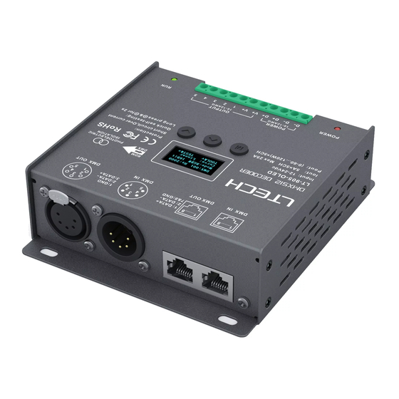
Technical specs Model Photoelectric LT-905-OLED isolation: Input signal DMX512/RDM Working temp. °C °C Input voltage 12 24Vdc Dimensions 122×110×37mm(L×W×H) Current load × 5CH Max. 25A Package size 127×123×41mm(L×W×H) Output power: (0~60W...120W) × 5CH Max. 600W Weight (G.W.) 550g DMX interfaces:... - Page 4 Main component description OLED display 5-pin XLR RJ45 DMX/RDM DMX/RDM input & output input & output Power 12-24Vdc Signal Green terminals indicator Power input LED lamp connection indicator OLED display interface Press "M" key, switch entries. Press "∧" or “∨" key, parameter adjustment.
- Page 5 2. PWM Press “∧" or “∨" key to choose. DMX: 001 High No flicker in frequency Option : Mode: RGB 8bit video camera. Curve: Standard Std (standard) Dim: Smo TOOL&v High Mid (middle) It is recommended to Smooth and delicate, use standard.
- Page 6 7. Tool DMX: 001 Hz: High Mode: RGBW 8bit Curve: Standard Dim: Smo TOOL&v Press “∧" or “∨" key to enter submenu Screen: ON+Addr Contrast: 40% Test Beep: ON TEST&v Press “∧" or “∨" EXIT&v key to enter submenu of test.
-
Page 7: Wiring Diagram
Wiring diagram 1. Connecting LED lights: DMX/RDM signal DMX/RDM signal DMX/RDM signal DMX/RDM signal LT-905-OLED LT-905-OLED Output port 12-24Vdc 12-24Vdc (Wiring method as follow) driver driver driver Dimming LEDs CT/CT2 LEDs Dimming mode mode RGBW LEDs RGB LEDs RGBW... - Page 8 2. DMX console onnection LT-905-OLED is equipped with 2 kinds of DMX terminals for users’ selection. The following diagram takes 5-pin XLR as an example, same connecting method for RJ45. console Resistor terminal DMX signal DMX signal DATA+ DATA-...
- Page 9 3. The connection diagram of 2 kinds of DMX/RDM terminals: Resistor terminal LT-905-OLED LT-905-OLED LT-905-OLED 5-pin XLR connected in parallel Resistor terminal Vent LT-905-OLED LT-905-OLED LT-905-OLED RJ45 connected in parallel Installation distance > 20mm These 2 terminals can be connected in a mixed way.
- Page 10 Address setting table Mode CT/CT2 RGBW RGBWY Address quantity Resolution 8bit 8bit 8bit 8bit 8bit Channel Mode CT/CT2 RGBW RGBWY Address quantity Resolution 16bit 16bit 16bit 16bit 16bit Channel When you select CT2, the DMX address represents brightness ,...
- Page 11 Work with RDM editor LT-905-OLED can work with LTECH RDM editor (Model: WiFi-RDM01) to realize changing the parameters by long-range setting, wiring diagram as below: 5-24Vdc Power WIFI-RDM01 input … … LT-905-OLED LT-905-OLED LT-905-OLED LT-905-OLED driver driver driver driver...
- Page 12 RDM editor App interface instruction Download the App, setting the LT-905-OLED parameters (frequency, bit, curve, modes, dimming range, screensaver, etc.) after well connecting the RDM editor, more details, please check the manual of WiFi-RDM01. Well installation of products first, then working with WiFi -RDM01 to realize setting parameters and firmware upgrade by App.
Need help?
Do you have a question about the DMX512 and is the answer not in the manual?
Questions and answers