Table of Contents
Advertisement
Quick Links
- 1 V-530 Uv/Vis Spectrophotometer Specifications
- 2 V-550 Uv/Vis Spectrophotometer Specifications
- 3 V-560 Uv/Vis Spectrophotometer Specifications
- 4 V-570 Uv/Vis/Nir Spectrophotometer Specifications
- 5 V-550/560/570 Spectrophotometers Optical System
- 6 Lamp Replacement and Adjusting the Light Source Mirror
- Download this manual
Advertisement
Table of Contents

Related Manuals for Jasco V-530


Summary of Contents for Jasco V-530
- Page 1 (217) 352-9330 | Click HERE Find the Jasco V-530 at our website:...
- Page 2 Model V-530/550/560/570 UV/VIS Spectrophotometer Hardware/Function Manual P/N:0302-0256B November 2000 Artisan Technology Group - Quality Instrumentation ... Guaranteed | (888) 88-SOURCE | www.artisantg.com...
- Page 3 Safety Considerations To ensure operation safety, this instrument must be operated correctly and maintained regularly according to schedule. Carefully read to fully understand all safety precautions in this manual before operating the instrument. This manual denotes precautions against actions that can result in hazardous situations or equipment damage by using the signal words WARNING, CAUTION, and Note.
- Page 4 Warning labels are attached at several locations on this instrument. Do not remove, deface or damage the warning labels. If a warning label peels off the instrument or becomes illegible, contact your local JASCO distributor for a replacement label. Be sure to indicate the part number on the label.
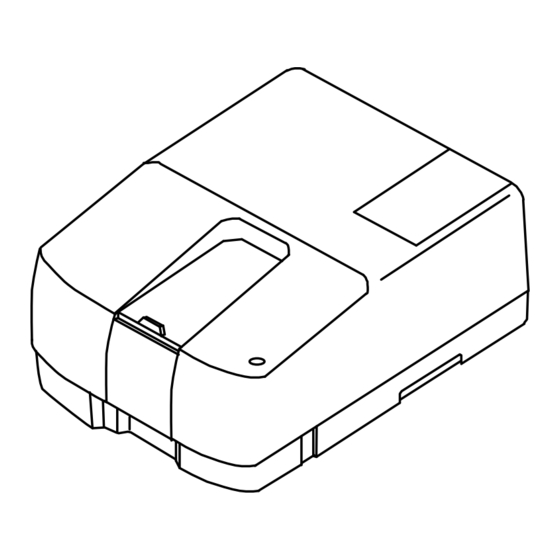
- Page 5 Warning for FUSE Fig. 2 Warning Labels on the V-550/560/570 Rear Panel Warning for carrying These instruments weigh as follows: V-530: 16.0 kg V-550: 30.5 kg V-560: 32.0 kg V-570: 33.0 kg When carrying the instrument, hold the carrying handle at the bottom of the instrument firmly (See Fig 3).
-
Page 6: Regulatory Statements
• A “Declaration of Conformity” in accordance with the above standards has been made and is on file at JASCO EUROPE srl, Via Confalonieri 25, 22060 CREMELLA (Lc), Italy. FCC Statement (for USA only) -
Page 7: Preface
When not using the instrument, keep this manual stored in a safe place. Should this instruction manual be lost, order a replacement from your local JASCO distributor. This manual is made up of the following parts. -
Page 8: Installation Conditions
Installation Conditions To ensure operation safety, observe the following conditions: Do not operate the instrument under voltage fluctuations exceeding 10% of the recommended line voltage. Otherwise, the instrument may not function properly. Use a three-prong electrical outlet with a ground. Operate the instrument in a temperature range of 10 °∼... -
Page 9: Servicing
JASCO distributor before moving the instrument to another location. Consumable parts should be ordered according to part numbers from your local JASCO distributor. If a part number is unknown, give your JASCO distributor the model name and serial number of your instrument. -
Page 10: Limited Warranty
If any defects in the product are found during this warranty period, JASCO will repair or replace the defective part(s) or product free of charge. THIS WARRANTY DOES NOT APPLY TO DEFECTS RESULTING FROM THE... -
Page 11: Table Of Contents
SAFETY CONSIDERATIONS......................I REGULATORY STATEMENTS....................IV PREFACE............................. V INSTALLATION CONDITIONS ....................VI SERVICING ..........................VII LIMITED WARRANTY......................VIII 1 SPECIFICATIONS........................1 ............1 1.1 V-530 UV/VIS S PECTROPHOTOMETER PECIFICATIONS ............2 1.2 V-550 UV/VIS S PECTROPHOTOMETER PECIFICATIONS ............3 1.3 V-560 UV/VIS S... -
Page 12: Specifications
1 Specifications The specifications of each model covered in this manual are given below. Refer to the Operations manual for software specifications. 1.1 V-530 UV/VIS Spectrophotometer Specifications Optical system Single monochromator UV/VIS region: 1200 lines/mm concave grating Rowland off-circle arrangement... -
Page 13: V-550 Uv/Vis Spectrophotometer Specifications
(value obtained more than one hour after turning ON the power when temperature variation is within 5°C, wavelength: 250 nm, and response: Slow.) ±0.001 Abs Baseline flatness (value obtained after baseline correction when temperature variation within 5°C, wavelength: 200 to 1100 nm, response: Medium, wavelength scanning:... -
Page 14: V-560 Uv/Vis Spectrophotometer Specifications
±0.002 Abs (0.5 to 1 Abs) ±0.002 Abs (0 to 0.5 Abs) Photometric accuracy ±0.004 Abs (0.5 to 1 Abs) ±0.3 %T Note: Tested with NIST SRM 930D Response Quick, Fast, Medium, Slow Stray light 0.015 % (220 nm: NaI 10g/L aqueous solution; 340 nm: NaNO 50g/L aqueous solution) Wavelength scanning... - Page 15 Light source Deuterium lamp: 190 to 350 nm Halogen lamp: 330 to 900 nm Light source changeover Any wavelength between 330 and 350 nm can wavelength be selected. Wavelength range 190 to 900 nm ±0.1 nm (at a spectral bandwidth of 0.5 nm) Wavelength repeatability ±0.3 nm (at a spectral bandwidth of 0.5 nm) Wavelength accuracy...
-
Page 16: V-570 Uv/Vis/Nir Spectrophotometer Specifications
Dimensions and weight 460(W)×595(D)×260(H)mm (excluding protrusions) 32 kg Note: Photometric repeatability, photometric accuracy and baseline flatness are the values obtained more than one hour after the “Power” switch is turned ON. 1.4 V-570 UV/VIS/NIR Spectrophotometer Specifications Optical system Single monochromator UV/VIS region: 1200 lines/mm plane grating NIR region: 300 lines/mm plane grating Czerny-Turner mount... - Page 17 ±0.004 Abs (0.5 to 1 Abs) ±0.3 %T Note: Tested with NIST SRM 930D Response Quick, Fast, Medium, Slow Stray light UV/VIS region: 0.015% (220 nm: NaI 10g/L aqueous solution; 340 nm: NaNO 50g/L aqueous solution) NIR region: 0.1% (1690 nm: CH 10 mm cell used) Wavelength scanning speed 10, 20, 40, 100, 200, 400, 1000, 2000, 4000...
-
Page 18: General Description Of Instrument
2.1.1 Optical System The V-530 is designed to measure the absorption spectrum of a sample at wavelengths in the range 190 to 1100 nm. The light sources used in the V-530 are a deuterium(D ) lamp (190 to 350 nm) for the UV region and a halogen (WI) lamp (340 to 1100 nm) for the VIS/NIR region. - Page 19 320×240 ROM, RAM Touch key 10×6 キー RAM Card Autozero Goto WL File Start Print Stop Battery Centronics Serial 1 Power supply Fig. 2.2 V-530 Electrical system Artisan Technology Group - Quality Instrumentation ... Guaranteed | (888) 88-SOURCE | www.artisantg.com...
-
Page 20: V-550/560/570 Spectrophotometers Optical System
2.2 V-550/560/570 Spectrophotometers Optical System 2.2.1 Optical System Figures 2.3 through 2.5 show the optical systems of the V-550, V-560 and V–570 spectrophotometers, respectively. The V-550 and V-560 measure the absorption spectrum of a sample at wavelengths in the range 190 to 900 nm and the V-570 measures the absorption spectrum of a sample at wavelengths in the range 190 to 2500 nm. - Page 21 WI, D : Light source M : Mirror S : Slit F : Filter G : Grating M8 : beam splitter PM : Detector Sam : Sample beam Ref : Reference beam W : window Fig 2.4 V-560 Optical system WI, D : Light source M : Mirror...
-
Page 22: Electrical System
2.2.2 Electrical System Figure 2.6 shows the configuration of the electrical system used in the V-550, V- 560 and V-570. The light incident on the photomultiplier tube or Pbs photoconductive cell is converted into an electrical signal and, after being synchronously rectified, is converted into digital form and enters the microcomputer. -
Page 23: Nomenclature And Functions Of Components
3 Nomenclature and Functions of Components 3.1 V-530 Spectrophotometer: Overview 3.1.1 Overview Sample chamber Light source lid "Power" switch Fixing screw Indicator lamp Fig. 3.1 Overview Component Function Sample chamber Slide the lid to open and gain access to the reference and sample cell holders. -
Page 24: Rear Panel
"Serial A" "iRM PS" "Serial B" "AUX" "Recorder" "Fuse" "AC Inlet" "GND" Warning label Fig. 3.2 V-530 rear panel Component Function AC Inlet Accepts the power cable. Grounding terminal Fuse Fuses for the main unit (two time-lag fuses) iRM PS Accepts the remote module power cable. -
Page 25: V-550/560/570 Spectrophotometers: Overview
3.2 V-550/560/570 Spectrophotometers: Overview 3.2.1 Overview Sample chamber Light source lid Indicotor lamp Fixing screw "Power" switch Pbs power supply unit Fig. 3.3 V-550/560/570 overview Component Function Sample chamber Slide the lid to open and gain access to the reference and sample cell holders. -
Page 26: Rear Panel
3.2.2 Rear Panel "iRM PS" "Recorder" "Serial A" Warning label "Serial B" "Aux" "AC Inlet" "GND" "Fuse" Fig. 3.4 V-550/560/570 Rear panel Component Function AC Inlet Accepts the power input cable. Ground terminal Fuse Fuses for the main unit (two time-lag fuses) iRM PS Accepts the remote module power cable. -
Page 27: Standard Sample Chamber
3.3 Standard Sample Chamber Sample cell holder Reference cell holder Cell pocket Not provided for the V-530. Fixing screw Fig. 3.5 Standard Sample Chamber Component Function Fixing screws Fix the sample chamber in position. To mount the optional sample chamber, loosen these screws and remove the standard sample chamber. -
Page 28: Intelligent Remote Module
3.4 Intelligent Remote Module Display panel Operation panel Card slot Overview "Contrast" "Printer" "Serial A" Power cable Rear panel Fig. 3.6 Intelligent remote module Component Function Display panel 320x240 pixel LCD. Displays wavelength, absorbance, measurement parameters, etc. Also used for selecting menus, and editing measurement parameters via the touch key pad. -
Page 29: Maintenance
4 Maintenance This section contains instructions on how to clean the sample chamber when a sample is spilt, how to run the performance check to see if the instrument is operating normally, and on replacing consumables. Give consideration to the environment in which the instrument is to be operated. Keep the instrument and surrounding area clean so that the spectrophotometer may be used in a stabilized condition over a long period. -
Page 30: Performance Check: Data Station Type
This check should be performed more than one hour after turning the instrument (1) Start the [Spectrum Measurement] program from the [Spectra Manager] window. (2) Click [Measurement]-[Spectrum Parameters...] and set parameters as follows: V-530 measurement parameters V-550/560/570 measurement Artisan Technology Group - Quality Instrumentation ... Guaranteed | (888) 88-SOURCE | www.artisantg.com... - Page 31 A measurement example is shown in Fig 4.1. (5) The baseline flatness is normal if the measurement result is within the following criterion. Within ±0.001 Abs (1000 ~ 200 nm) <V-530 criterion> Within ±0.001 Abs (850 ~ 200 nm) <V-550/560/570 criterion>...
-
Page 32: Wavelength Repeatability
Click <OK> to close the dialog box. Only the D lamp is lit. (2) Start [Spectrum Measurement] from the [Spectra Manager] window and set the following parameters. V-530 Measurement parameters V-550/560/570 measurement Artisan Technology Group - Quality Instrumentation ... Guaranteed | (888) 88-SOURCE | www.artisantg.com... - Page 33 parameters Photometric Mode Sample Photometric Mode Sample Response Fast Response Fast Scanning Speed 40 nm/min Band Width 0.5 nm Start 658 nm Scanning Speed 10 nm/min 654 nm Start 658 nm Data Pitch 0.1 nm 654 nm Display 0~100 Data Pitch 0.025 nm No of Cycles Display...
-
Page 34: Wavelength Accuracy
(1) Light only the Deuterium lamp (see item (1) in Section 4.3.2). (2) Start [Spectrum Measurement] from the [Spectra Manager] window and set the following parameters. <<Parameters for spectrum with an emission line at 656.1 nm>> V-530 measurement parameters V-550/560/570 measurement parameters... - Page 35 486.0 nm (4) Wavelength accuracy is normal if the measurement result in within the following criteria. Within 656.1 ± 0.5 nm <V-530 criteria> Within 486.0 ± 0.5 nm Within 656.1 ± 0.3 nm <V-550/560/570 criteria>...
-
Page 36: Performance Check : Intelligent Remote Module Type
(2) Set the following parameter and measure the baseline spectrum (0 Abs line) with the sample chamber empty. (Refer to Section 5-3 of the Operations manual.) A measurement example is shown in Fig 4.1. V-530 measurement parameters V-550/560/570 measurement parameters... -
Page 37: Wavelength Repeatability
(3) Set the light source to [D2] (to light only the Deuterium lamp). (Refer to Section 9-7 of the Operations manual.) (4) Select [Single Beam] from the [Environment] menu to display the [Single Beam] screen. (5) Display the [Parameter] screen and set the following parameters. V-530 measurement parameters V-550/560/570 measurement parameters Phtmtrc mode... -
Page 38: Wavelength Accuracy
(2) Select [Single Beam] from the [Environment] menu to display the [Single Beam] screen. (Refer to Section 9-5 of the Operations manual.) (3) Display the [Parameter] screen and set the following parameters. <<Parameters for spectrum with an emission line 656.1 nm>> V-530 measurement parameters V-550/560/570 measurement parameters... -
Page 39: Replacement Of Consumables
(4) Plug the power cable into the electrical outlet and turn on the power to operate the unit. If the fuse blows again soon after replacement, contact your local JASCO distributor. Artisan Technology Group - Quality Instrumentation ... Guaranteed | (888) 88-SOURCE | www.artisantg.com... -
Page 40: Lamp Replacement And Adjusting The Light Source Mirror
Fuse Fig. 4.7 V-550/560/570 rear panel 4.5.2 Lamp Replacement and Adjusting the Light Source Mirror The lifetime of both the Deuterium(D ) lamp and the Halogen (WI) lamp is approx. 1000 hours. After prolonged use, luminous energy decrease in turn causing the level of noise in the measured data to increase. - Page 41 D lamp stopper lamp stopper adjustment screw adjustment screw lamp lamp Fig. 4.9 Light source unit (V-530) D lamp stopper lamp stopper adjustment screw adjustment screw lamp lamp Fig. 4.10 Light source unit (V-550/560/570)
- Page 42 Loosen only the screws required for adjustment. <<Adjustment of light source mirror for Halogen lamp>> (1) Turn on the instrument. (2) Start [Time Course Measurement] from the [Spectra Manager] window and set the following parameters. V-530 measurement parameters V-550/560/570 measurement parameters Photometric mode Sample...
- Page 43 (4) Replace the inner lid and outer lid of the light source unit. <<Adjustment of light source mirror for Deuterium lamp>> (1) Turn on the instrument. (2) Start [Time Course Measurement] from the [Spectra Manager] window and set the following parameters. V-530 measurement parameters V-550/560/570 measurement parameters Photometric mode Sample...
- Page 44 (3) Select [Single Beam] from the [Environment] menu to display the single beam measurement screen. (Refer to Section 9-5 of the Operations manual.) (4) Display the parameter screen and set parameters as shown below. V-530 measurement parameters V-550/560/570 measurement parameters...
-
Page 45: Troubleshooting
Possible causes and corrective actions against troubles are given below in the troubleshooting chart. In the event that the trouble cannot be corrected after following the actions given in the troubleshooting chart, contact your local JASCO distributor and provide the model name and serial number of your instrument together with a complete description of the problem. - Page 46 Contact your local JASCO distributor. WI lamp does not Lamp burnt out. Check the WI lamp to light. see if it has burnt out. Replace the lamp with a new one if burnt out.
- Page 47 Trouble symptom Possible cause Corrective action 1.Baseline correction is set to 1.Check baseline “Off”. correction is set to “Off”. Set it to “On” if set to “Off”. When light 2.Poor adjustment of light 2.Re-adjust mirror source is changed source mirror. referring Section over from WI to D...
Need help?
Do you have a question about the V-530 and is the answer not in the manual?
Questions and answers