Safety Considerations To ensure operation safety, this instrument must be operated correctly and maintained according to a regular schedule. Carefully read to fully understand all safety precautions in this manual before operating the instrument. Please take a moment to understand what the signal words WARNING ! , CAUTION, and Note mean in this manual.
Page 3
Do not use water supply pipes for grounding because they are often made of nonmetals. For the same reason, do not use gas piping for grounding either. Warning indication Figure 2 V-630 Rear Panel...
Page 4
V-630: 15.0 kg V-650: 27.0 kg V-660: 29.0 kg V-570: 28.0 kg When carrying the instrument, hold the carrying handle at the bottom of the instrument firmly (See Fig. 4 or Fig. 5). Carrying handle (both sides) Figure 4 V-630 side view...
Connecting the Power Cable WARNING! : The green/yellow ground core of the mains lead must be connected to a ground that complies with the local electricity supply authority (or equivalent body). The instrument is dangerous if not correctly grounded. 240 Volt (nominal) Supply Wire Color Ground Green/Yellow...
JASCO system to the EMC (Electromagnetic Compatibility) and Low Voltage Directives of the European Community. This symbol indicates that this JASCO system meets the relevant basic safety and health requirements of the EC Directive based on the following technical standards: ·...
This manual should be easily accessible to the operator at all times during instrument operation. When not using the instrument, keep this manual in a safe place. If this instruction manual becomes lost, order a replacement from your local JASCO distributor. Note: The operating procedure varies with the type of instrument.
Ensure that the instrument is grounded. Operate the instrument in a temperature range of 15 to 30 °C. Operate the instrument in humidity below 85% (RH). JASCO recommends operating the instrument in humidity below 60% to avoid the deterioration of the optical components due to the condensation caused by high humidity.
Consumable parts should be ordered according to part number from your local JASCO distributor. If a part number is unknown, give your JASCO distributor the model name and serial number of your instrument.
Limited Warranty Products sold by JASCO, unless otherwise specified, are warranted for a period of one year from the date of shipment to be free of defects in materials and workmanship. If any defects in the product are found during this warranty period, JASCO will repair or replace the defective part(s) or product free of charge.
V-650 UV/VIS Spectrophotometer Specifications..........7 V-660 UV/VIS Spectrophotometer Specifications..........8 V-670 UV/VIS/NIR Spectrophotometer Specifications.........9 3 General Description of Instrument..............11 V-630 Spectrophotometer Optical System ............11 V-650/660/670 Spectrophotometers Optical System .........13 iRM System ......................16 4 Names and Functions of Components ............. 17 V-630 Spectrophotometer ..................17 4.1.1...
Page 13
5.3.2 Lamp Replacement and Adjustment of the Light Source Mirror ......26 5.3.2.1 Lamp replacement ..................26 5.3.2.2 Adjustment of iRM type light source mirror ..........27 5.3.2.3 Adjustment of PC type light source mirror ..........29 5.3.3 Consumable Parts .....................30 6 Troubleshooting ....................31...
(2) Unpacking the standard accessories Remove the standard accessories from the carton and check them against the packing list. If you find any parts missing or damaged items, contact your local JASCO distributor. Table 1.1 List of Standard Accessories for V-630 iRM Type Description Qty.
Page 15
Note 1: Use of the holmium glass does not guarantee wavelength accuracy. Note 2: Holmium glass holder can also be used as a shielding plate by rotating it through 90 degree from its usual position. Table 1.3 List of Standard Accessories for V-630 PC Type Description Qty.
Page 16
Table 1.4 List of Standard Accessories for V-650/660/670 PC Type Description Qty. Comments Holmium glass Bifunctional holmium glass holder/shielding plate Time-lag fuse USB cable AC power cable Phillips screw driver For adjustment of the light source mirror Software setup CD Certificate of inspection Instruction manual 1 set...
1.2 Installation and Connecting Cables Note: Be certain to comply with the instrument installation requirements described in this manual (see page ⅷ ). Failure to comply with these requirements can cause faults with the instrument. 1.2.1 Preparation Prepare a table which can bear a weight of about 50 kg (differs according to instrument) and has an area of 700 mm (length) ×...
Page 18
Connect the PC and the monitor. Connect the AC power cable to the “AC INPUT” connector on the rear of V-600. Connect the other end of the AC power cable to an electrical outlet. Connect the AC power cables to the AC input connector of PC and monitor. Connect the other ends of the AC power cables to an electrical outlet.
2 Specifications The specifications of each model covered in this manual are given below. 2.1 V-630 UV/VIS Spectrophotometer Specifications Optical system Single monochromator UV/VIS region: 1200 lines/mm concave grating Rowland off-circle arrangement Double beam type Light source Deuterium lamp: 190 to 350 nm...
2.2 V-650 UV/VIS Spectrophotometer Specifications Optical system Single monochromator UV/VIS region: 1200 lines/mm plane grating Czerny-Turner mount Double beam type Light source Deuterium lamp: 190 to 350 nm Halogen lamp: 330 to 900 nm Light source exchange Any wavelength between 330 and 350 nm can be wavelength selected.
2.3 V-660 UV/VIS Spectrophotometer Specifications Optical system Double monochromator UV/VIS region: 600 lines/mm plane grating Czerny-Turner mount Double beam type Light source Deuterium lamp: 187 to 350 nm Halogen lamp: 330 to 900 nm Light source exchange Any wavelength between 330 and 350 nm can be wavelength selected.
Note: Values given for wavelength accuracy, wavelength repeatability, photometric accuracy, photometric repeatability, baseline flatness, and RMS noise are those obtained more than one hour after the light source was turned on. 2.4 V-670 UV/VIS/NIR Spectrophotometer Specifications Optical system Single monochromator UV/VIS region: 1200 lines/mm plane grating NIR region: 300 lines/mm plane grating Czerny-Turner mount...
Page 23
0.1% (1690 nm CH 50 mm cell used) (spectral bandwidth: L8 nm) Baseline stability 0.0003 Abs/hour (Value obtained more than two hours after turning on the light source, when the room temperature is stabilized, wavelength: 250 nm, response: slow, and spectral bandwidth: 2nm) ±0.0005 Abs Baseline flatness...
Figure 3.1 V-630 Optical system (2) Electrical System A schematic diagram of the electrical system used in the V-630 is shown in Fig. 3.2. The light detected by the silicon photodiode is converted into an electrical signal and, after being subjected to synchronous rectification, is converted into a digital signal and is sent to the computer.
Page 25
Figure 3.2 V-630 electrical system diagram...
3.2 V-650/660/670 Spectrophotometers Optical System (1) Optical System The optical system varies between the models of the instrument. Figures 3.3 through 3.5 show the optical systems. The V-650 measures the absorption spectrum of a sample over a wavelength range of 190 to 900 nm, the V-660 measures the absorption spectrum of a sample over a wavelength range of 187 to 900 nm and the V-670 measures the absorption spectrum of a sample over a wavelength range of 190 to 2700 nm (can be extended to 3200 nm using the optional wavelength extension accessory).
Page 27
WI, D : Light source M : Mirror S : Slit F : Filter G : Grating M8 : Sector mirror PM : Detector Sam : Sample beam Ref : Reference beam W : Window Figure 3.4 V-660 Optical system WI, D : Light source M : Mirror...
Page 28
(2) Electrical System Figure 3.6 shows a schematic diagram of the electrical system used in the V-650, V-660 and V- 670 spectrophotometers. The light incident upon the photomultiplier tube or PbS photoconductive cell is converted into an electrical signal and, after being subjected synchronous rectification, it is converted into a digital signal.
3.3 iRM System Figure 3.7 shows the schematic diagram of the iRM system. The iRM can be connected to the V-630/650/660/670 spectrophotometers, and can be used to control measurement, printing, and saving. Various menus can be selected using the touch panel key on the color LCD.
Sample compartment Light source lid “START” switch “Power" switch Fixing screws Figure 4.1 V-630 appearance Name Function Sample compartment Slide the lid to the back to open it. The single position cell holder (the standard cell holder) is installed. The cell holder located toward the front is the sample cell holder, and the one located toward the rear is the reference cell holder.
" RECORDER " " AUX" " iRM " " USB " Fuse Warning indications "AC INPUT" Figure 4.2 V-630 rear panel Name Function AC INPUT The power supply input connector. Connect with the power cable. Fuse Fuses for the main unit Warning Warning indications for fuse and ground.
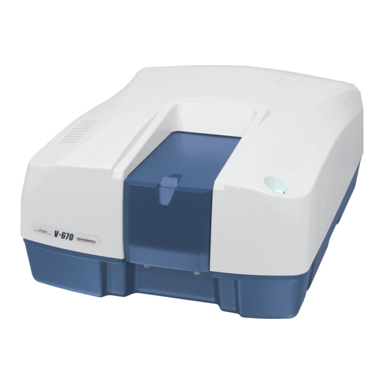
4.2 V-650/660/670 Spectrophotometers: Overview 4.2.1 Overview Sample compartment Light source lid "START" switch Fixing screws "Power" switch Figure 4.3 V-650/660/670 appearance Name Function Sample compartment Slide the lid back to open it. The single position cell holder (the standard cell holder) is installed. The cell holder located toward the front is the sample cell holder, and the one located toward the rear is the reference cell holder.
4.2.2 Rear Panel "GND" " RECORDER " " AUX" " iRM " " USB " Fuse Warning indications "AC INPUT" Figure 4.4 V-650/660/670 rear panel Name Function AC INPUT The power supply input connector. Connect with the power cable. Fuse Fuses for the main unit.
4.3 Standard Cell Holder (Model USE-753 Rectangular Cell Holder) Reference cell holder Sample cell holder Accessory information Accessory information chip contact Fixing screw holes Figure 4.5 Standard cell holder (Model USE-753 Rectangular cell holder) Name Function Sample cell holder Mount the cell containing the sample here. Reference cell holder Mount the cell containing the reference solvent here.
5 Maintenance Pay attention to the instrument operating environment and always keep it clean so that the instrument can be used in a stabilized condition over a long period. This section contains instructions on how to clean the sample compartment when a sample is spilt, and on replacing consumables.
AC power cable from the outlet before replacing a fuse. V-630 uses 2A time-lag fuses (P/N: 5840-H102A 5pcs/set) when using a 100 V voltage supply and 1.6 A time-lag fuses (P/N: 5840-H106A 5pcs/set) when using a 200 V voltage supply. V- 650/660/670 use 2.5 A time-lag fuses (P/N: 5840-H103A 5pcs/set) when using a 100 V voltage...
Page 38
(4) Plug the power cable into the “AC INPUT” and turn the power switch on, then check that the instrument can be operated. Note: If the fuses burn out again soon after replacement, contact your nearest local JASCO distributor. Fuses Fuse holder...
(1) Slide the outer lid of the light source unit to remove it and then remove the inner lid (Fig. 5.4). The way to remove the lamp is the same for V-630, even though V-650/660/670 is shown in figure 5.4.
(4) Adjust the light source mirror as described in Section 5.3.2.2 or 5.3.2.3. lamp stopper Adjustment screw WI lamp stopper Adjustment screw lamp WI lamp Figure 5.5 Light source unit (V-630) D2 lamp stopper Adjuatment screw WI lamp stopper Adjustment screw lamp WI lamp Figure 5.6 Light source unit (V-650/660/670)
Page 41
(2) Select [Environment] from the main menu to display the [Environment] menu. (3) Select [Single Beam Measurement] from the [Environment] menu to display the single beam measurement window. (4) Set parameters as follows. V-630 measurement parameters V-650/660/670 measurement parameters Photometric mode Photometric mode...
<<Adjustment of light source mirror for halogen lamp>> (1) Turn on the instrument. (2) Start [Abs/%T meter] from the [Spectra Manager] window and appears the [Abs/%T meter] window. (3) Set parameters as follows. V-630 measurement parameters V-650/660/670 measurement parameters Photometric mode Sample Photometric mode...
In the event that the trouble cannot be corrected after following the actions given in the troubleshooting chart, contact your local JASCO distributor and provide the model name and serial number of your instrument together with a complete description of the problem.
Page 45
5.3.1.) If the fuse blows blown. immediately after replacement, the electrical system is faulty. Contact your local JASCO distributor. lamp does Check the WI lamp to see if it has Replace the lamp with a new come on. burnt out.
Page 46
JASCO Corporation 2967-5, Ishikawa-machi, Hachioji-shi TOKYO, JAPAN Printed in Japan...
Need help?
Do you have a question about the V-630 and is the answer not in the manual?
Questions and answers