
Related Manuals for Jasco J-810


Summary of Contents for Jasco J-810
- Page 1 MODEL J-810 SPECTROPOLARIMETER Hardware/Function Manual JASCO Corporation P/N: 0302-0407A March 1999...
- Page 2 Safety Cautions Correct operation and scheduled maintenance are essential for safe use of the instrument. Read the safety cautions in this manual and fully understand them before operation. ″WARNING″, ″CAUTION″ and ″Note″ are used throughout this manual to call operator′s attention to safety. (1) Meanings of safety notations WARNING : Failure to comply with this involves the possibility of death or serious personal injury.
- Page 3 Location of Warning Labels The instrument is labeled with the following warnings. Use care not to damage or tear the labels. Should the labels be stained or torn, contact your local JASCO distributor with its part number. WARNINGS! Handling the Xenon Lamp (①of Fig. 1) Part number:0822-0127A...
- Page 4 Use only fuses of the designated rating to protect both the operator and the ″ equipment from fire and other hazards. When replacing the fuse, turn OFF the ″ Power switch and unplug the power cable from the outlet to avoid electric shock. WARNING! Grounding (③in Fig.
- Page 5 Introduction This manual is intended to serve as a guide for using the Model J-810 spectropolarimeter, both for experienced and first-time operators. Prior to operating the instrument, the operator should carefully read and thoroughly ″ ″ understand the contents of these manuals.
-
Page 6: Table Of Contents
Contents 1. Overview and Specifications ............1 1.1 Overview....................1 1.1.1 Principles of operation ..............1 1.1.2 Optical system .................. 2 1.1.3 Electrical system................3 1.2 Specifications..................4 2. Unpacking and Installation ............7 2.1 Unpacking ....................7 2.2 Installation Requirements ............... 7 2.3 Reassembly .................... -
Page 7: Overview And Specifications
1. Overview and Specifications 1.1 Overview 1.1.1 Principles of operation When linearly-polarized light passes through an optically-active substance, its two circularly-polarized components (right and left circularly-polarized beams of light) travel at different speeds, and are absorbed in differing degrees by the substance. Thus, the light passing through the substance is elliptically polarized, and the substance is said to ″... -
Page 8: Optical System
E by choosing an appropriate value for G, [ ] can be determined with a high degree of accuracy. 1.1.2 Optical system Fig. 1.1 shows the optical system of the Model J-810 spectropolarimeter. M S M 1... -
Page 9: Electrical System
A xenon lamp is used as the light source. The light emitted from the xenon lamp is converged by the M mirror into the S entrance slit. The optical system between the entrance slit and the S intermediate slit is referred to as the first monochromator, and the optical system between the S intermediate slit and the S exit slit is referred to... -
Page 10: Specifications
The DC component is separated between the preamplifier and the CD amplifier, and is compared with the reference voltage in order to control the voltage of the PM power supply. This voltage is also applied to the PM detector, changing the PM sensitivity. The AC component is converted to a digital signal after being amplified by the preamplifier and the CD amplifier. - Page 11 ± 0.8 nm at 500 to 800 nm ± 2.0 nm at 800 to 1100 nm ± Wavelength repeatability : 0.05 nm at 163 to 250 nm ± 0.1 nm at 250 to 500 nm ± 0.2 nm at 500 to 1100 nm Spectral bandwidth : 0.01 to 15 nm µ...
- Page 12 Main unit (large sample chamber) : × × 1270mm wide 570mm deep 410mm high Weight : Main unit (small sample chamber): 87 kg Main unit (large sample chamber): 106 kg Power requirements : 100, 115, 200, 220, 230, 240 V, 50/60 Hz 270 W (150 W light source) 670 W (450 W light source)
-
Page 13: Unpacking And Installation
Note: Hold the monochromater bench when you move the main unit. 2.1 Unpacking After unpacking the instrument, check the parts received against the list of components (Table 2.1). If any part is missing or damaged, contact your local JASCO distributor. Table 2.1 List of Components for J-810 Spectropolarimeter Component ′... -
Page 14: Reassembly
. Nitrogen gas tube : 3 m in length, inside diameter : 9.5 mm. 2.3 Reassembly Note: Reassembly of the instrument is performed by your local JASCO distributor. 2.3.1 Removing the cushion from the main unit CAUTION : When removing the cushion, be careful not to give an impact to the cam. -
Page 15: Installing The Modulation Element
2.3.2 Installing the modulation element The modulation element has been removed from the main unit before shipment to prevent damage in transit. Install the modulator element in the main unit after installing the main unit. Remove the electrical system cover from the main unit. Electrical system cover Pull Setscrews... -
Page 16: Installation The Detector Unit
Solder Modulator element Lead wire Holder Fig. 2.5 Mounting the modulator element 2.3.3 Installation the detector unit CAUTION : Handle the detector unit with great care. Do not give an impact to the detector unit. CAUTION : Do not loosen any screws, except for the lock screw. CAUTION : Do not expose the detector window to intense light. -
Page 17: Connecting The Cables And Tubes
2.3.4 Connecting the cables and tubes Connect the cables and tubes according to the following procedure : Connecting the cables Using a digital voltmeter, confirm that the supplied line voltage corresponds to the voltage shown on the rating plate. CAUTION : The line voltage must be confirmed. An outlet can provide an incorrect voltage due to faulty wiring. - Page 18 Water outlet Water inlet Cooling water tube Fig. 2.8 ″ ″ Connect the Water Inlet of the light source cooling water flow sensor to the faucet using the tube. ″ ″ 2) Connect the Water Outlet of the light source cooling water flow sensor to the ″...
- Page 19 Fig. 2.9...
-
Page 20: Names Of Functions Of Components
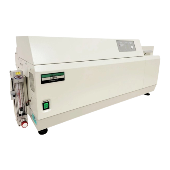
3. Names of Functions of Components 3.1 Overall View 150W light source. Small sample chamber Fig. 3.1 Overall view (150 kW light source. Small sample chamber) - Page 21 450W light source. Large sample chamber Fig. 3.2 Overall view (450kW light source. Large sample chamber)
- Page 22 Component Function ″ ″ Power switch of the main unit. Power switch ① Set sample. ②Sample chamber Inlet and outlet ports of constant temperature water. ③Constant temperature water ports Houses the photomultiplier tube and preamplifier. ④Detector unit Houses the amplifier and other elements. ⑤Amplifier unit Outlet for the water leaking from sample chamber.
-
Page 23: Panels
3.2 Panels Alarm Lamp Shutter Open Temperature (Lamp) Water Flow (Lamp) Water Leak (Sample Chamber) N2 Flow Fig. 3.3 Front panel of amplifier unit Component Function ″ ″ Lights if the light source temperature becomes Temperature (Lamp) ① abnormally high. The light source is automatically turned off if an alarm is displayed. - Page 24 Accessory CD In ORD In PS In Scale Correction ORD Unit LD ORD Offset Scale Correction ×1 ×100 Optical unit I/O 1 I/O 2 Serial Fig. 3.4 Rear panel of amplifier unit Component Function ″ ″ Connect to the connector on the detector unit. CD In connector ①...
- Page 25 T10A T6.3A Amp Unit T3.15A PS Out AC INPUT Fig. 3.5 Rear panel of monochromator unit Component Function ″ ″ ″ ″ Amp Unit connector Connect to the Optical In connector on the rear panel ① of the amplifier unit. ″...
-
Page 26: Sample Chamber
3.3 Sample Chamber Small sample chamber Large sample chamber Fig. 3.6 Sample chamber... - Page 27 Component Function Set the cell. ①Cell holder Set the cell holder. ②Cell holder mount Remove this when a medium-sized accessory like ③Sample stage sub-base (1) Peltier type thermostatted cell holder is mounted. Remove this when a small-sized accessory like ④Sample stage sub-base (2) sample changer is mounted.
-
Page 28: Detector Unit
3.4 Detector Unit Fig. 3.7 Detector unit Component Function Secures the detector unit to the main unit. ①Lock screw ″ ″ ②Connector Connect to the CD In connector located on the rear panel of the amplifier unit. Indicates the wavelength range. Install the detector ③Label unit on the main unit with this label facing upward. -
Page 29: Maintenance
4. MAINTENANCE 4.1 Light Source Check and Replacement The service life of the xenon lamp is 300 to 500 hours, but it differs considerably from one light source to another. It is therefore difficult to predict life expectancy from operating hours. It is generally predicted from noise on the measured data. Compare the current data with the data on delivery (data obtained with a new light source) to make decision. - Page 30 (150W Light source) Light source cover Anode holder Light source Cathode adaptor M mirror M mirror (450W Light source) Anode holder Light source M mirror M mirror Cathode fixing screw Fig. 4.1 Tighten the cathode fixing screw (for the 450W light source) Mount the anode holder (for the 450W light source).
-
Page 31: Energy Check
Fig. 4.2 Setting parameters (replacement of light source) (10) Select the [Move Wavelength...] command from the [Setting] menu and set the ″ ″ wavelength at 546.1 nm Fig. 4.3 Setting wavelength (replacement of light source) (11) Remove the cover from the M and M mirrors. - Page 32 shorter wavelength region (250 nm and less). Check the energy about once a year. The M and M mirrors should be replaced every two years, and the M through M mirrors should be replaced every five years. Note : If an energy decrease is observed in the long wavelength region, improper optical alignment or a other trouble is suspected.
-
Page 33: Wavelength Accuracy Check And Adjustment
4.3 Wavelength Accuracy Check and Adjustment Note : Before checking wavelength accuracy, warm up the instrument for about one hour after turning the light source ON. Note : Use neodymium glass as the sample. <Procedure> Start up the Spectrum Measurement program. Select the [Parameter...] command from the [Measurement] menu, and designate the measurement parameters shown in Fig. -
Page 34: Cd Scale Check And Adjustment
wavelength lever will be visible from below, as shown in Fig. 4.10. If the main unit is mounted on a table or bench, bridge the instrument across two tables or benches to permit access to the adjustment screws. Coarse adjustment screw Fine adjustment screw Wavelength lever Fig. - Page 35 Fig. 4.11 Measurement parameters (CD scale check) Fill the 10mm light path cell with 0.06% aqueous solution of ammonium d-10- camphor sulfonate (solvent : distilled water), and mount the cell in the sample chamber. Select the [Start] command from the [Measurement] menu to make measurement. Using the spectrum analysis program, confirm that the peak value of Channel 1 ±...
-
Page 36: Test Signal Check
Fig. 4.13 Setting wavelength (CD scale adjustment) ″ ″ Turn the Scale Correction CD knob located on the rear panel of the amplifier unit (Fig. 3.4) until the CD value comes within the reference range. Measure the CD spectrum to check the CD scale. 4.5 Test Signal Check The test signal is used to check if the electrical system is operating normally. -
Page 37: Troubleshooting
The following table describes basic corrective actions for specific symptoms. If the difficulty cannot be corrected by performing these actions, failure of the instrument is suspected. In this case, contact your local JASCO distributor with detailed information about your difficulty, including the model name, serial number, and date of manufacture of your instrument. - Page 38 Is the wavelength set to a Set the wavelength to a value at which the detector is value at which the detector not sensitive? is sensitive. Is the nitrogen gas flow rate Increase the nitrogen gas high enough when flow rate. wavelength is set below 180 Is the ″HT″...
- Page 39 Is the sample deteriorated by Use the shutter function or the light emitted from the light narrow spectrum source? bandwidth. Is the variation of the peak Normal. value of aqueous solution of ammonium d-10-camphor sulfonate (distilled water, 10 nm cell) at 291.0 nm within 2 mdeg/hr? Are room temperature and Maintain room temperature...
Need help?
Do you have a question about the J-810 and is the answer not in the manual?
Questions and answers