Table of Contents
Advertisement
Quick Links
Advertisement
Table of Contents

Subscribe to Our Youtube Channel
Related Manuals for iSystem IC57163


Summary of Contents for iSystem IC57163
- Page 1 Infineon DAP Active Probe V1.9 User Manual...
- Page 2 This document and all documents accompanying it are copyrighted by iSYSTEM AG and all rights are reserved. Duplication of these documents is allowed for personal use. In all other cases, written consent from iSYSTEM is required. Copyright iSYSTEM AG.
-
Page 3: Table Of Contents
Contents Introduction ..........................1 Important safety notice ....................... 2 Package content .......................... 3 Specifications ..........................4 Operation............................. 5 Device overview ........................5 Device description ........................5 Recommended Target Debug Connectors and Position ............6 ECU14 DAP 10-pin 1.27mm Adapter ................... 7 Active Probe and the iC5700 Connecting Guidelines ............... -
Page 4: Introduction
Scripts can also be executed directly from within winIDEA, thereby allowing the developer to extend its functionality. iSYSTEM's solutions run under the Microsoft® Windows® operating system or optionally within the Eclipse environment through a plug-in. All our software can be downloaded from the... -
Page 5: Important Safety Notice
Use this instrument only for its intended purpose as specified by this manual to prevent potential hazards. Use included power cord and power supply The enclosed power supply has been approved for use by iSYSTEM. Please contact iSYSTEM if you need to consider an alternative power. Use grounding wire Prior to applying power to either the BlueBox or the target, connect the device and the target system together with the included grounding wire. -
Page 6: Package Content
Package content The standard Infineon DAP Active Probe kit (ordering code IC57163) is delivered with the following components: Infineon DAP Set of two 10-pin 1.27mm 10 1m FNET Micro Cable Active Probe cm long ribbon cables Ordering code: Ordering code: BB-... -
Page 7: Specifications
MECHANICAL Size 80 x 55 x 18 mm Weight 0.125 kg OPERATION Communication interface to Blue Box iSYSTEM proprietary FNET Debug signal valid input voltage range 3.3V (max. 3.6V) Power consumption Max. 1.5W (dependent on operation mode) PROTECTION Debug signals 33Ω... -
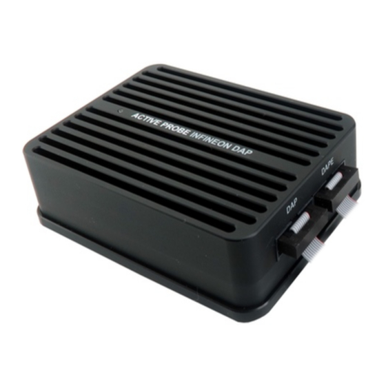
Page 8: Operation
Operation Device overview Device description The front side features: • A – 10-pin DAP connector, with the following pinout: Signal Signal Signal Signal Signal Signal Direction Description description Direction Reference VREF DAP1 DAP data pin IN/OUT Voltage Ground DAP0 DAP clock Optional Ground DAP2... -
Page 9: Recommended Target Debug Connectors And Position
Use only original iSYSTEM accessories for powering and connecting with the iC5700. Consult with iSYSTEM before attempting to use any other accessory. Recommended Target Debug Connectors and Position The target debug connector is a 10-pin, 1.27mm, double-row connector, typically a Samtec... -
Page 10: Ecu14 Dap 10-Pin 1.27Mm Adapter
ECU14 DAP 10-pin 1.27mm Adapter If your target features ECU14 DAP 10-pin 1.27mm connector (defined by Bosch) instead of 10-pin 1.27 mm Infineon DAP connector, use iSYSTEM ECU14 DAP 10-pin 1.27mm Adapter, which acts as a pinout converter. The adapter must be ordered separately under the IADAP10ECU14 ordering code. -
Page 11: Setting Debug Interface Voltage Levels
Although it looks similar to the HDMI interface, the FNET Port is not compatible with HDMI or any HDMI accessories. Connecting iSYSTEM hardware to HDMI accessories will damage the hardware and will render the iSYSTEM hardware warranty void. • The Active Probe can be connected to the target in two configurations. -
Page 12: Further Active Probe Settings
When the VREF signal (pin 1) is 3.3V or less, the debug interface logic should be supplied by the Active Probe (right radio-button selected as shown above), with an appropriate voltage selected from the drop-down list options. When the microcontroller target supplies 5.0V to the VREF signal (pin 1), use the radio-button selection to choose the ‘Vref’... - Page 13 debug channel mode is configured as “DAP” by default. The DAP frequency set must be configured in the field to the right of the drop-down lists, with the frequency being entered in kHz. When the DAPE interface is not in use, ensure the 'DAPE' checkbox remains unchecked. For simultaneous DAP and DAPE operation, the 'DAPE' checkbox should be checked.
-
Page 14: Accessories
IOM6-HUB with three extra FNET ports & FBridge IC57040 CAN/LIN Add-On Module IC57041 Analog/Digital Input/Output Add-On Module IC57125 ARM HSSTP Active Probe IC57163 Infineon DAP Active Probe IC57164 Infineon AGBT Active probe Infineon DAP Active Probe Accessories Ordering Code Description IA10PIN10PIN127-AP Set of two 10-pin, 1.27mm, 10cm long DAP interface ribbon cables... -
Page 15: Technical Support
Technical support To reach for technical support please visit www.isystem.com/support. - Page 16 Whilst iSYSTEM reserves the right to make changes to its products and/or the specifications detailed herein, it does not make any representations or commitments to update this document.
Need help?
Do you have a question about the IC57163 and is the answer not in the manual?
Questions and answers