Table of Contents
Advertisement
Quick Links
Advertisement
Table of Contents

Related Manuals for iSystem IC57164


Summary of Contents for iSystem IC57164
- Page 1 Infineon AGBT Active Probe V1.7 User Manual...
- Page 2 This document and all documents accompanying it are copyrighted by iSYSTEM AG and all rights are reserved. Duplication of these documents is allowed for personal use. In all other cases, written consent from iSYSTEM is required. Copyright © iSYSTEM AG.
-
Page 3: Table Of Contents
Contents Introduction ..........................4 Important safety notice .......................5 Package content ..........................6 Specifications ..........................7 Operation .............................8 Device overview ........................8 Device description ........................8 Target connector ........................9 10-pin 1.27 mm DAP Adapter ....................9 Active Probe and the iC5700 Connecting Guidelines ..............11 Setting Debug Interface Voltage Levels ..................11 Further Active Probe Settings .....................12 Lane link speed ........................14 Accessories ..........................15... -
Page 4: Introduction
This is where our Software Development Kit (SDK) isystem.connect comes in. The well documented interface provides access to Python, Java, C++ and other languages so that any action available within winIDEA and testIDEA can be scripted. -
Page 5: Important Safety Notice
Use this instrument only for its intended purpose as specified by this manual to prevent potential hazards. Use included power cord and power supply The enclosed power supply has been approved for use by iSYSTEM. Please contact iSYSTEM if you need to consider an alternative power. Use grounding wire Prior to applying power to either the BlueBox or the target, connect the device and the target system together with the included grounding wire. -
Page 6: Package Content
1 m FNET Cable User manual Ordering code: IC57164 Ordering code: BB-FNET-100 The Infineon AGBT Active Probe kit (ordering code IC57164-62) can be delivered with longer cable, i.e. 62 cm in length. Infineon AGBT Active Probe 1 m FNET Cable... -
Page 7: Specifications
Size 80 x 55 x 18 mm Weight 0.125 kg OPERATION Communication interface to BlueBox iSYSTEM proprietary FNet Debug signal valid input voltage range 3.3V (max. 3.6V) Power consumption Max. 3W (dependent on operation mode) Number of supported AGBT lanes... -
Page 8: Operation
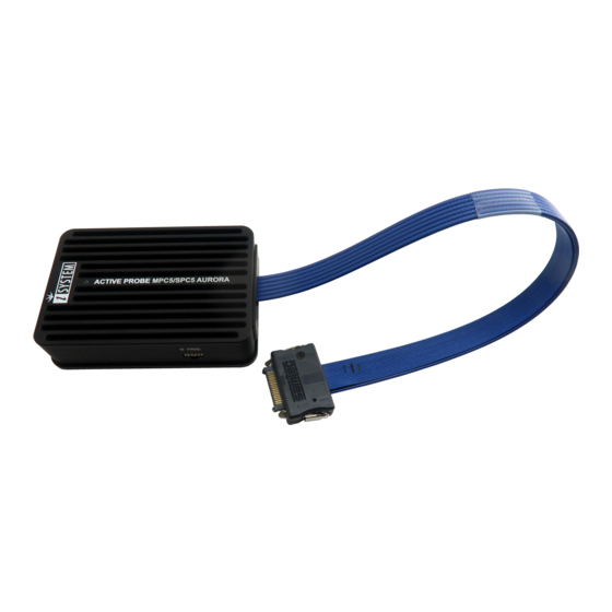
Operation Device overview Device description • A – Samtec 22-pin ERF8 connector, with the following pinout: Signal Signal Signal Signal Signal Signal Direction Description description Direction AGBT TX0_P TX0+ VREF Reference Voltage AGBT TX0_N TX0- DAP0 DAP clock Ground DAP1 DAP data AGBT TX1_P*... -
Page 9: Target Connector
Use only original iSYSTEM accessories for powering and connecting with the iC5700. Consult with iSYSTEM before attempting to use any other accessory. Target connector The target should feature a matching part, for example, Samtec part number: ASP-137969-01 (Samtec Series ERF8, Rugged High-Speed Socket). - Page 10 If the 10-pin 1.27 mm pitch ribbon cable gets damaged, it can be ordered as a spare part under the ordering code IA10PIN10PIN127. Detached 10-pin 1.27mm pitch ribbon cable...
-
Page 11: Active Probe And The Ic5700 Connecting Guidelines
If a cable longer than 1.0m is required (for example when debugging an ECU in a vehicle or a confined space), optional 3m and 5m FNET cables are available from iSYSTEM. Although it looks similar to the HDMI interface, the FNET Port is not compatible with HDMI or any HDMI accessories. -
Page 12: Further Active Probe Settings
When the VREF signal (pin 1) is 3.3V or less, the debug interface logic should be supplied by the Active Probe (right radio-button selected as shown above), with an appropriate voltage selected from the drop-down list options. When the microcontroller target supplies 5.0V to the VREF signal (pin 1), use the radio-button to select the Vref option instead. - Page 13 In the Hardware menu / Emulation Options dialog / Probe tab the Active Probe option must be selected. Click Refresh and select the displayed AP Infineon AGBT. If you have several Active Probes connected to your BlueBox, select the desired Active Probe from the drop-down menu. If you have only one Active Probe connected, you can leave the Active Probe selection box empty and winIDEA will automatically connect to an available Active Probe...
-
Page 14: Lane Link Speed
Lane link speed Default the lowest Aurora link speed is set which ensures the most likely working trace operation. Note that this setting directly impacts on Aurora trace interface bandwidth. The higher the speed, more trace information per time unit can be broadcasted over the interface. Hence, once the Analyzer trace operation (e.g. -
Page 15: Accessories
IC57040 CAN/LIN Add-On Module IC57041 Analog/Digital Input/Output Add-On Module IC57125-1 ARM HSSTP II Active Probe IC57163 Infineon DAP/DAPE Active Probe IC57164 Infineon AGBT Active Probe IC57150 MPC5x/SPC5x Aurora Active Probe Infineon AGBT Active Probe Accessories Ordering Code Description IASAM22TRICOREPIN10 10-pin 1.27 mm DAP Adapter BB-FNET-100 1.0m FNet Cable... - Page 16 Whilst iSYSTEM reserves the right to make changes to its products and/or the specifications detailed herein, it does not make any representations or commitments to update this document.
Need help?
Do you have a question about the IC57164 and is the answer not in the manual?
Questions and answers