Table of Contents
Advertisement
Quick Links
Advertisement
Table of Contents

Subscribe to Our Youtube Channel
Related Manuals for iSystem C6000 BlueBox


Summary of Contents for iSystem C6000 BlueBox
- Page 1 iC6000 BlueBox On-Chip Analyzer V2.2 User Manual...
- Page 2 This document and all documents accompanying it are copyrighted by iSYSTEM AG and all rights are reserved. Duplication of these documents is allowed for personal use. In all other cases, written consent from iSYSTEM is required. iSYSTEM AG. All rights reserved.
-
Page 3: Table Of Contents
Contents iC6000 BlueBox Important safety notice ......................... 5 Package content ............................6 Specifications ............................7 Operation ..............................8 Device description ..........................................9 Connecting the iC6000 to the Target ................................. 11 Aurora DTM module ........................................12 High-Speed Aurora cable ......................................14 Aurora Interface Board Layout Guidelines .............................. -
Page 4: Ic6000 Bluebox
More information isystem.com/sdk. iSYSTEM's solutions run under the Microsoft® Windows® operating system or optionally within the Eclipse environment through a plug-in. All our software can be downloaded from the Downloads page at http://www.isystem.com. -
Page 5: Important Safety Notice
Use included power cord and power supply - The enclosed power supply has been approved for use by iSYSTEM. Please contact iSYSTEM if you need to consider an alternative power. Use grounding wire - Prior to applying power to either the BlueBox or the target, connect the device and the target system together with the included grounding wire. -
Page 6: Package Content
Package content The standard iC5700 order is delivered with the following components: iC6000 Base Unit including the preassembled Power supply USB 3.0 cable Aurora DTM and Aurora Cable IC60000-1 + IC6002x-1 + IC6004x-1 Ordering code: Ordering code: IC30000-PS BB-USB30-180 Ethernet cable Grounding wire User Manual Ordering code:... -
Page 7: Specifications
Specifications GENERAL Operating temperature 10°C to 40°C Storage temperature -10°C to 60°C Humidity 5% to 80% RH MECHANICAL Size 155 x 155 x 65 mm Weight approx. 800g OPERATION Communication USB 2.0, USB 3.0, 10/100 Ethernet interfaces to PC Supply voltage 10V to 24V DC Power consumption <... -
Page 8: Operation
Operation Device overview... -
Page 9: Device Description
Device description The top face of the iC6000 features: A – The indicator lights provide the status of the iC6000 hardware as follows. Power Indicator – Green R - Running indicator – Red F - Free indicator – Yellow On – Powered on On –... - Page 10 Target. When powering down the system, power off the Target before powering off the BlueBox unit! FBridge port is not Ethernet port! Use only original iSYSTEM accessories for powering and connecting with the BlueBox unit. Consult with iSYSTEM before attempting to use any other accessory.
-
Page 11: Connecting The Ic6000 To The Target
Grounding wire Always start by connecting the iC6000 to the target hardware with the enclosed grounding wire. Refer to winIDEA Help www.isystem.com/groundingwire for more information. If the grounding wire is not connected, the ground potential difference between the BlueBox hardware and the target can exceed well over 1000V even before any of the devices are powered up. -
Page 12: Aurora Dtm Module
If a later Aurora DTM module exchange is required, for example to connect the iC6000 to the microcontroller architecture supported by different Aurora DTM module, the exchange has to be carried out by iSYSTEM. Next table shows which Aurora DTM module is required for the specific debug interface and... - Page 13 The following Aurora DTM modules are available: iC6000 DTM Aurora/JTAG (MPC57xx, SPC57, Aurix) Ordering code IC60022-1 iC6000 DTM Aurora/DAP (Aurix) Ordering code IC60023-1 Both, 2-pin and 3-pin (Wide Mode) DAP debug interfaces are supported. The DAP interface width is configurable in winIDEA. iC6000 DTM Aurora/LPD (RH850) Ordering code IC60024-1...
-
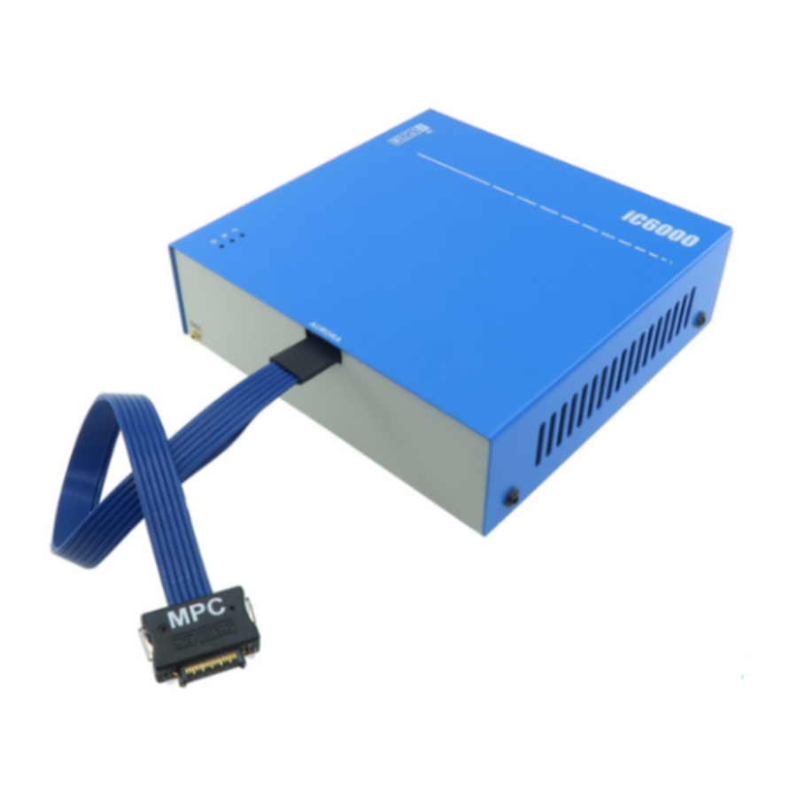
Page 14: High-Speed Aurora Cable
High-Speed Aurora cable The iC6000 comes preassembled with one of the available High-Speed Aurora cables supporting different microcontroller architectures. The target microcontroller architecture and the debug interface type must be specified when ordering the iC6000. Based on this information, the according Aurora DTM module and High- Speed Aurora cable are mounted and delivered with the iC6000 order. - Page 15 The following pinout is valid on the target side: Signal Signal Signal Signal Signal Signal Direction Description Description Direction Reference AGBT TX0_P TX0+ Vref Voltage JTAG / DAP AGBT TX0_N TX0- TCK / DAP0 O / O Clock JTAG / DAP Ground TMS / DAP1 O / IO...
- Page 16 Note that the optional length should be reasonable (e.g. 10 cm) since the quality of electrical signals degrades with prolonging the cable. iSYSTEM gives no assurance for BlueBox operation with this cable. The cable is meant to be used only for boundary cases where BlueBox cannot be connected to the target hardware through the standard debug adapter, for example due to the physical obstacles of the target system.
- Page 17 16-pin 2.54 mm JTAG Adapter Ordering code IASAM22TRICOREPIN16 This adapter must be ordered separately to connect to the target featuring 16-pin 2.54mm pitch JTAG target debug connector. The adapter can be used only in conjunction with the iC6000 DTM Aurora/JTAG module (IC60022-1). The following pinout is valid on the target side: Signal Signal...
- Page 18 Signal Signal Signal Signal Signal Signal Direction Description Description Direction Reference AGBT TX0_P TX0+ Vref Voltage AGBT TX0_N TX0- JTAG Ground JTAG AGBT TX_P1 JTAG AGBT TX_N1 JTAG JTAG TRST Ground JCOMP (optional) AGBT TX_P2 Not Connected Nexus Event AGBT TX_N2 EVTI0 O (not used) Input...
- Page 19 Ordering code IASAM34MPCPIN14 If your target features 14-pin 2.54mm pitch JTAG target debug connector, use iSYSTEM 14-pin 2.54 mm JTAG Adapter which acts as a pinout converter. The adapter must be ordered separately. The adapter can be used only in conjunction with the iC6000 DTM Aurora/JTAG module (IC60022-1).
- Page 20 34-pin High-speed Aurora cable for Renesas RH850 Ordering code IC60042-1 This cable is delivered under the IC60042-1 ordering code and is required to connect the iC6000 to Renesas RH850/P1H-C based target providing Samtec 34-pin ERF8 debug connector. Target connector and the placement The target should feature a matching part, for example, Samtec part number: ASP-137973-01 (Samtec Series ERF8, Rugged High Speed Socket).
- Page 21 The iC6000 unit can be used to connect to these targets through a small adapter connecting at the end of the 34-pin High-speed Aurora cable.
- Page 22 14-pin 2.54 mm LPD Adapter Ordering code IASAM34RH850PIN14 An adapter must be ordered separately to connect to the target featuring 14-pin 2.54mm pitch LPD target debug connector. This adapter can be used only in conjunction with the iC6000 DTM Aurora/LPD module (IC60024-1). The following pinout is valid on the target side: Signal Signal...
-
Page 23: Aurora Interface Board Layout Guidelines
Aurora Interface Board Layout Guidelines Aurora interface runs at speeds up to 5Gbps, which means high-speed board layout guidelines and practice must be considered while routing Aurora physical interface from the transmitter to the receiver. On the iC6000 side the Aurora interface lines are connected directly to the FPGA implementing the physical Aurora interface. -
Page 24: Accessories
34-pin High-speed Aurora cable for NXP MPC57xx and ST SPC57 IC60042-1 34-pin High-speed Aurora cable for Renesas RH850 Power supplies and cables Ensure proper operation of your iC6000 operation by using approved iSYSTEM power supplies and cables. Ordering code Description... -
Page 25: Declarations
· Signed for and on behalf of: Schwabhausen, 21. March 2017 iSYSTEM AG f. Informatiksysteme - Carl-Zeiss-Str. 1 - 85247 Schwabhausen - USt-IdNr. DE128231221 Vorstand: Erol Simsek, Werner Fischer, Martin Gröstenberger - AG: München HRB 148751 - St-Nr.: 115/120/30027 Bank: Sparkasse Dachau BLZ 70051540 Account 904045 - IBAN: DE82700515400000904045 - BIC:... -
Page 26: User Notes
User Notes This page is intentionally left blank. -
Page 27: User Notes
User Notes This page is intentionally left blank. - Page 28 Whilst iSYSTEM reserves the right to make changes to its products and/or the specifications detailed herein, it does not make any representations or commitments to update this document.
Need help?
Do you have a question about the C6000 BlueBox and is the answer not in the manual?
Questions and answers