Table of Contents
Advertisement
Quick Links
Advertisement
Table of Contents

Subscribe to Our Youtube Channel
Related Manuals for iSystem Infineon AGBT


Summary of Contents for iSystem Infineon AGBT
- Page 1 Infineon AGBT Active Probe V1.8 User Manual Enabling Safer Embedded Systems...
- Page 2 This document and all documents accompanying it are copyrighted by iSYSTEM AG and all rights are reserved. Duplication of these documents is allowed for personal use. In all other cases, written consent from iSYSTEM is required. iSYSTEM AG. All rights reserved.
-
Page 3: Table Of Contents
Contents Infineon AGBT Active Probe Important safety notice ......................... 5 Package content ............................6 Specifications ............................7 Operation ..............................8 10-pin 1.27 mm DAP Adapter ....................................10 Active Probe and the iC5700 Connecting Guidelines ..............11 Setting Debug Interface Voltage Levels ................................. 12 Further Active Probe Settings ...................... -
Page 4: Infineon Agbt Active Probe
More information isystem.com/sdk. iSYSTEM's solutions run under the Microsoft® Windows® operating system or optionally within the Eclipse environment through a plug-in. All our software can be downloaded from the Downloads page at http://www.isystem.com. -
Page 5: Important Safety Notice
Use included power cord and power supply - The enclosed power supply has been approved for use by iSYSTEM. Please contact iSYSTEM if you need to consider an alternative power. Use grounding wire - Prior to applying power to either the BlueBox or the target, connect the device and the target system together with the included grounding wire. -
Page 6: Package Content
User Manual Active Probe Ordering code: Ordering code: IC57164 BB-FNET-100 The Infineon AGBT Active Probe kit (Ordering code IC57164-62) can be delivered with longer cable, i.e. 62 cm in length. Infineon AGBT USB-C 1m FNet Cable User Manual Active Probe... -
Page 7: Specifications
5% to 80% RH MECHANICAL Size 80 x 55 x 18 mm Weight 0.125 kg OPERATION Communication iSYSTEM proprietary FNet interface to BlueBox Debug signal valid 3.3V (max. 3.6V) input voltage range Power consumption Max. 3W (dependent on operation mode) Number of supported... -
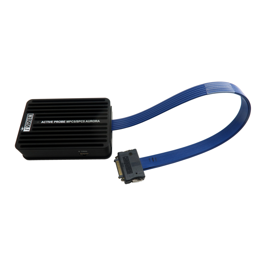
Page 8: Operation
Operation Device overview Device description A – Samtec 22-pin ERF8 connector, with the following pinout: Signal Signal Signal Signal Signal Signal Direction Description Description Direction Reference AGBT TX0_P TX0+ Vref Voltage AGBT TX0_N TX0- DAP0 DAP Clock Ground DAP1 DAP Data AGBT TX1_P* TX1+ Not Connected... - Page 9 When powering down the system, power off the target before powering off the iC5700! FBridge port is not Ethernet port! Use only original iSYSTEM accessories for powering and connecting with the iC5700. Consult with iSYSTEM before attempting to use any other accessory. Target connector The target should feature a matching part, for example, Samtec part number: ASP-137969-01 (Samtec Series ERF8, Rugged High-Speed Socket).
-
Page 10: 10-Pin 1.27 Mm Dap Adapter
Note that the optional length should be reasonable (e.g. 10 cm) since the quality of electrical signals degrades with prolonging the cable. iSYSTEM gives no assurance for BlueBox operation with this cable. The cable is meant to be used only for boundary cases where BlueBox cannot be connected to the target hardware through the standard debug adapter, for example due to the physical obstacles of the target system. -
Page 11: Active Probe And The Ic5700 Connecting Guidelines
If a cable longer than 1.0m is required (for example when debugging an ECU in a vehicle or a confined space), optional 3.0m and 5.0m FNet Micro cables are available from iSYSTEM. Although it looks similar to the HDMI interface, the FNet Port is not compatible with HDMI or any HDMI accessories. -
Page 12: Setting Debug Interface Voltage Levels
Setting Debug Interface Voltage Levels The voltage levels for the debug interface are configured within winIDEA via Hardware menu / CPU Options / Hardware. When the microcontroller target supplies 5.0V to the Vref signal (pin 1), use the radio-button selection to select the Vref option instead. -
Page 13: Further Active Probe Settings
AGBT interface. Alternatively, JTAG debug interface support is also available through a dedicated JTAG cable adapter (e.g. IC50160). Infineon DAP/DAPE Active Probe supporting the DAP and DAPE debug interface · Infineon AGBT Active Probe · Infineon USB-C Active Probe ·... -
Page 14: Lane Link Speed
Lane link speed By default the lowest Aurora link speed is set which ensures the most likely working trace operation. Note that this setting directly impacts on Aurora trace interface bandwidth. The higher the speed, more trace information per time unit can be broadcasted over the interface. Hence, once the Analyzer trace operation (e.g. -
Page 15: Accessories
ARM HSSTP II Active Probe IC57163 Infineon DAP/DAPE Active Probe IC57164 Infineon AGBT Active Probe IC57150 MPC5x/SPC5x Aurora Active Probe Infineon AGBT USB-C Active Probe Accessories Ordering Code Description IASAM22TRICOREPIN 10-pin 1.27 mm DAP Adapter 10-1 BB-FNET-100 1.0m FNet Cable BB-FNET-300 3.0m FNet Cable... - Page 16 Whilst iSYSTEM reserves the right to make changes to its products and/or the specifications detailed herein, it does not make any representations or commitments to update this document.
Need help?
Do you have a question about the Infineon AGBT and is the answer not in the manual?
Questions and answers