Table of Contents
Advertisement
Quick Links
Advertisement
Table of Contents

Related Manuals for iSystem Infineon SGBT


Summary of Contents for iSystem Infineon SGBT
- Page 1 Infineon SGBT (HSTCU) Active Probe V1.5 User Manual...
- Page 2 This document and all documents accompanying it are copyrighted by iSYSTEM AG and all rights are reserved. Duplication of these documents is allowed for personal use. In all other cases, written consent from iSYSTEM is required. iSYSTEM AG. All rights reserved.
-
Page 3: Table Of Contents
Contents Infineon SGBT (HSTCU) Active Probe Important safety notice ......................... 5 Package content ............................6 Specifications ............................7 Operation ..............................8 HSTCU (USB-C) to Samtec22 Converter ................................10 HSTCU (USB-C) to DAP10 1.27 Converter ............................... 12 Active Probe and the iC5700 Connecting Guidelines ..............14 Setting Debug Interface Voltage Levels ................................. -
Page 4: Infineon Sgbt (Hstcu) Active Probe
Scripts can also be executed directly from within winIDEA, thereby allowing the developer to extend its functionality. More information isystem.com/sdk. iSYSTEM's solutions run under Microsoft® Windows®, GNU, Linux OS; or optionally within the Eclipse environment via a plugin. Software can be downloaded from the Downloads page at... -
Page 5: Important Safety Notice
Use included power cord and power supply - The enclosed power supply has been approved for use by iSYSTEM. Please contact iSYSTEM if you need to consider an alternative power. Use grounding wire - Prior to applying power to either the BlueBox or the target, connect the device and the target system together with the included grounding wire. -
Page 6: Package Content
Package content The Infineon Infineon SGBT (HSTCU) Active Probe kit is delivered with the following components: Infineon SGBT (HSTCU) 1m FNet Cable User Manual Active Probe Ordering code: Ordering code: IC57166 BB-FNET-100... -
Page 7: Specifications
5% to 80% RH MECHANICAL Size 80 x 55 x 18 mm Weight 0.125 kg OPERATION Communication iSYSTEM proprietary FNet interface to BlueBox Debug signal valid 3.3V (max. 3.6V) input voltage range Power consumption Max. 1.5W (dependent on operation mode) Number of supported... -
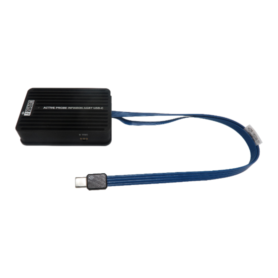
Page 8: Operation
Operation Device overview Device description A – USB-C connector, with the following pinout: Signal Signal Signal Signal Signal Signal Direction Description Description Direction Ground Not Connected AGBT TX0_P TX0+ CLK+ AGBT Clock AGBT TX0_N TX0- CLK- AGBT Clock Not Connected Not Connected Target Reset nRESET... - Page 9 When powering on the system, switch the iC5700 on before powering on the target system. When powering down the system, power off the target before powering off the iC5700! Use only original iSYSTEM accessories for powering and connecting with the iC5700. Consult with iSYSTEM before attempting to use any other accessory.
-
Page 10: Hstcu (Usb-C) To Samtec22 Converter
In general one of the selling points of the USB-C plug is that there is no way to incorrectly insert it. However that is not the case with the Infineon SGBT (HSTCU) Active Probe where used physical USB-C type connector doesn’t feature the USB interface as someone could presume but rather the Infineon AGBT (Aurora GigaBit Trace) interface whose signals are connected to the connector in a way that USB-C connector orientation matters. - Page 11 The following pinout is valid on the converter side: Signal Signal Signal Signal Signal Signal Direction Description Description Direction Ground Not Connected AGBT TX0_P TX0+ CLK+ AGBT Clock AGBT TX0_N TX0- CLK- AGBT Clock Not Connected Not Connected Target Reset nRESET DAP1 DAP Data...
-
Page 12: Hstcu (Usb-C) To Dap10 1.27 Converter
HSTCU (USB-C) to DAP10 1.27 Converter Ordering code IAHSTCU-DAP10 This converter is used to connect Infineon SGBT (HSTCU) Active Probe (Ordering code: IC57166) to the target via DAP connector. When attaching this converter to the Active Probe, make sure its marking A and marking B is aligned and matches with the markings on the Active Probe connector. - Page 13 The following pinout is valid on the target side: Signal Signal Signal Signal Signal Signal Direction Description Description Direction Reference Vref DAP1 DAP Data pin Voltage Ground DAP0 DAP clock Ground DAP2 Optional 2nd DAP Data pin Not Connected DAP3 Optional 3rd DAP Data pin Ground...
-
Page 14: Active Probe And The Ic5700 Connecting Guidelines
If a cable longer than 1.0m is required (for example when debugging an ECU in a vehicle or a confined space), optional 3.0m and 5.0m FNet Micro cables are available from iSYSTEM. Although it looks similar to the HDMI interface, the FNet Port is not compatible with HDMI or any HDMI accessories. -
Page 15: Setting Debug Interface Voltage Levels
Setting Debug Interface Voltage Levels The voltage levels for the debug interface are configured within winIDEA via Hardware menu / CPU Options / Hardware. When the microcontroller target supplies 5.0V to the Vref signal (pin 1), use the radio-button selection to select the Vref option instead. -
Page 16: Further Active Probe Settings
Further Active Probe Settings The iC5700 can connect to AURIX™ target devices through: its installed DTM module and an appropriate DAP cable adapter (e.g. IC50163-2). · This debug system has limited maximum DAP frequency and does not support the DAPE debug interface nor the AGBT interface. - Page 17 3. Click Refresh in Hardware menu / Configure Session / SoC and select the Active Probe. If you have only one Active Probe connected, you can leave the Active Probe selected and · winIDEA will automatically connect to an available Active Probe. If you have several Active Probes connected to your BlueBox, select the desired Active Probe ·...
-
Page 18: Lane Link Speed
Lane link speed By default the lowest Aurora link speed is set which ensures the most likely working trace operation. Note that this setting directly impacts on Aurora trace interface bandwidth. The higher the speed, more trace information per time unit can be broadcasted over the interface. Hence, once the Analyzer trace operation (e.g. -
Page 19: Accessories
IC57163 Infineon DAP/DAPE Active Probe IC57164 Infineon AGBT Active Probe IC57150 MPC5x/SPC5x Aurora Active Probe IC57166 Infineon SGBT (HSTCU) Active Probe Infineon USC-B Active Probe Accessories Ordering Code Description IAHSTCU-SAM22 USB-C to Samtec 22-pin TriCore Adapter BB-FNET-100 1.0m FNet Cable BB-FNET-300 3.0m FNet Cable... - Page 20 Whilst iSYSTEM reserves the right to make changes to its products and/or the specifications detailed herein, it does not make any representations or commitments to update this document.
Need help?
Do you have a question about the Infineon SGBT and is the answer not in the manual?
Questions and answers