Table of Contents
Advertisement
Quick Links
Advertisement
Table of Contents

Related Manuals for iSystem iC5000 CI BlueBox


Summary of Contents for iSystem iC5000 CI BlueBox
- Page 1 CI BlueBox On-Chip Analyzer V1.1 User Manual...
- Page 2 This document and all documents accompanying it are copyrighted by iSYSTEM AG and all rights are reserved. Duplication of these documents is allowed for personal use. In all other cases, written consent from iSYSTEM is required. iSYSTEM AG. All rights reserved.
-
Page 3: Table Of Contents
Contents iC5000 CI BlueBox Important safety notice ......................... 5 Package content ............................6 Specifications ............................7 Operation ..............................8 Device description ..........................................9 Connecting the iC5000 CI to the Target ................................11 Accessories ............................. 14 Declarations ............................16 User Notes .............................. 17 User Notes .............................. -
Page 4: Ic5000 Ci Bluebox
BlueBox technology and their IOM accessories. More information isystem.com/sdk. iSYSTEM's solutions run under the Microsoft® Windows® operating system or optionally within the Eclipse environment through a plugin. All our software can be downloaded from the... -
Page 5: Important Safety Notice
Use included power cord and power supply - The enclosed power supply has been approved for use by iSYSTEM. Please contact iSYSTEM if you need to consider an alternative power. Use grounding wire - Prior to applying power to either the BlueBox or the target, connect the device and the target system together with the included grounding wire. -
Page 6: Package Content
Package content The standard iC5000 order is delivered with the following components: iC5000 CI with pre-assembled DTM 25 cm 40-pin ribbon cable Power supply module Ordering code: Ordering code: Ordering code: IC50000-CI IC50020-25 IC30000-PS USB 2.0 cable Ethernet cable Grounding wire Ordering code: Ordering code: Ordering code:... -
Page 7: Specifications
Specifications GENERAL Operating temperature 10°C to 40°C Storage temperature -10°C to 60°C Humidity 5% to 80% RH MECHANICAL Size 122 x 127 x 45 mm (W x D x H) Weight approx. 500g OPERATION Communication USB 2.0, 10/100 Mbps Ethernet interfaces to PC Supply voltage 10V to 24V DC... -
Page 8: Operation
Operation Device overview... -
Page 9: Device Description
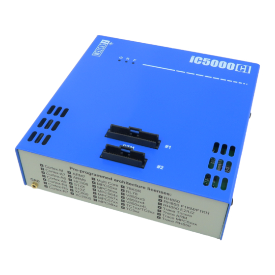
Device description The top face of the iC5000 CI features two key areas; the DTM connectors A and the indicator lights B: A – The Debug Trace Module (DTM) provides two connectors, marked #1 and #2. These connectors are the interface to the target microcontroller. Depending on the target microcontroller debug features, the supplied ribbon-cables will need to be connected to either connector #1 only or connectors #1 and #2. - Page 10 Target. When powering down the system, power off the Target before powering off the BlueBox unit! FBridge port is not Ethernet port! Use only original iSYSTEM accessories for powering and connecting with the BlueBox unit. Consult with iSYSTEM before attempting to use any other accessory. Differences between iC5000 and iC5000 CI...
-
Page 11: Connecting The Ic5000 Ci To The Target
Target. When powering down the system, power off the target before powering off the BlueBox unit! FBridge port is not Ethernet port! Use only original iSYSTEM accessories for powering and connecting with the BlueBox unit. Consult with iSYSTEM before attempting to use any other accessory. - Page 12 Debug Adapter Depending on the Target microcontroller, iSYSTEM supplies one of two different types of connection system to link the BlueBox hardware with the Target microcontroller: Single 40-pin ribbon cable together with a debug adapter suited to the debug connector of ·...
- Page 13 To disconnect the ribbon cable, squeeze the two metal latches on the cable connector inwards and pull the connector gently from the socket. If the delivered ribbon cable does not meet your needs, iSYSTEM offers a range of alternative lengths. Please refer to the Accessories chapter for available ribbon cables.
-
Page 14: Accessories
Accessories Power supplies and cables Ensure proper operation by using approved iSYSTEM power supplies and cables. Ordering Code Description IC30000-PS 19V Power Supply IC30000-PS-CAR12V 12V Car Power Supply BB-PSC-EU Power Supply Cord - EU Plug (type F Plug) BB-PSC-US Power Supply Cord - USA Plug (type B Plug) - Page 15 10-pin 1.27mm Renesas RH850 Debug Adapter IC50177 38-pin Mictor RH850 Nexus 16-bit Debug Adapter Refer to the Debug Adapters User Manual for technical details on the listed debug adapters. Find more information on www.isystem.com or contact sales@isystem.com. To reach for technical support please visit www.isystem.com/support.
-
Page 16: Declarations
· Signed for and on behalf of: Schwabhausen, 21. March 2017 iSYSTEM AG f. Informatiksysteme - Carl-Zeiss-Str. 1 - 85247 Schwabhausen - USt-IdNr. DE128231221 Vorstand: Erol Simsek, Werner Fischer, Martin Gröstenberger - AG: München HRB 148751 - St-Nr.: 115/120/30027 Bank: Sparkasse Dachau BLZ 70051540 Account 904045 - IBAN: DE82700515400000904045 - BIC:... -
Page 17: User Notes
User Notes This page is intentionally left blank. -
Page 18: User Notes
User Notes This page is intentionally left blank. -
Page 19: User Notes
User Notes This page is intentionally left blank. - Page 20 Whilst iSYSTEM reserves the right to make changes to its products and/or the specifications detailed herein, it does not make any representations or commitments to update this document.
Need help?
Do you have a question about the iC5000 CI BlueBox and is the answer not in the manual?
Questions and answers