Table of Contents
Advertisement
Quick Links
Advertisement
Table of Contents

Related Manuals for iSystem IC57163


Summary of Contents for iSystem IC57163
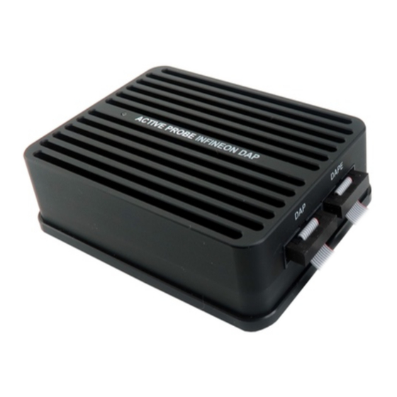
- Page 1 Infineon DAP/DAPE Active Probe V2.7 User Manual...
- Page 2 This document and all documents accompanying it are copyrighted by iSYSTEM AG and all rights are reserved. Duplication of these documents is allowed for personal use. In all other cases, written consent from iSYSTEM is required. iSYSTEM AG. All rights reserved.
-
Page 3: Table Of Contents
Contents Infineon DAP/DAPE Active Probe Important safety notice ......................... 5 Package content ............................6 Specifications ............................7 Operation ..............................8 Device description ..........................................9 Recommended Target Debug Connectors and Position ........................10 ECU14 DAP 10-pin 1.27mm Converter ................................11 MEDC17 DAP 10-pin 1.27mm Converter ................................. 12 ERF8 DAP 22-pin Converter .................................... -
Page 4: Infineon Dap/Dape Active Probe
Scripts can also be executed directly from within winIDEA, thereby allowing the developer to extend its functionality. More information isystem.com/sdk. iSYSTEM's solutions run under the Microsoft® Windows® operating system or optionally within the Eclipse environment through a plugin. All our software can be downloaded from the... -
Page 5: Important Safety Notice
Use included power cord and power supply - The enclosed power supply has been approved for use by iSYSTEM. Please contact iSYSTEM if you need to consider an alternative power. Use grounding wire - Prior to applying power to either the BlueBox or the target, connect the device and the target system together with the included grounding wire. -
Page 6: Package Content
Package content The Infineon DAP/DAPE Active Probe kit is delivered with the following components: Infineon DAP/DAPE Two 10-pin 1.27mm 10cm 1m FNet Active Probe long ribbon cables Micro Cable Ordering code: Ordering code: Ordering code: IC57163 IA10PIN10PIN127-AP BB-FNETMICRO-100 User Manual... -
Page 7: Specifications
5% to 80% RH MECHANICAL Size 80 x 55 x 18 mm Weight 0.125 kg OPERATION Communication iSYSTEM proprietary FNet interface to BlueBox Debug signal valid 3.3V (max. 3.6V) input voltage range Power consumption Max. 1.5W (dependent on operation mode) PROTECTION... -
Page 8: Operation
Operation Device overview... -
Page 9: Device Description
When powering on the system, switch the iC5700 on before powering on the target system. When powering down the system, power off the target before powering off the iC5700! Use only original iSYSTEM accessories for powering and connecting with the iC5700. Consult with iSYSTEM before attempting to use any other accessory. -
Page 10: Recommended Target Debug Connectors And Position
Optionally, a longer ribbon cable can be ordered under the ordering code IA10PIN10P-AP- CUST. The length must be specified at the order. iSYSTEM gives no assurance for BlueBox operation with this cable. The cable is meant to be used only for boundary cases where BlueBox can't be connected to the target hardware through the standard debug adapter, e.g. -
Page 11: Ecu14 Dap 10-Pin 1.27Mm Converter
Infineon DAP/DAPE Active Probe (Ordering code IC57163) acting as a pinout converter is available for TriCore embedded targets featuring the ECU14 10-pin 1.27mm target debug connector. It must be ordered separately. - The following pinout is valid on the target side:... -
Page 12: Medc17 Dap 10-Pin 1.27Mm Converter
Converter is connected at the end of the 10-pin 1.27mm Infineon DAP2 Wide D. Adapter (Ordering code IC50163-2) or Infineon DAP/DAPE Active Probe (Ordering code IC57163) acting as a pinout converter and is available for TriCore embedded targets featuring the MEDC17 10-pin 1.27mm target debug connector. The adapter must be ordered separately. -
Page 13: Erf8 Dap 22-Pin Converter
If your target features a 22-pin Samtec ERF8 target debug connector with the 22-pin ERF8 Aurix target pinout instead of 10-pin 1.27 mm Infineon DAP/DAPE connector, use iSYSTEM ERF8 22-pin Converter, which acts as a pinout converter. The converter must be ordered separately. -
Page 14: Active Probe And The Ic5700 Connecting Guidelines
If a cable longer than 1.0m is required (for example when debugging an ECU in a vehicle or a confined space), optional 3.0m and 5.0m FNet Micro cables are available from iSYSTEM. Although it looks similar to the HDMI interface, the FNet Port is not compatible with HDMI or any HDMI accessories. -
Page 15: Connecting Active Probe To The Target
Connecting Active Probe to the Target The Infineon DAP / DAPE Active Probe can be connected to the Target in two configurations: DAP connector AURIX™ microcontrollers that have only one DAP interface, through which the on-chip debug module and the MCDS trace module can be accessed, should be connected to the Active Probe’s DAP connector and the target microcontroller’s DAP connector. - Page 16 4. (optional) In case of DAPE connector repeat step 2. and 3. with the second cable.
-
Page 17: Setting Debug Interface Voltage Levels
Setting Debug Interface Voltage Levels The voltage levels for the debug interface are configured within winIDEA via Hardware menu / CPU Options / Hardware. When the microcontroller target supplies 5.0V to the Vref signal (pin 1), use the radio-button selection to select the Vref option instead. -
Page 18: Dap And Dape Configuration
DAP and DAPE configuration The Infineon DAP/DAPE Active Probe supports DAP interface operation or simultaneous DAP and DAPE interface operation at maximum DAP/DAPE frequency. Operational modes DAP Standard, a 2-pin DAP with single data line (default) or · DAP Wide, a 3-pin DAP with two data lines ·... -
Page 19: Further Active Probe Settings
Further Active Probe Settings The iC5700 is capable of connecting to AURIX™ target devices through: Its installed DTM module and an appropriate DAP cable adapter, e.g. 10-pin 1.27mm · Infineon DAP2 Wide D. Adapter, ordering code IC50163-2 or This debug system has limited maximum DAP frequency and the DAPE debug port is not supported. - Page 20 3. Click Refresh in Hardware menu / Configure Session / SoC and select the Active Probe. If you have only one Active Probe connected, you can leave the Active Probe selected and · winIDEA will automatically connect to an available Active Probe. If you have several Active Probes connected to your BlueBox, select the desired Active Probe ·...
-
Page 21: Accessories
3.0m FNet Micro Cable (Active Probe) BB-FNETMICRO-500 5.0m FNet Micro Cable (Active Probe) Please refer to the iC5700 BlueBox for all current iC5700 accessories. Find more information on www.isystem.com or contact sales@isystem.com. To reach for technical support please visit www.isystem.com/support. -
Page 22: User Notes
User Notes This page is intentionally left blank. - Page 23 This page is intentionally left blank.
- Page 24 Whilst iSYSTEM reserves the right to make changes to its products and/or the specifications detailed herein, it does not make any representations or commitments to update this document.
Need help?
Do you have a question about the IC57163 and is the answer not in the manual?
Questions and answers