Advertisement
Quick Links
_
V2.4
Hardware Reference
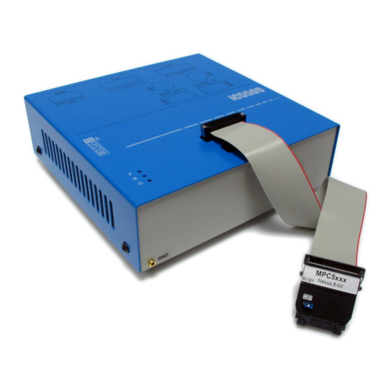
iC5500 On-Chip Analyzer
Thank you for purchasing this product from iSYSTEM. This product has been carefully crafted to satisfy your
needs. Should any questions arise, do not hesitate to contact your local distributor or iSYSTEM directly. Our
technical support personnel will be happy to answer all your technical support questions.
All information, including contact information, is available on our web site www.isystem.com. Feel free also to
explore our alternative products.
iSystem constantly yields for development and therefore certain pictures in this documentation may vary slightly
from the actual product you received. The differences should be minor, but should you find more serious
inconsistencies of the product with the documentation, please contact your local distributor for more
information.
This document and all documents accompanying it are copyrighted by iSYSTEM and all rights are reserved.
Duplication of these documents is allowed for personal use. For every other case a written consent from
iSYSTEM is required.
Copyright 2017 iSYSTEM, AG.
All rights reserved.
All trademarks are property of their respective owners.
www.isystem.com
iSYSTEM, March 2017
1/66
Advertisement

Subscribe to Our Youtube Channel
Related Manuals for iSystem iC5500


Summary of Contents for iSystem iC5500
- Page 1 Hardware Reference iC5500 On-Chip Analyzer Thank you for purchasing this product from iSYSTEM. This product has been carefully crafted to satisfy your needs. Should any questions arise, do not hesitate to contact your local distributor or iSYSTEM directly. Our technical support personnel will be happy to answer all your technical support questions.
- Page 2 Ordering code IC55000 iC5500 Base Unit is a base platform connecting to the PC via the TCP/IP or the USB 3.0 port. The iC5500 USB 3.0 port is backward compatible with the USB 2.0 ports on the PC side. Make sure that the USB 3.0 cable delivered along the iC5500 is being used for the USB 3.0 connection. It has been confirmed that many USB 3.0 specified cables don’t work reliably.
- Page 3 There are three status LEDs on the iC5500 Base Unit. The LEDs inform the user of the current status of the iC5500. Their meaning is: – When lit, the unit is turned on R – When lit, the target application being controlled is running ...
- Page 4 First, connect the 30-pin flat cable to the iC5500 DTM #2 connector. The cable should be facing away from the iC5500 Base Unit with the red (edge) wire on the side of the DTM #2 marking.. Align the orientation key/notch of the cable connector with the notch on the iC5500 30-pin connector marked with #2.
- Page 5 Next connect the 40-pin flat cable to the iC5500 DTM #1 connector. The cable should be facing away from the iC5500 Base Unit with the red (edge) wire on the side of the DTM #1 marking.. Align the orientation key/notch of the cable connector with the notch on the iC5500 40-pin connector marked with #1.
- Page 6 Optional 10MHz temperature compensated precision oscillator TCXO for a high accuracy long duration trace/analyzer session measurements. iC5500 with the I/O module assembled All digital signals are 3.3V LVTTL compatible and are ESD protected. All analog signals have a Schottky diode over- / undervoltage protection, except the Current Sense signals.
- Page 7 Connectors iC5500 I/O Module Connectors’ Pinout 10-pin header for the System Port. 16-pin header for 8 digital inputs. 16-pin header for 8 digital outputs. 10-pin header for 2 analog outputs. 2 BNC connectors for 2 analog inputs.
-
Page 8: Power Supply
System Power On / Power Off Sequence In general, the iC5500 Analyzer and the target must be in the same power state. Both must be on, or both off. Level translators on the DTM module go high-Z when either emulator or target (TAR_VREF) supply is off. - Page 9 When powering the system, switch ON the iC5500 before the target; when shutting down the system, switch OFF the target before the iC5500! If emulator is switched off but target is left on, forcing 5V through protection diodes on the DTM I/O pins could activate level-translation buffers in improper way.
- Page 10 - despite the fact the iC5500 development system features already a high quality protection on all connecting signals by default.
-
Page 11: Communication Configuration
After receiving the iC5500 system, only winIDEA (IDE) license needs to be requested from iSYSTEM. Note that the iC5500 starts in 30 days evaluation period when being used for the first time. This gives user sufficient time to obtain winIDEA license init string before evaluation period expires. -
Page 12: Universal Serial Bus (Usb)
Use the 'Test' button to test the communication settings. Communication test window Setting up TCP/IP communication If the Emulator is connected using the Ethernet, its TCP/IP settings must be configured on both sides: the Emulator and in winIDEA. iSYSTEM, March 2017 12/66... - Page 13 Emulator’s MAC address is written on the same sticker where you will also find device serial number as it is shown on the next picture. Second step: Configuring communication There are two ways of configuring TCP/IP in winIDEA: manually or by automatic discovery. Manual Configuration Select the Hardware/Communication tab. iSYSTEM, March 2017 13/66...
- Page 14 In the pull-down window all emulators found on the network will be shown. The correct emulator can be identified by its serial number. Select the emulator and press the ‘Test’ button to ensure the communication is possible. iSYSTEM, March 2017 14/66...
-
Page 15: Troubleshooting Communication
Connect emulator to a different USB port. The one that resides on a PCI or PCIe card. Connect emulator to a PC via powered USB switch. In case a PC (usually a laptop) cannot provide enough power over USB port. iSYSTEM, March 2017 15/66... - Page 16 (noise, skew, crosstalk, reflections, ground bounce…), which are introduced either due to the high frequency trace clock & data, due to the bad target PCB design or a combination of both. THE IC5500 has the ability to compensate for these issues via Trace Line Calibration functionality, which allows shifting threshold voltage and clock phase at the capture time of the trace data.
- Page 17 Trace Line Calibration window – scan has been performed and applied. Higher frequency: Valid “Data eyes” shown on upper data signal and how the clock (lower) must be invalid area delayed. valid area recommended currently used iSYSTEM, March 2017 17/66...
- Page 18 This section contains some guidelines, which should be considered during the target PCB design to ensure the correct operation of the trace port (ETM, Nexus,…) and the external trace tool (iC5500, iTRACE GT). Note that the quality and timing of the trace port signals to the external trace tool are critical for correct and reliable trace operation.
- Page 19 16 bit to 12 bit or from 12 bit to 4 bit reduces the Nexus information bandwidth. Note that possible port size varies depending on the target CPU. iSYSTEM, March 2017 19/66...
- Page 20 Debug Cable Adapters Various cable adapters are available depending on the specific target architecture and the target debug connector. They are used to connect iC5500 development system to the target. Ordering code Adapter IC50111-1 20-pin 2.54mm ARM Cable Adapter IC50112 14-pin 2.54mm ARM Cable Adapter...
- Page 21 Cortex-M pinout. This adapter is used to connect the iC5000 / iC5500 / iC5700 development system to Cortex-M (M0, M0+, M1, M3, and M4) based target. It connects to Debug/Trace module on one side and to the target debug connector on the other side.
- Page 22 Ordering code IC50111-1 This adapter is used to connect the iC5000 / iC5500 / iC5700 development system to Cortex-M, Cortex-A, Cortex-R or to the older ARM7and ARM9 based target. It connects to Debug/Trace module on one side and to the target debug connector on the other side. It can be used for targets featuring 20-pin 2.54 pitch target debug connector with ARM pinout.
- Page 23 Note: this adapter can only be used with 20-pin 2.54mm ARM Cable Adapter The adapter connects to the target via a 14-pin 2.54 mm connector (for example Yamaichi: FAS-1401-2101-2- 0BF). A target should feature a matching part (for example WÜRTH ELEKTRONIK: 612 014 216 21). iSYSTEM, March 2017 23/66...
- Page 24 Ordering code IC50112 IC50112 ARM Cable Adapter is used to connect the iC5000 / iC5500 / iC5700 development system to Cortex-A, Cortex-R, or ARM7, ARM9 based target. It connects to Debug/Trace module on one side and to the target debug connector on the other side.
- Page 25 Ordering code IC50113-AMP IC50113-AMP Cortex-M Cable Adapter is used to connect the iC5000 / iC5500 / iC5700 development system to Cortex-M based target. It connects to Debug/Trace module on one side and to the target debug connector on the other side. It can be used for targets featuring 20-pin 1.27mm AMPMODU target debug connector with Cortex- M pinout.
- Page 26 IC50114 This adapter is used to connect the iC5000 / iC5500 / iC5700 development system to ARM7/ARM9 based target. It connects to Debug/Trace module on one side and to the target debug connector on the other side. It can be used for targets featuring Mictor 38-pin target debug connector with ARM7/ARM9 ETM pinout.
- Page 27 IC50115 This adapter is used to connect the iC5000 / iC5500 / iC5700 development system to ARM7/ARM9 based target. It connects to Debug/Trace module on one side and to the target debug connector on the other side. It can be used for targets featuring Mictor 38-pin target debug connector with ARM7/ARM9 ETM pinout.
- Page 28 A dedicated adapter (converter) is available for Texas Instruments MIPI 60-pin pinout and can be ordered separately under the IAMIC38MIPI60TMS570 ordering code. Double check the pinout of the target debugs connector with the debug cable adapter pinout before connecting it to the target for the first time. Ordering code IAMIC38MIPI60TMS570 iSYSTEM, March 2017 28/66...
- Page 29 Note: This adapter is always used in conjunction with the IC50115 cable adapter. iC5000 / iC5500 / iC5700 can trace up to 16 trace data lines. The target microcontroller has to be configured for 16-bit trace port operation if the target features MIPI connector with 32 data trace lines connected.
- Page 30 IC50116 This adapter is used to connect the iC5000 / iC5500 / iC5700 development system to Cortex-M based target. It connects to Debug/Trace module on one side and to the target debug connector on the other side. It can be used for targets featuring 10-pin 1.27mm pitch target debug connector with Cortex-M pinout.
- Page 31 Note: This product is obsolete and is fully replaced with IC50116 This adapter is used to connect the iC5000 / iC5500 / iC5700 development system to Cortex-M based target. It connects to Debug/Trace module on one side and to the target debug connector on the other side. It can be used for targets featuring 10-pin 1.27mm pitch target debug connector with Cortex-M pinout.
- Page 32 IC50118 This adapter is used to connect the iC5000 / iC5500 / iC5700 development system to Cortex-M based target. It connects to Debug/Trace module on one side and to the target debug connector on the other side. It can be used for targets featuring 20-pin 1.27mm pitch target debug connector with Cortex-M pinout.
- Page 33 Note: This product is obsolete and is fully replaced with IC50118 This adapter is used to connect the iC5000 / iC5500 / iC5700 development system to Cortex-M based target. It connects to Debug/Trace module on one side and to the target debug connector on the other side. It can be used for targets featuring 20-pin 1.27mm pitch target debug connector with Cortex-M pinout.
- Page 34 Ordering code IC50119 This adapter is typically used to connect the iC5000 / iC5500 / iC5700 development system to Texas Instruments targets, which can feature Texas Instruments proprietary target debug connector. It connects to Debug/Trace module on the debug/test tool side and to the target debug connector on the other side. It can be used for targets featuring 20-pin 1.27 x 2.54 mm target debug connector with Compact TI-20 pinout.
- Page 35 Ordering code IC50140 This adapter is used to connect the iC5000 / iC5500 / iC5700 development system to Freescale HCS08, HC12, HCS12, S12X or ColdFire V1 based target. It connects to Debug/Trace module on one side and to the target debug connector on the other side.
- Page 36 IC50141 This adapter is used to connect the iC5000 / iC5500 / iC5700 development system to Freescale S12Z based target. It connects to Debug/Trace module on one side and to the target debug connector on the other side. It can be used for targets featuring 6-pin 2.54mm pitch target debug connector with S12Z BDM pinout.
- Page 37 Ordering code IC50150 This adapter is used to connect the iC5000 / iC5500 / iC5700 development system to Freescale MPC5xxx and ST SPC56 based target via JTAG debug interface. It connects to Debug/Trace module on one side and to the target debug connector on the other side.
- Page 38 In order to use this feature, jumper J2 must be bridged and the ‘Force periodic Nexus SYNC’ option in the ‘Hardware/emulation Options/CPU Setup/Nexus’ tab must be checked. Refer to iSYSTEM ‘Freescale MPC5xxx & ST SPC56 Family On-Chip Emulation’ technical notes document for more details on the ‘Force periodic Nexus SYNC’...
- Page 39 Note: This product is obsolete and is fully replaced with IC50152 This adapter is used to connect the iC5000 / iC5500 / iC5700 development system to Freescale MPC5xxx or ST SPC56 based target via Nexus debug interface. It connects to Debug/Trace module on one side and to the target debug connector on the other side.
- Page 40 Signals on pins 16, 18, 20, 22, 24, 26, 28, 30, 32, 34, 36 and 38 are protected via 47 ohm serial resistors. The adapter connects to the target via a 38-pin Mictor connector (Tyco Electronics 5767055-1). A target should feature a matching part (for example Tyco Electronics 5767081-1 in SMT technology). iSYSTEM, March 2017 40/66...
- Page 41 Ordering code IC50152-12 This adapter is used to connect the iC5000 / iC5500 / iC5700 development system to Freescale MPC5xxx or ST SPC56 based target via Nexus debug interface. It connects between the Debug/Trace module and the target debug connector. It can be used for targets featuring Mictor 38-pin target debug connector with MPC5xxx Nexus pinout.
- Page 42 Special care must be taken when connecting this adapter to the target Samtec connector to minimize potential connection problems. Note that no problems have been detected or reported in conjunction with the Mictor connector. iSYSTEM, March 2017 42/66...
- Page 43 50-pin Samtec ERF8 Nexus target connector pinout Blue colored signals are required for trace. The adapter connects to the target via a 50-pin ERM8 connector (for example SAMTEC: ERM8-025-01-L-D- EM2-TR). A target should feature a matching part (for example SAMTEC: ERF8-025-05.0-L-DV). iSYSTEM, March 2017 43/66...
- Page 44 Ordering code IC50153 This adapter is used to connect the iC5000 / iC5500 / iC5700 development system to Freescale MPC6xx, MPC82xx, MobileGT, MPC7xx or MPC83xx based target via COP/JTAG debug interface. It connects to Debug/Trace module on one side and to the target debug connector on the other side. It can be used for targets featuring 16-pin 2.54 pitch target debug connector with Freescale COP pinout.
- Page 45 Ordering code IC50154 This adapter is used to connect the iC5000 / iC5500 / iC5700 development system to Freescale MPC5xxx or ST SPC5xxxx based target via Nexus debug interface. It connects to Debug/Trace module on one side and to the target debug connector on the other side.
- Page 46 Signals on pins 19, 21, 23, 25, 26, 27, 29, 31, 35, 37, 39, 41, 43, 45, 47, 49 and GND are protected via 47 ohm serial resistors. The adapter connects to the target via a 51-pin GLENAIR connector (for example GLENAIR - M83513/02-GN). A target should feature a matching part (for example GLENAIR - M83513/01-GN). iSYSTEM, March 2017 46/66...
- Page 47 Ordering code IC50156 This adapter is used to connect the iC5000 / iC5500 / iC5700 development system to Freescale MPC5xxx or ST SPC56 based target via Nexus debug interface. It connects between the Debug/Trace module and the target debug connector. It can be used for targets featuring 50-pin Samtec ERF8-025 target debug connector with MPC5xxx Nexus pinout.
- Page 48 All other signals are protected via 47 ohm serial resistor. The adapter connects to the target via a 50-pin Samtec connector (SAMTEC ERM8-025-01-L-D-EM2). A target should feature a matching part (for example SAMTEC - ERF8-025-05.0-L-DV in the SMT technology). iSYSTEM, March 2017 48/66...
- Page 49 Ordering code IC50160 This adapter is used to connect the iC5000 / iC5500 / iC5700 development system to Infineon XC166, XC2000 and TriCore based target via JTAG debug interface. It connects to Debug/Trace module on one side and to the target debug connector on the other side.
- Page 50 This connector has been defined by Bosch and supports JTAG debug interface. This adapter is used to connect the iC5000 / iC5500 / iC5700 development system to Infineon XC166, XC2000 and TriCore based target via JTAG debug interface. It connects to Debug/Trace module on one side and to the target debug connector on the other side.
- Page 51 This connector has been defined by Bosch and supports JTAG debug interface. This adapter is used to connect the iC5000 / iC5500 / iC5700 development system to Infineon XC166, XC2000 and TriCore based target via JTAG debug interface. It connects to Debug/Trace module on one side and to the target debug connector on the other side.
- Page 52 IC50162 This adapter is used to connect the iC5000 / iC5500 / iC5700 development system to Infineon SP37/SP40 based target. It connects to Debug/Trace module on one side and to the target debug connector on the other side. It can be used for targets featuring 6-pin 2.54mm pitch target debug connector with Infineon I2C pinout.
- Page 53 With jumper J1 in position 2-3, Hot Attach operation is configured. In this case, all debug signals from the iC5000 / iC5500 / iC5700 unit are disconnected and the target starts running as soon as the power is applied to the target.
- Page 54 With jumper J1 in position 2-3, Hot Attach operation is configured. In this case, all debug signals from the iC5000 / iC5500 / iC5700 unit are disconnected and the target starts running as soon as the power is applied to the target.
- Page 55 With jumper J1 in position 2-3, Hot Attach operation is configured. In this case, all debug signals from the iC5000 / iC5500 / iC5700 unit are disconnected and the target starts running as soon as the power is applied to the target.
- Page 56 Ordering code IC50170 This adapter is used to connect the iC5000 / iC5500 / iC5700 development system to Renesas 78K0R based target via Serial debug interface. It connects to Debug/Trace module on one side and to the target debug connector on the other side. It can be used for targets featuring 16-pin 2.54 pitch target debug connector with 78K0R pinout.
- Page 57 Ordering code IC50171 This adapter is used to connect the iC5000 / iC5500 / iC5700 development system to Renesas V850/RH850 based target. It connects to Debug/Trace module on one side and to the target debug connector on the other side.
- Page 58 IC50172 This adapter is used to connect the iC5000 / iC5500 / iC5700 development system to Renesas V850 based target. It connects to Debug/Trace module on one side and to the target debug connector on the other side. It can be used for targets featuring 26-pin KEL target debug connector with V850 pinout.
- Page 59 Ordering code IC50174 This adapter is used to connect the iC5000 / iC5500 / iC5700 development system to Renesas 78K0 based target via Serial debug interface. It connects to Debug/Trace module on one side and to the target debug connector on the other side.
- Page 60 16-pin Renesas 78K0 Serial Debug target pinout The adapter connects to the target via a 10-pin 2.54 mm connector (for example Yamaichi: FAS-1001-2101-2- OBF). A target should feature a matching part (for example WÜRTH ELEKTRONIK: 612 010 216 21). iSYSTEM, March 2017 60/66...
- Page 61 Ordering code IC50175 This adapter is used to connect the iC5000 / iC5500 / iC5700 development system to Renesas RL78 based target via Serial debug interface. It connects to Debug/Trace module on one side and to the target debug connector on the other side.
- Page 62 IC50176 This adapter is used to connect the iC5000 / iC5500 / iC5700 development system to Renesas RH850 based target. It connects to Debug/Trace module on one side and to the target debug connector on the other side. It can be used for targets featuring 14-pin 2.54 pitch target debug connector with RH850 pinout.
- Page 63 IC50176-EPS This adapter is used to connect the iC5000 / iC5500 / iC5700 development system to Renesas RH850 based target. It connects to Debug/Trace module on one side and to the target debug connector on the other side. It can be used for targets featuring 10-pin 1.27 pitch target debug connector with the RH850 proprietary (EPS) pinout.
- Page 64 Ordering code IC50177 This adapter is used to connect the iC5000 / iC5500 / iC5700 development system to Renesas RH850 based target exposing Nexus trace interface over the Mictor 38-pin connector. It connects to Debug/Trace module on one side and to the target debug connector on the other side. It can be used for targets featuring Mictor 38-pin debug &...
- Page 65 IC50190 This adapter is used to connect the iC5000 / iC5500 / iC5700 development system to ST STM8 based target. It connects to the Debug/Trace module on one side and to the target debug connector on the other side. It can be used for targets featuring 4-pin ERNI target debug connector with the STM8 pinout.
-
Page 66: Troubleshooting
Note: Consult with iSYSTEM when using equipment outside of these parameters. Disclaimer: iSYSTEM assumes no responsibility for any errors which may appear in this document, reserves the right to change devices or specifications detailed herein at any time without notice, and does not make any commitment to update the information herein.
Need help?
Do you have a question about the iC5500 and is the answer not in the manual?
Questions and answers