Table of Contents
Advertisement
Quick Links
Advertisement
Table of Contents

Subscribe to Our Youtube Channel
Related Manuals for iSystem Aurora RH850


Summary of Contents for iSystem Aurora RH850
- Page 1 RH850 Aurora Active Probe V1.0 User Manual...
- Page 2 This document and all documents accompanying it are copyrighted by iSYSTEM AG and all rights are reserved. Duplication of these documents is allowed for personal use. In all other cases, written consent from iSYSTEM is required. iSYSTEM AG. All rights reserved.
-
Page 3: Table Of Contents
Contents RH850 Aurora Active Probe Important safety notice ......................... 5 Package content ............................6 Specifications ............................7 Operation ..............................8 14-pin 2.54 mm LPD Adapter ....................................10 Active Probe and the iC5700 connecting guidelines ..............11 Setting Debug Interface Voltage Levels ................................. 12 Further Active Probe Settings ...................... -
Page 4: Rh850 Aurora Active Probe
Scripts can also be executed directly from within winIDEA, thereby allowing the developer to extend its functionality. More information isystem.com/sdk. iSYSTEM's solutions run under Microsoft® Windows®, GNU, Linux OS; or optionally within the Eclipse environment via a plugin. Software can be downloaded from the Downloads page at... -
Page 5: Important Safety Notice
Use included power cord and power supply - The enclosed power supply has been approved for use by iSYSTEM. Please contact iSYSTEM if you need to consider an alternative power. Use grounding wire - Prior to applying power to either the BlueBox or the target, connect the device and the target system together with the included grounding wire. -
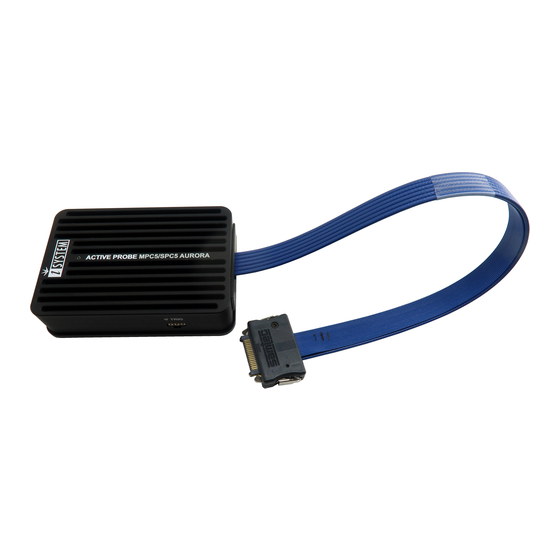
Page 6: Package Content
Package content The RH850 Aurora Active Probe is delivered with the following components: RH850 Aurora 1m FNet Cable User Manual Active Probe Ordering code: Ordering code: IC57176 BB-FNET-100... -
Page 7: Specifications
5% to 80% RH MECHANICAL Size 80 x 55 x 18 mm Weight 0.125 kg OPERATION Communication iSYSTEM proprietary FNet interface to BlueBox Debug signal valid input 3.3V (max. 3.6V) voltage range Power consumption Max. 1.5W (dependent on operation mode) Number of supported... -
Page 8: Operation
Operation Device overview Device description A – RH850 Aurora target pinout: Signal Signal Signal Signal Signal Signal Direction Description Description Direction Reference AGBT TX0_P TX0_P Vref Voltage AGBT TX0_N TX0_N LPDCLK JTAG Ground Reserved AGBT TX1_P TX1_P LPDI JTAG AGBT TX1_N TX1_N LPDO JTAG... - Page 9 When powering on the system, switch the iC5700 on before powering on the target system. When powering down the system, power off the target before powering off the iC5700! Use only original iSYSTEM accessories for powering and connecting with the iC5700. Consult with iSYSTEM before attempting to use any other accessory.
-
Page 10: 14-Pin 2.54 Mm Lpd Adapter
14-pin 2.54 mm LPD Adapter Ordering code IASAM34RH850PIN14 Adapter must be ordered separately to connect to the target featuring 14-pin 2.54mm pitch LPD target debug connector. This adapter can be used in conjunction with the iC6000 DTM Aurora/LPD module (IC60024-1) and RH850 Aurora Active Prove (Ordering code IC57176). The following pinout is valid on the target side: Signal Signal... -
Page 11: Active Probe And The Ic5700 Connecting Guidelines
If a cable longer than 1.0m is required (for example when debugging an ECU in a vehicle or a confined space), optional 3.0m and 5.0m FNet Micro cables are available from iSYSTEM. Although it looks similar to the HDMI interface, the FNet Port is not compatible with HDMI or any HDMI accessories. -
Page 12: Setting Debug Interface Voltage Levels
Setting Debug Interface Voltage Levels The voltage levels for the debug interface are configured within winIDEA via Hardware menu / CPU Options / Hardware. When the microcontroller target supplies 5.0V to the Vref signal (pin 1), use the radio-button selection to select the Vref option instead. -
Page 13: Further Active Probe Settings
Further Active Probe Settings This section describes winIDEA settings distinct to the RH850 Aurora Active Probe. BlueBox iC5700 is capable of connecting to Renesas RH850 target devices through its installed DTM module and an appropriate debug adapter 14-pin 2.54 mm LPD Adapter (Ordering code: IASAM34RH850PIN14). -
Page 14: Lane Link Speed
Lane link speed By default the lowest Aurora link speed is set which ensures the most likely working trace operation. Note that this setting directly impacts on Aurora trace interface bandwidth. The higher the speed, more trace information per time unit can be broadcasted over the interface. Hence, once the Analyzer trace operation (e.g. -
Page 15: Accessories
3.0m FNet Cable BB-FNET-500 5.0m FNet Cable IASAM34MPCPIN14 14-pin 2.54 mm JTAG Adapter Please refer to the iC5700 BlueBox for all current iC5700 Accessories. Find more information on www.isystem.com or contact sales@isystem.com. To reach for technical support please visit www.isystem.com/support. - Page 16 Whilst iSYSTEM reserves the right to make changes to its products and/or the specifications detailed herein, it does not make any representations or commitments to update this document.
Need help?
Do you have a question about the Aurora RH850 and is the answer not in the manual?
Questions and answers