
Related Manuals for FLIR Quasar Gen III CP-6302 Series


Summary of Contents for FLIR Quasar Gen III CP-6302 Series
- Page 1 Quasar™ Gen III User Guide CP-6302-30-R CP-6302-31-P CP-6302-31-I Quasar CP-6302 Range User Guide - Ver. 8 - January 31, 2021 This document does not contain any export-controlled information.
- Page 2 © 2021 FLIR Systems, Inc All rights reserved worldwide. No parts of this manual, in whole or in part, may be copied, photocopied, translated, or transmitted to any electronic medium or machine readable form without the prior written permission of FLIR Systems, Inc.
- Page 3 Product Registration and Warranty Information Register your Product with FLIR at https://customer.flir.com. For warranty information, see https://www.flir.com/support-center/warranty/security/flir-security-product- warranties/. Quasar CP-6302 Range User Guide - Ver. 8 - January 31, 2021 This document does not contain any export-controlled information.
-
Page 4: Table Of Contents
Table of Contents 1. Document Scope and Purpose ....................1 2. Accessing Camera Information from the Web ................. 5 3. Overview ............................6 Features ..........................7 Package Contents ....................... 8 Camera Dimensions ......................9 System Requirements ....................... 10 4. Installation ..........................11 5. - Page 5 Table of Contents 5.3.5.1 SD Card ........................45 5.3.5.2 Network Share ......................47 5.3.5.3 Recording ........................48 5.3.6 Motion Detection ....................49 5.3.7 Schedule ......................52 5.3.8 File Location ......................53 5.3.9 Maintenance ......................53 5.3.9.1 Log File ........................53 5.3.9.2 User Information ......................
- Page 6 Table of Contents 5.6.3.1 White Balance ......................83 5.6.3.2 Backlight Compensation .................... 83 5.6.3.3 WDR Function ......................84 5.6.3.4 Noise Reduction Settings ................... 84 5.6.4 IR Function ......................85 5.6.5 Misc. Screen ......................86 PTZ Tab ..........................88 5.7.1 Preset ........................89 5.7.2 Pattern ........................
-
Page 7: Document Scope And Purpose
DIsclaimer Avis de non-responsabilité Users of FLIR products accept full Il incombe aux utilisateurs des produits FLIR de vérifier responsibility for ensuring the suitability and que ces produits sont adaptés et d'étudier le rôle des considering the role of the product detection capacités et limites de détection du produit appliqués... - Page 8 FLIR products. Un Conseil correspond à une information et aux bonnes pratiques utiles ou apportant un avantage supplémentaire pour l'installation et l'utilisation des produits FLIR. Quasar CP-6302 Range User Guide - Ver. 8 - January 31, 2021 This document does not contain any export-controlled information.
- Page 9 Document Scope and Purpose General Cautions and Warnings Précautions et avertissements d'ordre général This section contains information that indicates a Cette section contient des informations procedure or condition where there are potential indiquant qu'une procédure ou condition hazards. présente des risques potentiels. SAVE ALL SAFETY AND OPERATING INSTRUCTIONS CONSERVEZ TOUTES LES FOR FUTURE USE.
- Page 10 Document Scope and Purpose Caution: · Do not drop the camera or subject it to physical shock. · Do not touch sensor modules with fingers. If cleaning is necessary, use a clean cloth with a bit of ethanol and wipe it gently. If the camera will not be used for an extended period of time, put on the lens cap to protect the sensor from dirt.
-
Page 11: Accessing Camera Information From The Web
Accessing Camera Information from the Web Accessing Camera Information from the You will find the latest information, versions of documentation and releases of software on the FLIR website. Quasar CP-6302 Range User Guide - Ver. 8 - January 31, 2021... -
Page 12: Overview
Refer to the Latitude online help for information regarding configuring camera settings. Attention: Si vous utilisez le logiciel de gestion de vidéo Latitude de FLIR, nous vous conseillons de configurer les paramètres de la caméra via l'AdminCenter. En effet, l'interface Internet de la caméra peut être remplacée par les paramètres Latitude. -
Page 13: Features
Overview Features · · · 10x digital zoom and 1/2.8” Sony Progressive Four encoder streams 30x optical zoom scan CMOS sensor · · · Low-lux mode True day/night (ICR) PTZ tracking · · · Infrared LED illuminator IR coverage up to 200m IR illumination adjusted by (see Note 1) (see Note 1) -
Page 14: Package Contents
Overview Package Contents Before proceeding, check that the box contains the items listed here. If any item is missing or has defects, do not install or operate the product. Contact your dealer for assistance. Note: Package Contents vary slightly between models - See Installation Manual. 2-Pin 12VDC Power 3-Pin 24VAC Power Terminal Block... -
Page 15: Camera Dimensions
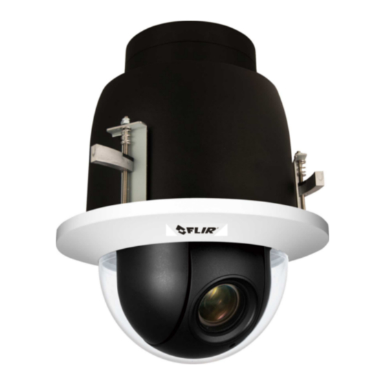
Overview Camera Dimensions Following are the camera’s dimensions. CP-6302-30-R CP-6302-30-P CP-6302-31-I Quasar CP-6302 Range User Guide - Ver. 8 - January 31, 2021 This document does not contain any export-controlled information. -
Page 16: System Requirements
Overview Notes: 1. The P and R models are supplied with a clear dome. 2. 30R Recessed model has different top cover. System Requirements To access the camera via a web browser, ensure that your PC has the proper network connection and meets system requirements as described below. -
Page 17: Installation
Installation Installation This camera is designed for indoor and outdoor installation*. Observe the following installation recommendations: · Always use weatherproof equipment, such as boxes, receptacles, connectors, etc. where appropriate. · For electrical wiring, use the properly rated sheathed cables for conditions to which the cable will be exposed (for example, moisture, heat, UV, physical requirements, etc.). -
Page 18: Configuration And Operation
· PTZ Tab · Logout Additionally, if FLIR’s Latitude VMS is used, many of the configurations and features of FLIR’s VMS provide configuration and automation of the camera. Browser-Based Viewer Introduction The figure below illustrates the camera’s browser-based user interface. -
Page 19: Live Screen
Configuration and Operation · Settings Button Clicking the Settings button opens the Settings screen, whose sidebar which includes four System, Streaming, Camera, and PTZ settings. · System The administrator can configure settings for basic system parameters, security, network operation, events, recording, storage, system maintenance, and more. ·... - Page 20 Configuration and Operation To exit Fullscreen mode 1. Do one of the following: a. Press the Escape key on your keyboard. The Live View screen is displayed in the monitor screen. b. Right-click the screen. Click Normal view. The Live View screen is displayed in the monitor screen. To view the Live View screen in Center mode 1.
- Page 21 Configuration and Operation Video Streaming Restart/Stop Press the Stop button to disable video streaming and to display the live video as black. Press Restart to show the live video again. Record/Pause Pressing the Recording button stores recordings from the Live View in the location specified on the local hard drive, which can be configured in the File Location screen.
-
Page 22: System Tab
Configuration and Operation · Use the PT control panel to move the camera and to run Presets, Pattern lines, and Sequence paths. · Select a Preset/Pattern/Sequence line. · Preset - Select a number from 1-10 from the drop-down menu. Click here for details about this function. -
Page 23: System
Configuration and Operation Details of these settings are specified in the following sections: System Security Network Events Setup Edge Recording Motion Detection Schedule File Location Maintenance Import/Export Note: The System screen is accessible only by the Administrator. 5.3.1 System The System screen is used for entering the camera’s friendly name and date and time settings. Click the System tab in the sidebar. -
Page 24: Security
Configuration and Operation Time format Enables a choice of formats: either year, month and day (yyyy/mm/dd) or day, month and year (dd/mm/yyyy). Sync with Computer Time Select this button to synchronize video date and time display with the PC. You can change the PC date and time in the respective text box. - Page 25 Configuration and Operation Note: The following characters are valid: A-Z, a-z, 0-9,!#$%&’-.@^_~. Add user The user name and passwords are limited to 14 characters. There is a maximum of 20 user accounts. To add a new user 1. Type the new user name and password in the respective fields. 2.
-
Page 26: Https
Configuration and Operation Click SAVE. Streaming Authentication Setting From the drop-down list, select one of the following options: · Disable – Do not use streaming authentication (default setting). · Basic – A form of authentication that uses unencrypted base64 encoding. Basic Authentication should generally only be used where transport layer security, such as HTTPS, is provided. - Page 27 Configuration and Operation · Locality – Enter other geographical information. · Organization – Enter the name of the organization to which the entity identified in Common Name belongs. · Organizational Unit – Enter the name of the organizational unit to which the entity identified in the Common Name field belongs.
-
Page 28: Ip Filter
Configuration and Operation Note: The self-signed certificate does not provide the same level of security as a CA-issued certificate. 5.3.2.3 IP Filter The IP filter restricts access to the camera by denying/allowing specific IP addresses. Click the IP Filter tab under the category Security in the sidebar to display the following page. IP Filter Screen To enable the IP filter 1. -
Page 29: Network
Configuration and Operation IEEE 802.1X/EAP-TLS Screen CA Certificate The CA certificate is created by the Certificate Authority for the purpose of validating itself. Click Browse to locate the file and UPLOAD to upload the certificate to check the server’s identity. Client Certificate Upload the Client Certificate to authenticate the camera. -
Page 30: Basic
Get IP address automatically If you select Get IP address automatically, you can use the DNA utility, which can be accessed from the FLIR website - see Accessing Camera Information from the Web, to obtain the IP address from a DHCP server on the network. - Page 31 Configuration and Operation Note: For future reference, record the camera’s MAC address, which is found on the camera label. Use fixed IP address The camera’s default setting is Use fixed IP address. Refer to the Using the DNA Utility to Search and Access the Camera section of the Quasar Gen III CP-6302 Range Installation Manual to log in with the default IP address.
-
Page 32: Qos
Configuration and Operation Click SAVE when finished. IPv6 Address Configuration To enable IPv6 1. Check Enable IPv6. 2. In the Address text box, enter the unit's IPv6 IP Address. 5.3.3.2 QoS (Quality of Service) provides differentiated service levels for different types of traffic packets and guarantees delivery of priority services during periods of network congestion. - Page 33 Configuration and Operation SNMP Settings Screen SNMP v1/v2 · Enable SNMP v1 or Enable SNMP v2 – Select the version of SNMP (v1 or v2) to use by checking the relevant box. · Read Community – Specify the community name that has read-only access to all supported SNMP objects.
-
Page 34: Upnp
Configuration and Operation Traps are used by the camera to send messages to a management system for important events or status changes. · Enable traps – Check this box to activate trap reporting. · Trap address – Enter the IP address of the management server. ·... -
Page 35: Ddns
Configuration and Operation Note: To enable this function, make sure that your router supports UPnP and that it is activated. · Friendly name – Enter the name for the camera for identification. Click SAVE when finished. 5.3.3.5 DDNS Dynamic Domain Name System (DDNS) allows a host name to be constantly synchronized with a dynamic IP address. -
Page 36: Mail
Configuration and Operation 5.3.3.6 Mail Simple Mail Transfer Protocol (SMTP) is a protocol for sending e-mail messages between servers. It is a relatively simple, text-based protocol, where a text message is transferred to one or more specified recipients. The Administrator can send an e-mail via Simple Mail Transfer Protocol (SMTP) when an alarm is triggered. -
Page 37: Http
Configuration and Operation For each server, enter the server IP address, server port number, user name, password, and remote folder path. Settings are entered in the System > Network > FTP screen: FTP Screen To use passive mode, select the 1st FTP passive mode or 2nd FTP passive mode checkbox for the respective server. -
Page 38: Events Setup
Configuration and Operation Two notification server accounts (Alarm Triggered and Motion Detection) can be set up and sent to the specified HTTP servers. For each server, enter the HTTP details, including server IP address, user name, and password. Settings are entered in the System > Network > HTTP screen: HTTP Screen Click SAVE when finished. - Page 39 Configuration and Operation IO Screen Alarm Switch Four alarms are available. For each alarm, the Administrator can select from the following options: · Select Off to disable an alarm. · Select On to enable an alarm (default setting). · Select By Schedule to set a schedule. Then click Please Select to select up to 10 schedules from the drop-down list that opens.
-
Page 40: Network Failure Detection
Configuration and Operation · Upload image by E-Mail – Select this checkbox to assign an e-mail address for sending the image captured by a triggered alarm. The e-mail address is entered in the Mail screen. · Send HTTP notification – Select this checkbox to send a notification by HTTP. ·... -
Page 41: Tampering
Configuration and Operation Detection Switch The Administrator can select from the following options: · Select Off to disable an alarm (default setting). · Select On to enable an alarm. · Select By Schedule to set a schedule. Then click Please Select to select up to 10 schedules from the drop-down list that opens. - Page 42 Configuration and Operation Tampering Screen Tampering Indication Bar The Tampering Indication bar gives the user a visual display of the threshold for how much Tampering is accruing. This indication bar will be effected by the sensitivity settings mentioned below. Tampering Alarm Four alarms are available.
- Page 43 Configuration and Operation · Enable alarm output – Check this box and select the predefined type of alarm output (low or high) to enable alarm relay when a network failure is detected. · Enable alarm output – Check this box and select the predefined type of alarm output (low or high) to enable alarm relay when a network failure is detected.
-
Page 44: Periodic Event
Configuration and Operation 5.3.4.4 Periodic Event The Periodic Event screen is used to specify an alarm to be triggered at a specified time interval. Periodic Event Screen Periodic Event Select Off or On to activate this function. The default is Off. Time Interval In the Minimum interval text box, enter the number of seconds for the minimum interval between alarms. -
Page 45: Manual Trigger
Configuration and Operation · Overwrite The original image in the FTP site will be overwritten by the new uploaded file with a static filename. Click SAVE after configuring the settings. 5.3.4.5 Manual Trigger The Manual Trigger screen is used to specify an alarm to be manually triggered. You can define action to take when an alarm occurs from the System >... -
Page 46: Audio Detection
Configuration and Operation File Name · File Name – Enter a file name in the field, for example image.jpg. The uploaded image’s file name format is set in this section. Select one that meets your requirements. · Add date/time suffix (default setting) File name: imageYYMMDD_HHNNSS_XX.jpg Y: Year, M: Month, D: Day H: Hour, N: Minute, S: Second... - Page 47 Configuration and Operation Detection Switch The Administrator can select from the following options: · Select Off to disable audio (default setting). · Select On to enable audio. · Select By Schedule to set a schedule. Then click Please Select to select up to 10 schedules from the drop-down list that opens.
-
Page 48: Triggered Actions
Configuration and Operation · Add sequence number suffix (no maximum value) File name: imageXXXXXXX.jpg X: Sequence Number · Add sequence number suffix (limited value) File Name: imageXX.jpg X: Sequence Number The file name suffix ends at the number being set. For example, if the setting is up to “10,” the file name will start from 00, end at 10, and then start over again. - Page 49 Configuration and Operation Upload Image by FTP Settings Note: Images can be sent by FTP only when MJPEG is selected as the video stream from the Video Configuration screen. Specify the FTP address to use from the drop-down menu. Select the number of frames for the pre-trigger and post-trigger buffers from the drop-down menu of 1-20 frames.
- Page 50 Configuration and Operation · Check the Continuous image upload box if you wish to upload an image by e-mail for a defined period of time or while the trigger is active. Select one of the following options: · To specify the length of time for the upload, select Upload for and enter the number of seconds in the text box.
-
Page 51: Edge Recording
Configuration and Operation 5.3.5 Edge Recording The Events Recording tab is used for configuring settings for the various methods used for event notification. The tab includes the following screens: SD Card Network Share Recording 5.3.5.1 SD Card You can locally record up to 128GB on a Class 10 microSDXC card (Min recommended 4GB). The SD Card page shows the capacity information of the memory card and a recording list of all the recording files saved on the card. - Page 52 Configuration and Operation Disk Cleanup Setting Enable automatic recording cleanup by selecting Enable automatic disk cleanup. From the pull-down menu, specify the minimum length of time over which to remove recordings. For example, remove recordings over 10 days old. Enter the percent of disk capacity used in order to remove the oldest recordings.
-
Page 53: Network Share
Configuration and Operation 5.3.5.2 Network Share The Network Share screen shows the capacity information of the Network Attached Storage (NAS) disk and provides a list of all the recording files saved on the disk. Network Share Screen You can also format the disk and implement automatic recording cleanup on this page. To implement NAS recording, see Recording. -
Page 54: Recording
Configuration and Operation Disk Cleanup Setting Enable automatic recording cleanup by selecting Enable automatic disk cleanup. From the pull-down menu, specify the minimum length of time over which to remove recordings. For example, remove recordings over 10 days old. Enter the percent of disk capacity used in order to remove the oldest recordings. -
Page 55: Motion Detection
Configuration and Operation In the Recording Storage section, select the recording device: SD Card or Network Share. Note: It is not recommend to record with the microSD/SDXC card for 24/7 continuously, as it may not be able to support long term continuous data read/write. Contact the manufacturer of the microSD card for information regarding its reliability and life expectancy. - Page 56 Configuration and Operation Motion Detection Screen Detected motion is displayed in the Motion Indication Bar. After motion detection has been activated, the bar is divided into 10 segments; each one representing a sensitivity level. Once the motion exceeds the set sensitivity level, the bar turns from green to red. Note: If you are using Latitude, it is recommended to set the motion detection from Admin Center.
- Page 57 Configuration and Operation To activate Motion Detection 1. From the Motion Detection drop-down list, select a number from 1 to 4. 2. Do one of the following for each detection region: · Select On for continuous detection. · Select By schedule for scheduled detection. For instructions how to set a schedule for motion detection, refer to Schedule.
-
Page 58: Schedule
Configuration and Operation Triggered Action The Administrator can specify various alarm actions to take when an alarm is triggered. See the section for a detailed description of the actions. The following options are available: · Enable alarm output 1 – Check this box and select the predefined type of alarm output (low or high) to enable alarm relay when motion is detected. -
Page 59: File Location
Configuration and Operation Note: This application is not the same as the Recording Schedule function. It is not used for recording live video. To create a new schedule or edit an existing schedule 1. Select the appropriate checkbox for the day(s) of the week (Sun, Mon, Tue, Wed, Thu, Fri and Sat) to create a schedule. -
Page 60: User Information
Configuration and Operation System Log Screen 5.3.9.2 User Information The Administrator can view each user’s login information and privileges in the User information screen shown below. View User Login Information Click GET USER INFORMATION to see each user’s details. For example: Admin: 1234. This indicates that the user’s login username is Admin and the password is 1234. -
Page 61: Factory Default
Configuration and Operation User Information – Get User Privacy In the screen above, both Admin and User are granted privileges of I/O access, Camera control, Talk and Listen, which are the maximum privileges that can be granted. Note: User credentials and privileges are set in the User screen. -
Page 62: Software Version
Configuration and Operation Note: The IP address and all other settings will be restored to factory default settings. Partial Restore Click PARTIAL RESTORE to restore the factory default settings, but save the network settings. The system restarts in 30 seconds. Partial Restore Screen Reboot Click REBOOT to restart the system without changing current settings. -
Page 63: Software Upgrade
Configuration and Operation 5.3.9.5 Software Upgrade The Software Upgrade screen enables you to select a software file to upload. Software Upgrade Screen Note: 1. Make sure that the software upgrade file is available before performing a software upgrade. 2. Do not change the file name. If you change the upgrade file name, the system will fail to find the file. -
Page 64: Parameters
Configuration and Operation 3. Click UPGRADE. The system verifies that the upgrade file exists and begins to upload the file. The upgrade status bar is displayed on the page. When the upgrade process is completed, the Live page is displayed. 4. -
Page 65: Import/Export
Configuration and Operation Import/Export From the Import/Export screen you can export configuration files to a specified location and retrieve data by uploading an existing configuration file to the camera. Import/Export Screen To export a configuration file 1. Click EXPORT. An information bar opens. File Download Screen 2. -
Page 66: Video Configuration
Configuration and Operation 5.5.1 Video Configuration The Video Configuration screen is used for configuring most video settings. The selected encoding type (video compression) determines what settings are available. By default, the camera is configured with Stream 1 and Stream 2 enabled at 1920 x 1080 fps. Video Configuration Screen 5.5.1.1 Video Resolutions... -
Page 67: Single-Stream H.265
Configuration and Operation Note: 1. The performance on Streams 2, 3, and 4 depends on the combination and settings of each stream configured before it. For example, Stream 4 performance depends on the settings for Streams 1, 2, and 3. Stream 3 performance depends on the settings for Streams 1 and 2. - Page 68 Configuration and Operation 2. From the Resolution drop-down menu, select the desired resolution. A maximum 25/30 frames per seconds is available when selecting WDR 2 Shutter (PAL) or WDR 2 Shutter (NTSC). A maximum 50/60 frames per second is available when selecting 50 fps (PAL) or 60 fps (NTSC). The default setting is 1920 x 1080.
-
Page 69: Single-Stream H.264
Configuration and Operation 8. Move the Encoding Priority slider to a value between 1 (low bit rate) to 10 (high picture quality). This function enables the user to adjust the quality of the picture along a single axis.The default is 7. -
Page 70: Dual-Stream
Configuration and Operation Note: Images can be sent by FTP or email only when MJPEG steaming is selected as one of the streams. 5.5.1.1.4 Dual-Stream From the Resolution drop-down menu, select the desired resolution. A maximum 25/30 frames per seconds is available when selecting WDR 2 Shutter (PAL) or WDR 2 Shutter (NTSC). A maximum 50/60 frames per second is available when selecting 50 fps (PAL) or 60 fps (NTSC). - Page 71 Configuration and Operation H.265/H.264/MJPEG + H.265/H.264/MJPEG Stream 1 Stream 2 1920 x 1080 1280 x 1024 1280 x 720 1024 x 768 800 x 600 1280 x 1024 720 x 576 (PAL) 720 x 480 (NTSC) 640 x 480 352 x 288 (PAL) 352 x 240 (NTSC) 320 x 240 1920 x 1080...
- Page 72 Configuration and Operation H.265/H.264/MJPEG + H.265/H.264/MJPEG Stream 1 Stream 2 1920 x 1080 1280 x 1024 1024 x 768 800 x 600 720 x 576 (PAL) 800 x 600 720 x 480 (NTSC) 640 x 480 352 x 288 (PAL) 352 x 240 (NTSC) 320 x 240 1920 x 1080...
-
Page 73: Triple-Stream
Configuration and Operation 5.5.1.1.5 Triple-Stream From the Resolution drop-down menu, select the desired resolution. Maximum 25/30 frames per seconds is available when selecting WDR 2 Shutter (PAL) or WDR 2 Shutter (NTSC). Maximum 50/60 frames per second is available when selecting 50 fps (PAL) or 60 fps (NTSC). The default setting is 1920 x 1080. Note: The default bit rate for Stream 1 and Stream 2 is 4096 bps. - Page 74 Configuration and Operation H.265/H.264/MJPEG + H.265/H.264/MJPEG + H.265/H.264/MJPEG Stream 1 Stream 2 Stream 3 1920 x 1080 1280 x 1024 1280 x 720 800 x 600 720 x 576 (PAL) 1280 x 720 1920x1080 - 320x240 720 x 480 (NTSC) 640 x 480 352 x 288 (PAL) 352 x 240 (NTSC)
-
Page 75: Quad-Stream
Configuration and Operation H.265/H.264/MJPEG + H.265/H.264/MJPEG + H.265/H.264/MJPEG Stream 1 Stream 2 Stream 3 1920 x 1080 1280 x 1024 1024 x 768 800 x 600 720 x 576 (PAL) 720 x 576 (PAL) 1920x1080 - 320x240 720 x 480 (NTSC) 720 x 480 (NTSC) 640 x 480 352 x 288 (PAL) - Page 76 Configuration and Operation H.265/H.264/MJPEG + H.265/H.264/MJPEG + H.265/H.264/MJPEG + H.265/H.264/MJPEG Stream 1 Stream 2 Stream 3 Stream 4 1920 x 1080 1280 x 1024 1280 x 720 1024 x 768 800 x 600 1920 x 1080 1920x1080 - 320x240 1920x1080 - 320x240 720 x 576 (PAL) 720 x 480 (NTSC) 640 x 480...
- Page 77 Configuration and Operation H.265/H.264/MJPEG + H.265/H.264/MJPEG + H.265/H.264/MJPEG + H.265/H.264/MJPEG Stream 1 Stream 2 Stream 3 Stream 4 1920 x 1080 1280 x 1024 1280 x 720 1024 x 768 800 x 600 1024 x 768 1920x1080 - 320x240 1920x1080 - 320x240 720 x 576 (PAL) 720 x 480 (NTSC) 640 x 480...
- Page 78 Configuration and Operation H.265/H.264/MJPEG + H.265/H.264/MJPEG + H.265/H.264/MJPEG + H.265/H.264/MJPEG Stream 1 Stream 2 Stream 3 Stream 4 1920 x 1080 1280 x 1024 1280 x 720 1024 x 768 800 x 600 640 x 480 1920x1080 - 320x240 1920x1080 - 320x240 720 x 576 (PAL) 720 x 480 (NTSC) 640 x 480...
-
Page 79: Video Rotation
Configuration and Operation 5.5.2 Video Rotation The Video Rotation screen enables you to flip the video and select the rotation angle. Video Rotation Screen From the Mirror drop-down menu, select Yes or No. Yes reverses the image along its vertical axis. Source Image Before Reversing the Image Image after Reversal From the Rotate Type drop-down menu, select 0, 90, 180, or 270 (degrees). -
Page 80: Video Text Overlay
Configuration and Operation 5.5.3 Video Text Overlay The Video Text Overlay screen enables you configure settings for the text displayed over the live video. Select the relevant checkbox for the data to include in the on-screen display: Overlay Type · Include Date &... -
Page 81: Video Ocx Protocol
Configuration and Operation Image Overlay Setting · Image Transparency 255. The lower the value, the more transparent the image will be. Click SET when finished. Note: The file must be saved as an 8-bit .bmp file.The length should be a multiple of 32 (for example, 320 pixels) and the width should be a multiple of 4 (for example 40 pixels). -
Page 82: Audio
Configuration and Operation Note: The TTL (Time to Live) value instructs the network router whether or not to discard a packet and is reduced every time the datagram is forwarded to another router. The packet is discarded if the TTL reaches 0. The recommended value is 64. Click SAVE to confirm the settings. -
Page 83: Camera Tab
Configuration and Operation Server Gain Setting Set the audio input/output gain levels for sound amplification. The sound will be turned off if the input or output gain is set to Mute. · The audio input gain is adjustable from 1-10. The default setting is 3. ·... -
Page 84: Exposure Screen
Configuration and Operation 5.6.1 Exposure Screen The Exposure screen is used to configure lens settings and exposure modes. The exposure is the amount of light received by the image sensor and is determined by the amount of exposure by the sensor (shutter speed), and other exposure parameters. -
Page 85: P-Iris Priority Mode
Configuration and Operation Caution: Using a slow shutter speed causes moving objects to be blurred. Attention: L'utilisation de vitesses d'obturation faibles peut rendre les objets en mouvement flous. 5.6.1.2 P-Iris Priority Mode In P-iris Priority mode, the iris does not adjust, regardless of the light level. If, however, the light level goes below the P-iris setting, the iris will fully open automatically to the optimal iris exposure if the Auto Detect radial button is selected. -
Page 86: Auto Shutter Mode
Configuration and Operation · Min Shutter Speed – When selecting this mode, the shutter is completely open and the exposure priority is given to the iris. Shutter speed and AGC circuit function automatically in cooperating with the iris to achieve a consistent exposure output. The following table lists the options: Iris Priority Min Shutter Speed... -
Page 87: Manual Mode
Configuration and Operation Shutter Priority Speed 1/300 1/350 1/215 1/250 1/150 1/180 1/120 1/120 1/100 1/100 1/75 1/90 1/50 1/60 1/25 1/30 5.6.1.6 Manual Mode Manual mode is used generally where light levels are fixed and the auto settings do not provide the perfect exposure. -
Page 88: Picture Adjustment
Configuration and Operation · Gain – A nominal video signal level is usually 1-volt peak-to-peak for composite video, 0.7 volts for component or RGB video, or 0.3 volts for the chrominance subsection, at which level a fully saturated picture is transmitted to the acceptor. However, for cases where the video signal is attenuated, a low-noise, high-gain analog amplifier is built into quality video processing equipment. -
Page 89: White Balance
Configuration and Operation Advanced Picture Settings Screen with Backlight Compensation 5.6.3.1 White Balance A camera needs to find a reference color temperature as a way of measuring the quality of a light source for calculating all other colors. The unit for measuring this ratio is in Kelvin (°K) degrees. You can select one of the White Balance control modes according to the operating environment. -
Page 90: Wdr Function
Configuration and Operation 5.6.3.3 WDR Function By default, the camera utilizes digital Wide Dynamic Range (dWDR), which improves the image quality and amount of details in high contrast scenes. Such scenes combine areas with different lighting conditions, where some areas are very bright and others are dark. If this function was not used, the image either would be overexposed or too bright in bright areas and completely dark in dark areas. -
Page 91: Ir Function
Configuration and Operation 2DNR 2DNR (2D Noise Reduction) analyzes individual frames pixel by pixel and frame by frame to eliminate environmental noise and deliver optimized image quality, especially in low-light conditions. 2DNR tends to produce superior results for moving objects when applied to areas in the field of view where movement is present. -
Page 92: Misc. Screen
1. It is recommended that this feature only be used in conditions of extreme cold. 2. The camera must have a Zoom MCU version of T2-L34-I0-180724-02 to support this feature. Please contact FLIR Support to download this file 5.6.5 Misc. Screen The Misc. - Page 93 Configuration and Operation Stabilizer and Shutter (True) WDR. The unit's frame rate is 25/30 fps in this mode.The default setting is WDR 2 Shutter (NTSC). Misc. Screen with True (Multi-Shutter )WDR Enabled Note: After changing the TV Setting, the camera resets automatically. Refresh the page to view the new setting.
-
Page 94: Ptz Tab
Configuration and Operation Selecting WDR 2 Shutter enables True (Multi-Shutter) WDR at 25/30 fps (PAL/NTSC). It is recommended to select WDR 2 Shutter to solve contrast or changing light issues and to enhance the video display quality. This function is used to set a fixed exposure while other parameters can change. In this mode, the camera’s shutter speed works automatically to achieve a consistent video output level in scenes with high contrast or changing light issues. -
Page 95: Preset
Configuration and Operation Click Open to open the iris. Click Reset to reset the iris. 5.7.1 Preset The PTZ tab opens on the Preset screen. Preset Screen On this screen you can program up to 256 Presets to target a specific view in the Live View pane. To program a Preset Point 1. -
Page 96: Auto Pan
Configuration and Operation To move the camera along a Pattern Line 1. Under Pattern run, select the desired Pattern path from the drop-down menu. 2. Click RUN. The camera moves along the recorded Pattern path. To view the camera in full screen mode as it follows the Pattern Line 1. -
Page 97: Sequence
Configuration and Operation 5.7.4 Sequence The Sequence page enables you to define up to eight Sequence lines for the camera image. A Sequence line is an automated series of camera movements from one Preset Point to another, in a pre- determined order, and for configurable time periods. -
Page 98: Home
Configuration and Operation 2. Click GO. The camera moves through each Preset Point sequentially as programmed. To view the camera in full screen 1. Move the cursor onto the Live View pane. 2. Right-click and select Full screen. 3. Double-click to exit Full screen mode. To stop running a Sequence line 1. -
Page 99: Privacy Mask
Configuration and Operation 5.7.7 Privacy Mask From the Privacy Mask page, you can set up to 20 privacy masks. The Privacy Mask function allows concealment of sensitive portions of the camera image to avoid intrusive monitoring. Note: 1. The Flip function on the PTZ Setting screen is automatically disabled when the Privacy Mask function is on. -
Page 100: Rs485
Configuration and Operation Flip You can track an object continuously when it passes under the camera by selecting M.E. (Mechanical) or Image (Digital Flip) mode from the drop-down list. When Flip is enabled, the image is reversed along its horizontal axis. Select Off if you do want to use this function (default setting). ·... -
Page 101: Log Out
Configuration and Operation To configure RS-485 settings 1. From the Protocol drop-down menu, select PelcoD or PelcoP. The default is PelcoD. 2. From the Baudrate drop-down menu, select the desired baud rate. The default is 2400. 3. The Data bits field is disabled. 4. -
Page 102: Appendices
Appendices Appendices · Technical Specifications · Internet Security Settings · Install UPnP Components · Installing and Deleting the Web Player · Deleting Temporary Internet Files Quasar CP-6302 Range User Guide - Ver. 8 - January 31, 2021 This document does not contain any export-controlled information. -
Page 103: Technical Specifications
Technical Specifications 6.1.1 Accessing Camera Information from the Web You will find the latest information, versions of documentation and releases of software on the FLIR website. Quasar CP-6302 Range User Guide - Ver. 8 - January 31, 2021 This document does not contain any export-controlled information. -
Page 104: Internet Security Settings
Appendices Internet Security Settings If ActiveX control installation is blocked, either set Internet security level to default or change ActiveX controls and plug-in settings. To set the default Internet security level 1. Start Internet Explorer (IE). 2. From the Command Bar toolbar, select Tools and select Internet Options from the menu that appears. - Page 105 Appendices ActiveX Controls and Plug-in Settings To create a custom level 1. Start Internet Explorer (IE). 2. From the Command Bar toolbar, select Tools and select Internet Options from the menu that appears. Command Bar Toolbar – Internet Options 3. In the Internet Options window that appears, select the Security tab. 4.
-
Page 106: Install Upnp Components
Appendices Install UPnP Components Follow the instructions below to enable UPnP so that the camera can be discovered and displayed in the Network and Sharing Center. To enable UPnP discovery 1. Click (Start) and select Control Panel. 2. Click Network and Internet (Win 7, 8, or 8.1). 3. - Page 107 Appendices To check that the UPnP Device Host services are running 1. Click (Start) and type in the Search programs and files field services.msc and then select services.msc from the displayed Programs. The Services manager dialog box appears. Services Manager Dialog Box 2.
-
Page 108: Installing And Deleting The Web Player
Appendices Installing and Deleting the Web Player The Quasar Player enables you to view the camera’s user interface. After logging into the unit, the following information bar is displayed: "Run Quasar Player" Information Bar Click Allow. If the Quasar Player has been loaded previously, the Live View window opens. If this is a first-time installation of the camera, the Quasar Player installation wizard opens after accessing the camera. - Page 109 Appendices 4. Do one of the following: a. On the banner bar, click Uninstall (Win 7, 8, or 8.1). b. Right-click the program, click Uninstall/Change (Win 10). 5. When prompted to confirm the Uninstall, click Yes. 6. After deleting the previous player file, you must clear your computer’s cache memory. To clear your computer’s cache memory 1.
-
Page 110: Deleting Temporary Internet Files
Appendices Deleting Temporary Internet Files To improve browser performance, it is recommended to clean up all of the temporary Internet files. To delete temporary Internet files 1. In Internet Explorer (IE), from the Command Bar toolbar, click Tools and select Internet Options from the menu that appears. - Page 111 FLIR Systems, Inc. 6769 Hollister Ave Goleta, CA 93117 Corporate Headquarters FLIR Systems, Inc. 27700 SW Parkway Ave. Wilsonville, OR 97070 Support: https://www.flir.com/support/ product.enterprise.support@flir.com Document: Quasar Gen III CP-6302 Range User Guide Version: Ver. 8 Date: January 31, 2021 This document does not contain any export-controlled information.
Need help?
Do you have a question about the Quasar Gen III CP-6302 Series and is the answer not in the manual?
Questions and answers