
Related Manuals for FLIR ORION SC7000


Summary of Contents for FLIR ORION SC7000
- Page 1 DCOO5U-F ORION SC7000 User Manual Advanced Thermal Solutions ORION SC7000 User Manual...
- Page 2 ORION SC7000 User Manual Advanced Thermal Solutions PAGE LEFT INTENTIONNALY BLANK DCOO5U-F ORION SC7000 User Manual Page 2...
-
Page 3: Table Of Contents
8.5. Filters ......................31 Diagnostics ..................32 9.1. Diagnostic table .................... 32 9.2. How to contact after sales service? ..............34 10. Technical data ..................35 10.1. Mechanical interface ..................37 10.2. Electrical interface ..................40 DCOO5U-F ORION SC7000 User Manual Page 3... -
Page 4: For Your Safety
Advanced Thermal Solutions 2. For your safety To ensure no damage to your FLIR equipment, you or other people, carefully read the following recommendations before using your equipment. Then keep these instructions in a place easily accessible to all those which will have to use... -
Page 5: Precautions
ORION SC7000 User Manual Advanced Thermal Solutions 3. Precautions To maximize the lifetime and get the best use of your FLIR equipment, observe the following instructions when storing or using it. Keep it dry Avoid abrupt changes This device will be damaged if... -
Page 6: General Overview
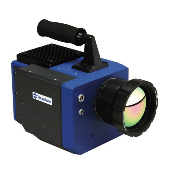
Advanced Thermal Solutions 4. General Overview 4.1. Product Overview The Orion SC7000 system is an infrared multispectral imager capable of producing IR sub-band images at video rate within the SW-MWIR or LWIR region, depending on your configuration. This high performance system uses... - Page 7 1 Camera Characterization file Optional : 1 Cam LINK Frame Grabber (Optional) 1 Computer for camera command and image acquisition. (Optional) 1 or more additional lenses (Optional) 1 Tripod (Optional) Splitter box for harsh environments (Optional) DCOO5U-F ORION SC7000 User Manual Page 7...
-
Page 8: Camera Description
Temperature sensor connector for temperature compensated lenses TITANIUM 590VL version Giga Ethernet connector ON / OFF button Video output connector Lockin connector (optional) Trigger connector Power Input connecor CamLink connector TITANIUM 590VL version DCOO5U-F ORION SC7000 User Manual Page 8... - Page 9 ORION SC7000 User Manual Advanced Thermal Solutions Threads for fixing on a plate Tripod Thread TITANIUM 590VL version NB: Three different camera back-panels are available (hereafter described) DCOO5U-F ORION SC7000 User Manual Page 9...
- Page 10 NB: Configuration #3 is dedicated to harsh environments. It comes with the following extension module for: ON / OFF button RS232 command Analog Video Connection to Camera Trigger OUT connector IRIG-B connector Power IN connector Trigger IN connector Trigger/Genlock selector Genlock IN connector DCOO5U-F ORION SC7000 User Manual Page 10...
-
Page 11: Starting With The Camera
After a few seconds, 10s typically, the system displays a pattern on the video output. Some configuration presents a switch button that does not need to be hold for 2 seconds. Figure 1 : Pattern DCOO5U-F ORION SC7000 User Manual Page 11... -
Page 12: Pointing And Focusing
Handle gently any additional lenses, as well as the connectors. These parts are particularly fragile. Connection of cables The connection and disconnection of the cables can be carried out at any time, camera on or off, computer on or off. DCOO5U-F ORION SC7000 User Manual Page 12... -
Page 13: Training
This equipment and its use require knowledge of the field of infrared thermography in order to make best use of the camera and the processing of acquisitions. FLIR offers training schemes allowing you to use this equipment to its full potential. contact... -
Page 14: Using Your Camera
7.1 for the maintenance of optics Remove the caps of the lenses that you wish to use and place it gently in the bayonet or thread. Gently insert the lens and turn it clockwise. DCOO5U-F ORION SC7000 User Manual Page 14... -
Page 15: Removing The Lens Interface
Check that optics is clean before assembling it in the camera. See section 7.1 for the maintenance of optics Unscrew the six screws located around the M80 thread using the appropriate 2.5mm BTR key. DCOO5U-F ORION SC7000 User Manual Page 15... -
Page 16: Filter Wheel
Advanced Thermal Solutions 6.3. Filter wheel Your ORION SC7000 camera comes with a 2x4-slots filter wheel. This wheel can be fitted with several filters from factory. You may also want to upgrade the wheel yourself by fitting some additional filters. - Page 17 1. Remove carefully the optical lens from the camera, 2. Remove carefully the lens interface as mentioned in § 6.2 and place it on a flat clean table as shown below DCOO5U-F ORION SC7000 User Manual Page 17...
- Page 18 ORION SC7000 User Manual Advanced Thermal Solutions 3. Remove the screws holding the stops with a 2.0 flat head screwdriver DCOO5U-F ORION SC7000 User Manual Page 18...
- Page 19 ORION SC7000 User Manual Advanced Thermal Solutions 4. Remove the stops holding the filter slot ring DCOO5U-F ORION SC7000 User Manual Page 19...
- Page 20 ORION SC7000 User Manual Advanced Thermal Solutions 5. Remove the slot ring DCOO5U-F ORION SC7000 User Manual Page 20...
- Page 21 The slot has a depth of 2.1mm, so do not use any spacer for such thick filter, Start by measuring the thickness of your filter with a caliper, DCOO5U-F ORION SC7000 User Manual Page 21...
- Page 22 Peel the needed shims (0.1 mm per shim) as indicated below: Place the cutter blade edge Move cutter blade on the peelable spacer as towards your thumb and peel shown above the shim as shown above DCOO5U-F ORION SC7000 User Manual Page 22...
- Page 23 (1) Place the spacer ring #1 first in the slot (2) Then place carefully the filter on top of the spacer ring #1 (3) Put slot ring according step §6.3.1.5 (4) Follow instructions from step §6.3.1.4 step §6.3.1.1 DCOO5U-F ORION SC7000 User Manual Page 23...
- Page 24 #2 on top of the filter (3) Place carefully the second filter on top of the spacer ring (4) Put the slot ring according to step §6.3.1.5 (5) Follow instructions from step §6.3.1.4 to step §6.3.1.1 DCOO5U-F ORION SC7000 User Manual Page 24...
- Page 25 (1) Place the spacer ring #2 in the slot (5) Then place carefully the filter spacer ring (6) Put slot ring according step §6.3.1.5 (7) Follow instructions from step §6.3.1.4 to step §6.3.1.1 DCOO5U-F ORION SC7000 User Manual Page 25...
- Page 26 (2) Then place carefully the filter spacer ring (3) Put slot ring according step §6.3.1.5 (4) Follow instructions from step §6.3.1.4 to step §6.3.1.1 DCOO5U-F ORION SC7000 User Manual Page 26...
- Page 27 (see example below). 2 filters or 1 filter + 1 sapphire window 1 filter or 1 sapphire window 1 filters or 1 sapphire window 2 filters or 1 filter + 1 sapphire window DCOO5U-F ORION SC7000 User Manual Page 27...
- Page 28 NB: If possible, don’t use Germanium with the 1.5 – 5.1 µm ORION SC7000, since this material does not offer the best performances in this configuration.
-
Page 29: Lockin Connection (Optional)
ORION SC7000 User Manual Advanced Thermal Solutions 6.4. Lockin connection (Optional) To use lockin option, you need an X0502 cable linked to the Orion SC7000 lockin connector. Lockin Input Range 10V peak to peak (AC only). Rand 1 Input Range -5/+5V (AC + DC). -
Page 30: Maintenance
Put the camera in its case and store it in a dry cool place, away from dust. Do not expose the case and its contents to temperatures lower than -40°C (-40°F) or higher than 70°C (158 °F). DCOO5U-F ORION SC7000 User Manual Page 30... -
Page 31: Accessories
FLIR offers a range of additional lenses for the ORION camera. These lenses are accompanied by a data sheet. 8.2. Long cables Several lengths of cable are available, up to 50m. FLIR also offers optical fiber repeaters or Ethernet Gigabit repeaters allowing operation at several hundred meters. -
Page 32: Diagnostics
ORION SC7000 User Manual Advanced Thermal Solutions 9. Diagnostics If your camera does not function exactly as it should, check the following table before consulting FLIR after-sales service or your FLIR representative. 9.1. Diagnostic table Problem Action Surface treatment of lens... - Page 33 Yes Activate the AGC under CIRRUS. Check the AGC parameters (Withdraw all the limitations in gain, offset and ROI). Does video monitor remain black? The problem is solved. Yes Contact FLIR After Sales Service No Live image on Altair camera correctly connected powered? ...
-
Page 34: How To Contact After Sales Service
9.2. How to contact after sales service? Before contacting the after sales service or your representative, note the serial number located on the camera. A FLIR engineer will discuss the procedure with you. FLIR after sales service is reachable at the address: customer@flir.fr... -
Page 35: Technical Data
ORION SC7000 User Manual Advanced Thermal Solutions Technical data DCOO5U-F ORION SC7000 User Manual Page 35... - Page 36 ORION SC7000 User Manual Advanced Thermal Solutions DCOO5U-F ORION SC7000 User Manual Page 36...
-
Page 37: Mechanical Interface
ORION SC7000 User Manual Advanced Thermal Solutions 10.1. Mechanical interface DCOO5U-F ORION SC7000 User Manual Page 37... - Page 38 ORION SC7000 User Manual Advanced Thermal Solutions DCOO5U-F ORION SC7000 User Manual Page 38...
- Page 39 ORION SC7000 User Manual Advanced Thermal Solutions DCOO5U-F ORION SC7000 User Manual Page 39...
-
Page 40: Electrical Interface
Connector reference: LEMO ERP1S306CLN Mating part: LEMO FFA1S306CLAC42Z Signal Characteristic: 75 Ohms Signal Composite_Video SVideo_Chroma SVideo_Lumi 10.2.2. Power supply connector Connector reference: LEMO ECP1S302CLN Mating part: LEMO FFA1S302CLAC52 Signal +12V 10.2.3. Trigger connector DCOO5U-F ORION SC7000 User Manual Page 40... - Page 41 LVTTL – 3.3V 10.2.4. Lockin connector Connector reference: LEMO ECP1S305CLN Mating part: LEMO FFA1S305CLAC42Z Signal Characteristic: 10 MOhms Signal characteristic Lockin 0/+10V AC only Random1 -5/+5V DC + AC Random2 -5/+5V DC + AC DCOO5U-F ORION SC7000 User Manual Page 41...
- Page 42 10.2.5. Camera LINK connector Connector reference: 3M MDR26 Mating cable: Signal Signal Inner Shield Inner Shield Xclk- Xclk+ SerTC+ SerTC- SerTFG- SerTFG+ CC1- CC1+ CC2- CC2+ CC3- CC3+ CC4- CC4+ Inner shield Inner shield DCOO5U-F ORION SC7000 User Manual Page 42...
- Page 43 At each Top Frame, the next image associated with the next NUC Table and integration time (from 1 to 4 max) is available. Data_Frame Data_Clock Data_DX Table 1 Table 2 Table 3 Table 4 Table 1 DCOO5U-F ORION SC7000 User Manual Page 43...
Need help?
Do you have a question about the ORION SC7000 and is the answer not in the manual?
Questions and answers