Table of Contents
Advertisement
Advertisement
Table of Contents

Related Manuals for GAS GAS EC 350F


Summary of Contents for GAS GAS EC 350F
- Page 1 OWNER'S MANUAL 2021 EC 350F Art. no. 3215013en...
- Page 3 GASGAS Motorcycles applies quality assurance processes that lead to the highest possible product quality as defined in the ISO 9001 international quality management standard. Issued by: TÜV Management Service GASGAS Motorcycles GmbH Stallhofnerstraße 3 5230 Mattighofen, Austria This document is valid for the following models: EC 350F EU (F0303U9) *3215013en* 3215013en 10/2020...
-
Page 4: Table Of Contents
TABLE OF CONTENTS 6.20 Unlocking the steering ........ 20 TABLE OF CONTENTS MEANS OF REPRESENTATION ........5 COMBINATION INSTRUMENT........21 Symbols used..........5 Formats used..........5 Combination instrument overview ..... 21 Activation............. 21 SAFETY ADVICE ............6 Message on the combination Use definition –... - Page 5 TABLE OF CONTENTS 11.4 Adjusting the high-speed compression 12.32 Cleaning the chain........69 damping of the shock absorber ....40 12.33 Checking the chain tension ......70 11.5 Adjusting the rebound damping of the 12.34 Adjusting the chain tension ......70 shock absorber ..........
- Page 6 TABLE OF CONTENTS 15.11 Changing the turn signal bulb ....104 23.8 Shock absorber......... 133 15.12 Changing the combination instrument 23.9 Chassis tightening torques ....... 134 battery ............104 SUBSTANCES ............137 15.13 Diagnostics connector......105 AUXILIARY SUBSTANCES ......... 139 COOLING SYSTEM ...........
-
Page 7: Means Of Representation 1
MEANS OF REPRESENTATION 1 Symbols used The meaning of specific symbols is described below. Indicates an expected reaction (e.g., of a work step or a function). Indicates an unexpected reaction (e.g., of a work step or a function). All work marked with this symbol requires specialist knowledge and technical understanding. In the interest of your own safety, have this work performed by an authorized GASGAS Motorcycles workshop. -
Page 8: Safety Advice
2 SAFETY ADVICE Use definition – intended use This vehicle has been designed and built to withstand the normal stresses and strains of racing. This vehicle complies with the currently valid regulations and categories of the top international motorsports organizations. Info This vehicle is only authorized for operation on public roads in the homologated (restricted) version. -
Page 9: Tampering Warning
SAFETY ADVICE 2 Tampering warning Tampering with the noise control system is prohibited. Federal law prohibits the following acts or the causing thereof: The removal or rendering inoperative by any person other than for purposes of servicing, repair, or replacement, of any device or element of design incorporated into any new vehicle for the purpose of noise control prior to its sale or delivery to the ultimate purchaser or while it is in use, or the use of the vehicle after such device or element of design has been removed or rendered inoperative by any person. -
Page 10: Work Rules
2 SAFETY ADVICE Work rules Unless specified otherwise, the ignition must be turned off during all work (models with ignition lock, models with remote key) or the engine must be at a standstill (models without ignition lock or remote key). Special tools are necessary for certain tasks. -
Page 11: Important Notes 3
IMPORTANT NOTES 3 Manufacturer warranty, implied warranty The work specified in the service schedule may only be carried out in an authorized GASGAS Motorcycles workshop and confirmed in the GASGAS Motorcycles Dealer.net, as otherwise all warranty claims will be void. Damage or secondary dam- age caused by tampering with and/or conversions on the vehicle are not covered by the manufacturer warranty. -
Page 12: View Of Vehicle
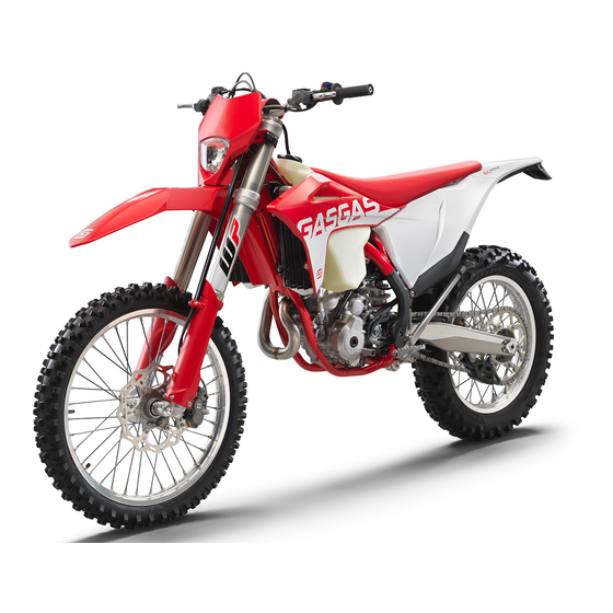
4 VIEW OF VEHICLE View of vehicle, front left (example) F03273-10 Clutch lever ( p. 14) Fuel tank filler cap Air filter box cover Side stand ( p. 19) Engine number ( p. 12) Shift lever ( p. 18) -
Page 13: View Of Vehicle, Rear Right (Example)
VIEW OF VEHICLE 4 View of vehicle, rear right (example) F03274-10 Stop button ( p. 14) Horn button ( p. 15) Light switch ( p. 15) Turn signal switch ( p. 15) Start button ( p. 16) Emergency OFF switch ( p. -
Page 14: Serial Numbers
5 SERIAL NUMBERS Vehicle identification number The vehicle identification number is stamped on the right side of the steering head. 401945-10 Type label The Europe type label is fixed to the front of the steering head. The Canada type label is fixed to the front of the chest tube. -
Page 15: Fork Part Number
SERIAL NUMBERS 5 Fork part number The fork part number is stamped on the inner side of the fork stub. 401947-10 Shock absorber article number Shock absorber article number is stamped on the top of the shock absorber above the adjusting ring towards the engine side. H02222-10... -
Page 16: Controls
6 CONTROLS Clutch lever Clutch lever is fitted on the handlebar on the left. The clutch is activated hydraulically and adjusts itself automatically. F03160-10 Hand brake lever The hand brake lever is fitted on the right side of the handlebar. The hand brake lever is used to activate the front brake. -
Page 17: Horn Button
CONTROLS 6 Horn button Horn button is fitted on the left side of the handlebar. Possible states • The horn button is in the basic position is pressed – The horn is operated in this posi- • The horn button tion. -
Page 18: Start Button
6 CONTROLS Start button Start button is fitted on the right side of the handlebar. Possible states • The start button is in the basic position is pressed – The starter motor is actuated in this • The start button position. -
Page 19: Closing The Fuel Tank Filler Cap
CONTROLS 6 – Press release button , turn the fuel tank filler cap counterclock- wise, and lift it off. F03167-10 6.12 Closing the fuel tank filler cap – Mount fuel tank filler cap and turn it clockwise until the release but- engages. -
Page 20: Idle Speed Adjusting Screw
6 CONTROLS 6.14 Idle speed adjusting screw The idle setting of the throttle valve body substantially influences the vehicle’s starting behavior, a stable idle speed, and the vehicle’s response when the throttle is opened. An engine with a correctly set idle speed is easier to start than an engine with the idle speed set incorrectly. -
Page 21: Foot Brake Lever
CONTROLS 6 6.16 Foot brake lever Foot brake lever is located in front of the right footrest. The rear brake is engaged with the foot brake lever. 401956-10 6.17 Side stand The side stand is attached to the left side of the vehicle. 401943-10 The side stand is used for parking the motorcycle. -
Page 22: Locking The Steering
6 CONTROLS 6.19 Locking the steering Note Danger of damage The parked vehicle can roll away or fall over. – Park the vehicle on a firm and level surface. – Park the vehicle. – Turn handlebar as far as possible to the right. –... -
Page 23: Combination Instrument 7
COMBINATION INSTRUMENT 7 Combination instrument overview Overview of indicator lamps ( p. 16) Left button Display Right button 402819-10 Activation Activating combination instrument The combination instrument is activated when one of the buttons is pressed or an impulse comes from the wheel speed sensor. 402819-01 Message on the combination instrument Possible states... -
Page 24: Setting Kilometers Or Miles
7 COMBINATION INSTRUMENT – Wait for 5 seconds. Combination instrument changes to the next menu item. The symbol flashes. – Press one of the buttons to select the 24h or 12h display of the clock. 401911-01 – Wait for 5 seconds. Combination instrument changes to the next menu item. -
Page 25: Setting The Clock
COMBINATION INSTRUMENT 7 – Press and hold both buttons for 3 – 5 seconds. The Setup menu is displayed. The UNIT display flashes. – Press one of the buttons to select UNIT for the speed in kilometers KM/H or miles M/H. 401909-01 Setting the clock Condition... -
Page 26: Speed, Time, And Dst Distance 1
7 COMBINATION INSTRUMENT Switching off the service interval display – Press and hold the left button. off appears in the display. 401914-01 Speed, time, and DST distance 1 – Press one of the buttons until DST appears on the combination instrument. -
Page 27: Avg Average Speed, Art Operating Hours, And Odo Total Distance Covered
COMBINATION INSTRUMENT 7 Press the right DST2 is reset to 0.0. button for 3 – 5 seconds. 7.10 AVG average speed, ART operating hours, and ODO total distance covered – Press one of the buttons until AVG, ART and ODO appear on the combination instrument. -
Page 28: Preparing For Use
8 PREPARING FOR USE Advice on preparing for first use Danger Danger of accidents A rider who is not fit to ride poses a danger to him or herself and others. – Do not operate the vehicle if you are not fit to ride due to alcohol, drugs or medication. –... -
Page 29: Running-In The Engine
PREPARING FOR USE 8 – Get used to the handling characteristics of the motorcycle on a suitable surface before undertaking more challenging trips. Info When offroad, it is recommended that you are accompanied by another person on another vehicle so that you can help each other. -
Page 30: Preparing The Vehicle For Difficult Operating Conditions
8 PREPARING FOR USE Preparing the vehicle for difficult operating conditions Info Use of the vehicle under difficult conditions, such as on sand or on wet and muddy surfaces, can result in signifi- cantly increased wear of components, such as the drive train, brake system, or suspension components. For this reason, it may be necessary to inspect or replace parts before the next scheduled service. -
Page 31: Preparing The Vehicle For Rides On Wet Sand
PREPARING FOR USE 8 – Clean the chain. Chain cleaner ( p. 139) – Mount the steel sprocket. – Grease the chain. Universal oil spray ( p. 140) – Clean the radiator fins. – Straighten the bent radiator fins carefully. 600868-01 Preparing the vehicle for rides on wet sand –... -
Page 32: Preparing Vehicle For High Temperatures Or Slow Riding
8 PREPARING FOR USE Preparing vehicle for high temperatures or slow riding – Adjust the secondary drive to the road conditions. Info The engine oil heats up quickly when the clutch is operated frequently due to an excessively high secondary ratio. –... -
Page 33: Riding Instructions 9
RIDING INSTRUCTIONS 9 Checks and maintenance measures when preparing for use Info Before every trip, check the condition of the vehicle and ensure that it is safe to operate. The vehicle must be in perfect technical condition when it is being operated. –... -
Page 34: Starting Off
9 RIDING INSTRUCTIONS – Take the motorcycle off side stand and secure the side stand with rubber strap – Shift the transmission into neutral. – Turn the emergency OFF switch to the position . Condition Ambient temperature: < 20 °C (< 68 °F) –... -
Page 35: Braking
RIDING INSTRUCTIONS 9 Guideline ≥ 2 min – Avoid frequent and lengthy slipping of the clutch. This causes the engine oil, engine and cooling system to heat up. – Ride at a low engine speed instead of at a high engine speed with a slipping clutch. Braking Warning Danger of accidents Excessively forceful application of the brakes blocks the wheels. -
Page 36: Transporting
9 RIDING INSTRUCTIONS – Shift the transmission into neutral. – Press and hold the stop button while the engine is idling until the engine stops. – Park the motorcycle on firm ground. Transporting Note Danger of damage The parked vehicle can roll away or fall over. –... - Page 37 RIDING INSTRUCTIONS 9 – Refuel only with clean fuel that meets the specified standards. (Your authorized GASGAS Motorcycles workshop will be glad to help.) Note Environmental hazard Improper handling of fuel is a danger to the environment. – Do not allow fuel to enter the groundwater, the soil, or the sewage system. –...
-
Page 38: 10 Service Schedule
10 SERVICE SCHEDULE 10.1 Additional information Any further work that results from the compulsory work or from the recommended work must be ordered separately and invoiced separately. Different service intervals may apply in your country, depending on the local operating conditions. Individual service intervals and scopes may change in the course of technical developments. -
Page 39: Recommended Work
SERVICE SCHEDULE 10 Every 10 operating hours when used for motorsports Every 45 operating hours Every 30 operating hours Every 15 operating hours After 1 operating hour ○ ● ● ● ● Check all hoses (e.g. fuel, cooling, bleeder, drainage hoses, etc.) and sleeves for cracking, tight- ness, and correct routing. - Page 40 10 SERVICE SCHEDULE ○ One-time interval ● Periodic interval...
-
Page 41: Tuning The Chassis 11
TUNING THE CHASSIS 11 11.1 Checking the basic chassis setting with the rider's weight Info When adjusting the basic chassis setting, first adjust the shock absorber and then the fork. – For optimal motorcycle riding characteristics and to avoid damage to forks, shock absorbers, link fork and frame, the basic settings of the suspension components must match the rider's weight. -
Page 42: Adjusting The High-Speed Compression Damping Of The Shock Absorber
11 TUNING THE CHASSIS – Turn adjusting screw clockwise with a screwdriver as far as the last perceptible click. Info Do not loosen fitting – Turn counterclockwise by the number of clicks corresponding to the shock absorber type. Guideline F03171-10 Lowspeed compression damping Comfort 17 clicks... -
Page 43: Adjusting The Rebound Damping Of The Shock Absorber
TUNING THE CHASSIS 11 11.5 Adjusting the rebound damping of the shock absorber Caution Risk of injury Parts of the shock absorber will move around if the shock absorber is detached incorrectly. The shock absorber is filled with highly compressed nitrogen. –... -
Page 44: Checking The Static Sag Of The Shock Absorber
11 TUNING THE CHASSIS 11.7 Checking the static sag of the shock absorber – Measure dimension of rear wheel unloaded. ( p. 41) – Hold the motorcycle upright with aid of an assistant. – Remeasure the distance between the rear axle and the marking on the rear fender using the sag gage. -
Page 45: Adjusting The Spring Preload Of The Shock Absorber
TUNING THE CHASSIS 11 11.9 Adjusting the spring preload of the shock absorber Caution Risk of injury Parts of the shock absorber will move around if the shock absorber is detached incorrectly. The shock absorber is filled with highly compressed nitrogen. –... -
Page 46: Adjusting The Riding Sag
11 TUNING THE CHASSIS 11.10 Adjusting the riding sag Preparatory work – Raise the motorcycle with a lift stand. ( p. 48) – Remove the shock absorber. p. 56) – After removing the shock absorber, clean it thoroughly. Main work –... -
Page 47: Adjusting The Compression Damping Of The Fork
TUNING THE CHASSIS 11 11.12 Adjusting the compression damping of the fork Info The hydraulic compression damping determines the fork suspension behavior. – Turn white adjuster clockwise as far as it will go. Info Adjuster is located at the upper end of the left fork leg. The compression damping is located in left fork leg COMP (white adjuster). -
Page 48: Handlebar Position
11 TUNING THE CHASSIS 11.14 Handlebar position On the upper triple clamp, there are 2 holes at a distance of to each other. 15 mm (0.59 in) Hole distance The holes on the handlebar supports are placed at a distance of from the center. - Page 49 TUNING THE CHASSIS 11 Info Make sure the cables and wiring are positioned correctly. – Position the handlebar clamps. Mount screws and tighten evenly. Guideline Screw, handlebar 20 Nm (14.8 lbf ft) clamp Info Make sure the installed gaps are even. Finishing work –...
-
Page 50: 12 Service Work On The Chassis
12 SERVICE WORK ON THE CHASSIS 12.1 Raising the motorcycle with a lift stand Note Danger of damage The parked vehicle can roll away or fall over. – Park the vehicle on a firm and level surface. – Raise the motorcycle at the frame underneath the engine. Lift stand (A54029955100) Neither wheel is in contact with the ground. -
Page 51: Cleaning The Dust Boots Of The Fork Legs
SERVICE WORK ON THE CHASSIS 12 12.4 Cleaning the dust boots of the fork legs Preparatory work – Raise the motorcycle with a lift stand. ( p. 48) – Remove the fork protector. ( p. 49) Main work – Push dust boots of both fork legs downward. -
Page 52: Installing The Fork Protector
12 SERVICE WORK ON THE CHASSIS 12.6 Installing the fork protector – Position the fork protector on left fork leg. Mount and tighten screws Guideline Remaining screws, 10 Nm (7.4 lbf ft) chassis – Position the brake line, the wiring harness, and the clamp. Mount and tighten screws Guideline F03179-11... -
Page 53: Installing The Fork Legs
SERVICE WORK ON THE CHASSIS 12 12.8 Installing the fork legs Main work – Position the fork legs. Bleeder screws are positioned toward the front. Info The rebound damping is located in right fork leg REB (red adjuster). The compression damping is located in left fork leg COM (white adjuster). -
Page 54: Installing The Lower Triple Clamp
12 SERVICE WORK ON THE CHASSIS Main work – Open the cable holder in front of the left radiator and detach the wiring harness. – Remove screw – Remove screw – Take off the upper triple clamp with the handlebar and set it aside. Info Cover the components to protect them against damage. - Page 55 SERVICE WORK ON THE CHASSIS 12 – Position the fork legs. Bleeder screws are positioned toward the front. Info The rebound damping is located in right fork leg REB (red adjuster). The compression damping is located in left fork leg COMP (white adjuster).
-
Page 56: Checking The Steering Head Bearing Play
12 SERVICE WORK ON THE CHASSIS – Install the front wheel. p. 90) – Install the headlight mask with the headlight. ( p. 101) – Check that the wiring harness, throttle cables, and brake and clutch lines can move freely and are routed correctly. –... -
Page 57: Lubricating The Steering Head Bearing
SERVICE WORK ON THE CHASSIS 12 Main work – Loosen screws – Remove screw – Loosen and retighten screw Guideline Screw, top steering M20x1.5 12 Nm (8.9 lbf ft) head – Using a plastic hammer, tap lightly on the upper triple clamp to F03189-10 avoid stresses. -
Page 58: Installing The Front Fender
12 SERVICE WORK ON THE CHASSIS – Remove screws . Take off the front fender. F03188-10 12.15 Installing the front fender Main work – Position the front fender. Mount and tighten screws Guideline Remaining screws, 10 Nm (7.4 lbf ft) chassis F03187-10 –... - Page 59 SERVICE WORK ON THE CHASSIS 12 – Remove screw – Remove fitting Info Raise the link fork slightly to be able to remove the screws more easily. F03191-10 – Press angle lever toward the rear. – Press linkage lever downward. F03192-10 –...
-
Page 60: Installing The Shock Absorber
12 SERVICE WORK ON THE CHASSIS – Remove nut and pull out the swingarm pivot. – Push the link fork back and secure it against falling over. F03197-10 – Hold the shock absorber and remove screw – Remove the shock absorber carefully at the bottom. F03199-10 12.17 Installing the shock absorber... - Page 61 SERVICE WORK ON THE CHASSIS 12 – Join plug-in connector of the brake light switch. F03193-10 – Position the foot brake cylinder. Push rod engages in the foot brake cylinder. The dust boot is correctly positioned. – Mount and tighten screws Guideline Remaining screws, 10 Nm (7.4 lbf ft)
-
Page 62: Removing The Seat
12 SERVICE WORK ON THE CHASSIS 12.18 Removing the seat – Remove screw F03201-10 – Raise the rear of the seat, pull the seat back, and lift it off. H02218-10 12.19 Mounting the seat – Mount the front of the seat on the collar bushings of the fuel tank, lower the seat at the rear, and push the seat forward. -
Page 63: Removing The Air Filter Box Cover
SERVICE WORK ON THE CHASSIS 12 12.20 Removing the air filter box cover Condition The air filter box cover is secured. – Remove the seat. ( p. 60) – Remove screw F03202-10 – Pull off the air filter box cover in area laterally and take it off at the front. -
Page 64: Removing The Air Filter
12 SERVICE WORK ON THE CHASSIS – Mount and tighten screw Guideline Screw, air filter box EJOT PT ® 3 Nm (2.2 lbf ft) cover K60x20-Z – Mount the seat. ( p. 60) F03202-10 Condition The air filter box cover is not secured. –... -
Page 65: Installing The Air Filter
SERVICE WORK ON THE CHASSIS 12 12.23 Installing the air filter Main work – Mount the clean air filter on the air filter support. – Grease the air filter in area Long-life grease ( p. 139) H02459-01 – Insert air filter and position retaining pin in bushing The air filter is correctly positioned. -
Page 66: Preparing Air Filter Box Cover For Securing
12 SERVICE WORK ON THE CHASSIS Finishing work – Install the air filter. p. 63) – Install the air filter box cover. ( p. 61) 12.25 Preparing air filter box cover for securing Preparatory work – Remove the air filter box cover. ( p. -
Page 67: Changing The Glass Fiber Yarn Filling In The Main Silencer
SERVICE WORK ON THE CHASSIS 12 – Position the main silencer. Mount screws with the washers, but do not tighten yet. – Attach spring Spring hook (50305017000C1) – Tighten screws Guideline Remaining screws, 10 Nm (7.4 lbf ft) chassis F03207-11 12.28 Changing the glass fiber yarn filling in the main silencer Warning... -
Page 68: Removing The Fuel Tank
12 SERVICE WORK ON THE CHASSIS 12.29 Removing the fuel tank Danger Fire hazard Fuel is highly flammable. The fuel in the fuel tank expands when warm and can escape if overfilled. – Do not fuel the vehicle in the vicinity of open flames or lit cigarettes. –... -
Page 69: Installing The Fuel Tank
SERVICE WORK ON THE CHASSIS 12 – Remove screws – Hang the horn and horn bracket to one side. F03210-10 – Remove screw with the rubber bushing. – Remove the hose from the fuel tank breather. F03211-10 – Pull both spoilers laterally off the radiator and lift off the fuel tank. F03212-10 12.30 Installing the fuel tank... - Page 70 12 SERVICE WORK ON THE CHASSIS Main work – Check the throttle cable routing. ( p. 74) – Position the fuel tank and fit the two spoilers to the sides in front of the radiator bracket. – Make sure that no cables or throttle cables are trapped or damaged. F03212-11 –...
-
Page 71: Checking For Chain Dirt Accumulation
SERVICE WORK ON THE CHASSIS 12 12.31 Checking for chain dirt accumulation – Check the chain for coarse dirt accumulation. » If the chain is very dirty: – Clean the chain. ( p. 69) 400678-01 12.32 Cleaning the chain Warning Danger of accidents Lubricants on the tires reduces the road grip. -
Page 72: Checking The Chain Tension
12 SERVICE WORK ON THE CHASSIS 12.33 Checking the chain tension Warning Danger of accidents Incorrect chain tension damages components and results in accidents. If the chain is tensioned too much, the chain, engine sprocket, rear sprocket, transmission and rear wheel bear- ings wear more quickly. -
Page 73: Checking The Chain, Rear Sprocket, Engine Sprocket, And Chain Guide
SERVICE WORK ON THE CHASSIS 12 Main work – Loosen nut – Loosen nuts – Adjust the chain tension by turning adjusting screws left and right. Guideline Chain tension 55 … 58 mm (2.17 … 2.28 in) Turn adjusting screws on the left and right so that the mark- ings on the left and right chain adjusters are in the same position relative to reference marks... - Page 74 12 SERVICE WORK ON THE CHASSIS – Pull on the top section of the chain with the specified weight Guideline Weight of chain wear measure- 10 … 15 kg (22 … 33 lb.) ment – Measure distance of 18 chain rollers in the lower chain section. Info Chain wear is not always even, so you should repeat this measurement at different chain positions.
- Page 75 SERVICE WORK ON THE CHASSIS 12 – Check chain sliding piece for wear. » If the lower edge of the chain pins is in line with or below the chain sliding piece: – Change the chain sliding piece. – Check that the chain sliding piece is firmly seated. »...
-
Page 76: Checking The Frame
12 SERVICE WORK ON THE CHASSIS 12.36 Checking the frame – Check the frame for damage, cracking, and deformation. » If the frame shows signs of damage, cracking, or deformation: – Change the frame. Guideline Repairs on the frame are not permitted. F03218-01 12.37 Checking the link fork... -
Page 77: Checking The Rubber Grip
SERVICE WORK ON THE CHASSIS 12 12.39 Checking the rubber grip – Check the rubber grips on the handlebar for damage, wear, and looseness. Info The rubber grips are vulcanized onto a sleeve on the left and onto the handle tube of the throttle grip on the right. The left sleeve is clamped onto the handlebar. -
Page 78: Changing The Hydraulic Clutch Fluid
12 SERVICE WORK ON THE CHASSIS Note Environmental hazard Hazardous substances cause environmental damage. – Dispose of oils, grease, filters, fuel, cleaning agents, brake fluid, etc., correctly and in compliance with the appli- cable regulations. Info The fluid level rises with increasing wear of the clutch facing discs. Never use DOT 5 brake fluid. - Page 79 SERVICE WORK ON THE CHASSIS 12 Info Never use DOT 5 brake fluid. It is silicone-based and purple in color. Oil seals and clutch lines are not designed for DOT 5 brake fluid. Avoid contact between brake fluid and painted parts. Brake fluid corrodes paint. Only use clean brake fluid from a sealed container.
-
Page 80: 13 Brake System
13 BRAKE SYSTEM 13.1 Checking the free travel of the hand brake lever Warning Danger of accidents The brake system fails in the event of overheating. If there is no free travel on the hand brake lever, pressure builds up on the front brake circuit. –... -
Page 81: Checking The Front Brake Fluid Level
BRAKE SYSTEM 13 » If the brake disc thickness is less than the specified value: – Change the front brake disc. – Change the rear brake disc. – Check the front and rear brake discs for damage, cracking, and deformation. »... - Page 82 13 BRAKE SYSTEM Warning Skin irritation Brake fluid causes skin irritation. – Keep brake fluid out of the reach of children. – Wear suitable protective clothing and safety glasses. – Do not allow brake fluid to come into contact with the skin, the eyes or clothing. –...
-
Page 83: Checking The Front Brake Linings
BRAKE SYSTEM 13 13.6 Checking the front brake linings Warning Danger of accidents Worn-out brake linings reduce the braking effect. – Ensure that worn-out brake linings are replaced immediately. (Your authorized GASGAS Motorcycles workshop will be glad to help.) – Check the brake linings for minimum thickness ≥... - Page 84 13 BRAKE SYSTEM Warning Danger of accidents Brake linings which have not been approved alter the braking efficiency. Not all brake linings are tested and approved for GASGAS motorcycles. The structure and friction coefficient of the brake linings, and thus their brake power, may vary greatly from that of original brake linings. If brake linings are used that differ from the original equipment, compliance with the original homologation is not guaranteed.
-
Page 85: Checking The Free Travel Of Foot Brake Lever
BRAKE SYSTEM 13 – Insert the new brake linings, insert the pin, and mount the cotter pins. Info Always change the brake linings in pairs. – Operate the hand brake lever repeatedly until the brake linings are in contact with the brake disc and there is a pressure point. S04463-01 –... -
Page 86: Adjusting The Basic Position Of The Foot Brake Lever
13 BRAKE SYSTEM 13.9 Adjusting the basic position of the foot brake lever Warning Danger of accidents The brake system fails in the event of overheating. If there is no free travel on the foot brake lever, pressure builds up in the brake system on the rear brake. –... -
Page 87: Adding Rear Brake Fluid
BRAKE SYSTEM 13 – Position the vehicle upright. – Check the brake fluid level in level viewer » If the brake fluid level has dropped below the MIN marking – Add rear brake fluid. p. 85) F03230-10 13.11 Adding rear brake fluid Warning Danger of accidents An insufficient brake fluid level will cause the brake system to fail. -
Page 88: Checking The Rear Brake Linings
13 BRAKE SYSTEM Main work – Stand the vehicle upright. – Remove screw cap with membrane and the O-ring. – Add brake fluid to level Brake fluid DOT 4 / DOT 5.1 ( p. 137) – Mount the screw cap with the membrane and the O-ring. Info F03231-10 Clean up overflowed or spilled brake fluid immediately with... - Page 89 BRAKE SYSTEM 13 Warning Danger of accidents Old brake fluid reduces the braking effect. – Make sure that brake fluid for the front and rear brake is changed in accordance with the service schedule. (Your authorized GASGAS Motorcycles workshop will be glad to help.) Warning Danger of accidents Oil or grease on the brake discs reduces the braking effect.
- Page 90 13 BRAKE SYSTEM – Check that spring plate in the brake caliper and sliding plate in the brake caliper bracket are seated correctly. F03235-10 – Insert the new brake linings, insert the pin, and mount the cotter pins. Info Always change the brake linings in pairs. –...
-
Page 91: Wheels, Tires 14
WHEELS, TIRES 14 14.1 Removing the front wheel Preparatory work – Raise the motorcycle with a lift stand. ( p. 48) Main work – Manually press the brake caliper toward the brake disc to push back the brake pistons. Info Make sure that you do not press the brake caliper against the spokes when pushing back the brake pistons. -
Page 92: Installing The Front Wheel
14 WHEELS, TIRES 14.2 Installing the front wheel Warning Danger of accidents Oil or grease on the brake discs reduces the braking effect. – Always keep the brake discs free of oil and grease. – Clean the brake discs with brake cleaner when necessary. –... -
Page 93: Installing The Rear Wheel
WHEELS, TIRES 14 Main work – Manually press the brake caliper toward the brake disc to push back the brake piston. Info Make sure that you do not press the brake caliper against the spokes when pushing back the brake piston. –... - Page 94 14 WHEELS, TIRES Main work – Check the wheel bearing for damage and wear. » If the wheel bearing is damaged or worn: – Change the rear wheel bearing. – Clean and grease shaft seal rings and contact surfaces of the spacers.
-
Page 95: Checking The Tire Condition
WHEELS, TIRES 14 14.5 Checking the tire condition Info Only mount tires approved and/or recommended by GASGAS Motorcycles. Other tires could have a negative effect on handling characteristics. The type, condition, and pressure of the tires all have a major impact on the handling characteristic of the motorcy- cle. -
Page 96: Checking Spoke Tension
14 WHEELS, TIRES front 1.8 bar (26 psi) rear 1.8 bar (26 psi) » If the tire pressure does not meet specifications: – Correct tire pressure. – Mount the protection cap. 14.7 Checking spoke tension Warning Danger of accidents Incorrectly tensioned spokes impair the handling characteristic and result in secondary dam- age. -
Page 97: Electrical System 15
ELECTRICAL SYSTEM 15 15.1 Removing the 12-V battery Note Environmental hazard 12 V batteries contain environmentally hazardous materials. – Do not dispose of 12 V batteries as household waste. – Dispose of 12 V batteries at a collection point for used batteries. Note Environmental hazard Hazardous substances cause environmental damage. -
Page 98: Installing The 12-V Battery
15 ELECTRICAL SYSTEM – Detach wiring harness , disconnect relays and hang them to the side. F03242-10 – Remove screw and detach the battery compartment. – Lift out the 12-V battery. F03243-10 15.2 Installing the 12-V battery Main work – Insert the 12-V battery into the battery compartment with the ter- minals facing forward and secure with holding bracket 12-V battery (HJTZ5S-FP-C) (... -
Page 99: Charging The 12-V Battery
ELECTRICAL SYSTEM 15 – Connect the positive cable to the 12-V battery. Guideline Screw, battery terminal M5 2.5 Nm (1.84 lbf ft) Info Contact disk must be mounted under screw cable lug with the claws toward the battery terminal. – Slide positive terminal cover over the positive terminal. - Page 100 15 ELECTRICAL SYSTEM Main work Warning Risk of injury 12 V batteries contain harmful substances. – Keep 12 V batteries out of the reach of children. – Keep sparks and open flames away from 12 V batteries. – Only charge 12 V batteries in well-ventilated rooms. –...
-
Page 101: Changing Main Fuse
ELECTRICAL SYSTEM 15 Info If the charging current, charging voltage, or charging time is exceeded, the 12-V battery will be destroyed. If the 12-V battery is left in a discharged state for an extended period, it will become deeply discharged and suffer a loss of capacity, destroying the battery. -
Page 102: Changing The Fuses Of Individual Electrical Power Consumers
15 ELECTRICAL SYSTEM – Take off protection caps – Remove faulty main fuse Info A faulty fuse has a burned-out fuse wire A spare fuse is located in the starter relay. – Insert a new main fuse. Fuse (58011109120) ( p. -
Page 103: Removing The Headlight Mask With The Headlight
ELECTRICAL SYSTEM 15 Warning Fire hazard Incorrect fuses overload the electrical system. – Only use fuses with the required ampere value. – Do not bypass or repair fuses. – Insert the spare fuse with the correct rating. Fuse (75011088010) ( p. 132) Fuse (75011088005) ( p. -
Page 104: Changing The Headlight Bulb
15 ELECTRICAL SYSTEM – Position the headlight mask and secure it with rubber straps The holding lugs engage in the fender. – Position the brake line and wiring harness in the brake line guide. F03247-11 Finishing work – Check the headlight setting. ( p. -
Page 105: Checking The Headlight Setting
ELECTRICAL SYSTEM 15 15.9 Checking the headlight setting – Position the vehicle upright on a horizontal surface in front of a light wall and make a marking at the height of the center of the low beam headlight. – Make another mark at a distance under the first marking. -
Page 106: Changing The Turn Signal Bulb
15 ELECTRICAL SYSTEM 15.11 Changing the turn signal bulb Note Damage to reflector Grease on the reflector reduces the light intensity. Grease on the bulb will evaporate due to the heat and be deposited on the reflector. – Clean and degrease the bulbs before mounting. –... -
Page 107: Diagnostics Connector
ELECTRICAL SYSTEM 15 – Using a coin, turn protection cap all the way counterclockwise and take it off. – Remove combination instrument battery – Insert the combination instrument with the label facing upward. Combination instrument battery (CR 2032) ( p. 132) –... -
Page 108: 16 Cooling System
16 COOLING SYSTEM 16.1 Cooling system Water pump in the engine ensures forced circulation of the coolant. The pressure resulting from the warming of the cooling system is reg- ulated by a valve in radiator cap . This ensures that operating the vehicle at the specified coolant temperature will not result in a risk of malfunctions. -
Page 109: Checking The Coolant Level
COOLING SYSTEM 16 16.3 Checking the coolant level Warning Danger of scalding During motorcycle operation, the coolant gets very hot and is under pressure. – Do not open the radiator, the radiator hoses or other cooling system components if the engine or the cooling system are at operating temperature. -
Page 110: Refilling Coolant
16 COOLING SYSTEM Warning Danger of poisoning Coolant is toxic and a health hazard. – Keep coolant out of the reach of children. – Do not allow coolant to come into contact with the skin, the eyes and clothing. – Consult a doctor immediately if coolant is swallowed. –... -
Page 111: Changing The Coolant
COOLING SYSTEM 16 16.6 Changing the coolant Warning Danger of scalding During motorcycle operation, the coolant gets very hot and is under pressure. – Do not open the radiator, the radiator hoses or other cooling system components if the engine or the cooling system are at operating temperature. -
Page 112: 17 Tuning The Engine
17 TUNING THE ENGINE 17.1 Checking the play in the throttle cable – Check the throttle grip for smooth operation. – Move the handlebar to the straight-ahead position. Turn the throt- tle grip back and forth slightly and determine the play in throttle cable Play in throttle cable 3 …... -
Page 113: Adjusting The Characteristic Map Of The Throttle Response
TUNING THE ENGINE 17 Main work – Move the handlebar to the straight-ahead position. – Push back sleeve – Loosen nut – Turn adjusting screw in as far as possible. – Loosen nut – Push cold start button all the way to the stop. –... -
Page 114: Adjusting The Idle Speed
17 TUNING THE ENGINE – Remove guide plate from handle tube – Position the required guide plate on the grip tube. Guideline The label OUTSIDE must be visible. Marking must be posi- tioned at marking Grey guide plate (79002014000) Alternative 1 Black guide plate (79002014100) Info The gray guide plate opens the throttle valve more slowly. -
Page 115: Programming The Throttle Valve Position
TUNING THE ENGINE 17 – Run the engine until warm. The cold start button is deactivated – The cold start button is in its basic position. ( p. 17) Danger Danger of poisoning Exhaust gases are toxic and inhaling them may result in unconsciousness and death. –... -
Page 116: Checking The Basic Position Of The Shift Lever
17 TUNING THE ENGINE 17.6 Checking the basic position of the shift lever Info When driving, the shift lever must not touch the rider's boot when in the basic position. When the shift lever keeps touching the boot, the transmission will be subject to an excessive load. –... -
Page 117: Service Work On The Engine 18
SERVICE WORK ON THE ENGINE 18 18.1 Changing the fuel screen Danger Fire hazard Fuel is highly flammable. The fuel in the fuel tank expands when warm and can escape if overfilled. – Do not fuel the vehicle in the vicinity of open flames or lit cigarettes. –... -
Page 118: Checking The Engine Oil Level
18 SERVICE WORK ON THE ENGINE 18.2 Checking the engine oil level Preparatory work – Stand the motorcycle upright on a horizontal surface. Condition The engine is at operating temperature. – Check the engine oil level. Info After switching off the engine, wait one minute before checking the level. - Page 119 SERVICE WORK ON THE ENGINE 18 – Remove screw plug with oil screen and the O-rings. – Allow the engine oil to drain completely. – Thoroughly clean the parts and the sealing surfaces. F03264-10 – Position oil screen with the O-rings on a pin wrench. –...
-
Page 120: Adding Engine Oil
18 SERVICE WORK ON THE ENGINE – Lay the motorcycle on its right side and fill the oil filter housing approx. ⅓ full with engine oil. – Place the oil filter into the oil filter housing. – Oil the O-ring of the oil filter cover and mount it together with oil filter cover –... - Page 121 SERVICE WORK ON THE ENGINE 18 Main work – Remove oil filler plug with the O-ring from the clutch cover. – Fill engine oil to the middle of the level viewer. Engine oil (SAE 10W/50) ( p. 137) Info In order to achieve optimal engine oil performance, it is not advisable to mix different engine oils.
-
Page 122: 19 Cleaning, Care
19 CLEANING, CARE 19.1 Cleaning the motorcycle Note Material damage Components become damaged or destroyed if a pressure cleaner is used incorrectly. The high pressure forces water into the electrical components, connectors, throttle cables, and bearings, etc. Pressure which is too high causes malfunctions and destroys components. –... -
Page 123: Checks And Maintenance Steps For Winter Operation
CLEANING, CARE 19 – Treat bare metal (except for brake discs and the exhaust system) with a corrosion inhibitor. Preserving materials for paints, metal and rubber ( p. 139) – Treat all plastic parts and powder-coated parts with a mild cleaning and care product. -
Page 124: 20 Storage
20 STORAGE 20.1 Storage Warning Danger of poisoning Fuel is poisonous and a health hazard. – Avoid skin, eye and clothing contact with fuel. – Immediately consult a doctor if you swallow fuel. – Do not inhale fuel vapors. – In case of skin contact, rinse the affected area with plenty of water. –... -
Page 125: Preparing For Use After Storage
STORAGE 20 20.2 Preparing for use after storage – Remove the motorcycle from the lift stand. ( p. 48) – Install the 12-V battery. p. 96) – Perform checks and maintenance measures when preparing for use. p. 31) – Take a test ride. 401059-01... -
Page 126: 21 Troubleshooting
21 TROUBLESHOOTING Faults Possible cause Action – The engine cannot be cranked Operating error Carry out start procedure. ( p. 31) (starter motor) – 12-V battery discharged Charge the 12-V battery. p. 97) – Check the charging voltage. – Check the open-circuit current. –... - Page 127 TROUBLESHOOTING 21 Faults Possible cause Action – Engine has too little power Ignition system defective Ignition coil - check the secondary wind- ing. – Check the spark plug connector. – Check the stator winding of the alterna- tor. – The engine dies during the trip Lack of fuel Refuel.
-
Page 128: 22 Blink Code
22 BLINK CODE Info The blink codes are only displayed by the derestricted version of the vehicle. Blink code for malfunction indicator lamp 02a Malfunction indicator lamp flashes 2x per second Error level condition Throttle valve position programming necessary Blink code for malfunction indicator lamp 02 Malfunction indicator lamp flashes 2x short Crankshaft speed sensor –... - Page 129 BLINK CODE 22 Blink code for malfunction indicator lamp 22 Malfunction indicator lamp flashes 2x long, 2x short Error level condition Gear position sensor - input voltage too high Gear position sensor - input voltage too low Blink code for malfunction indicator lamp 33 Malfunction indicator lamp flashes 3x long, 3x short Error level condition...
-
Page 130: 23 Technical Data
23 TECHNICAL DATA 23.1 Engine Design 1-cylinder 4-stroke engine, water-cooled Displacement 349.7 cm³ (21.34 cu in) Stroke 57.5 mm (2.264 in) Bore 88 mm (3.46 in) Compression ratio 13.5:1 Idle speed 1,950 … 2,050 rpm Control DOHC, four valves controlled via cam lever, drive via timing chain Valve diameter, intake 36.3 mm (1.429 in) -
Page 131: Engine Tightening Torques
TECHNICAL DATA 23 23.2 Engine tightening torques Nozzle, crank chamber ventilation 2 Nm (1.5 lbf ft) Loctite ® 243™ Oil nozzle for alternator cooling 2 Nm (1.5 lbf ft) Loctite ® 243™ Oil nozzle for balancer shaft lubrica- 2 Nm (1.5 lbf ft) Loctite ®... - Page 132 23 TECHNICAL DATA Screw, shift drum locating 10 Nm (7.4 lbf ft) Loctite ® 243™ Screw, shift lever 14 Nm (10.3 lbf ft) Loctite ® 243™ Screw, starter motor 10 Nm (7.4 lbf ft) Screw, timing chain failure protection 10 Nm (7.4 lbf ft) Loctite ®...
-
Page 133: Capacities
TECHNICAL DATA 23 Screw, alternator cover M24x1.5 18 Nm (13.3 lbf ft) 23.3 Capacities 23.3.1 Engine oil Engine oil 1.0 l (1.1 qt.) Engine oil (SAE 10W/50) ( p. 137) 23.3.2 Coolant Coolant 1.2 l (1.3 qt.) Coolant ( p. 137) 23.3.3 Fuel Please observe the labels on EU fuel pumps. -
Page 134: Electrical System
23 TECHNICAL DATA Chain 5/8 x 1/4" Rear sprockets available 48, 50, 52 Steering head angle 63.5° Wheelbase 1,487 ± 10 mm (58.54 ± 0.39 in) Seat height unloaded 960 mm (37.8 in) Ground clearance unloaded 360 mm (14.17 in) Weight without fuel, approx. -
Page 135: Shock Absorber
TECHNICAL DATA 23 Comfort 18 clicks Standard 15 clicks Sport 12 clicks Spring length with preload spacer(s) 474 mm (18.66 in) Spring rate Weight of rider: 65 … 75 kg (143 … 165 lb.) 4.0 N/mm (22.8 lb/in) Weight of rider: 75 … 85 kg (165 … 187 lb.) 4.2 N/mm (24 lb/in) Weight of rider: 85 …... -
Page 136: Chassis Tightening Torques
23 TECHNICAL DATA 23.9 Chassis tightening torques Hose clamp, radiator 2.4 Nm (1.77 lbf ft) Hose connector, active carbon filter 5 Nm (3.7 lbf ft) Remaining screws, chassis EJOT PT ® K60x25‑Z 2 Nm (1.5 lbf ft) Screw for spoiler attachment EJOT PT ®... - Page 137 TECHNICAL DATA 23 Screw, rear brake disc 14 Nm (10.3 lbf ft) Loctite ® 243™ Screw, rear seat fixing 6 Nm (4.4 lbf ft) Screw, throttle grip 5 Nm (3.7 lbf ft) Fuel connection on fuel pump 15 Nm (11.1 lbf ft) Nut, foot brake lever stop 20 Nm (14.8 lbf ft) Nut, rear sprocket screw...
- Page 138 23 TECHNICAL DATA Screw-in fitting, cooling system M24x1.5 18 Nm (13.3 lbf ft) Loctite ® 243™...
-
Page 139: Substances 24
SUBSTANCES 24 Brake fluid DOT 4 / DOT 5.1 Standard/classification – Guideline – Use only brake fluid that complies with the specified standard (see specifications on the container) and that exhibits the corresponding properties. Recommended supplier Castrol – REACT PERFORMANCE DOT 4 MOTOREX ®... - Page 140 24 SUBSTANCES Shock absorber fluid (SAE 2.5) (50180751S1) Standard/classification – SAE ( p. 141) (SAE 2.5) Guideline – Use only oils that comply with the specified standards (see specifications on the container) and that exhibit the corre- sponding properties. Super unleaded (ROZ 95) Standard/classification –...
-
Page 141: Auxiliary Substances 25
AUXILIARY SUBSTANCES 25 Air filter cleaner Recommended supplier MOTOREX ® – Racing Bio Dirt Remover Chain cleaner Recommended supplier MOTOREX ® – Chain Clean Fuel additive Recommended supplier MOTOREX ® – Fuel Stabilizer High viscosity grease Recommended supplier ® – LGHB 2 Long-life grease Recommended supplier... - Page 142 25 AUXILIARY SUBSTANCES Special cleaner for glossy and matte paint finishes, metal and plastic surfaces Recommended supplier MOTOREX ® – Quick Cleaner Universal oil spray Recommended supplier MOTOREX ® – Joker 440 Synthetic...
-
Page 143: Standards 26
STANDARDS 26 JASO T903 MA2 Different technical development directions required a separate specification for motorcycles – the JASO T903 MA2 stan- dard. Earlier, engine oils from the automobile industry were used for motorcycles because there was no separate motorcycle specification. Whereas long service intervals are demanded for automobile engines, the focus for motorcycle engines is on high perfor- mance at high engine speeds. -
Page 144: 27 Index Of Special Terms
27 INDEX OF SPECIAL TERMS On-board diagnosis Vehicle system, which monitors the specified parameters of the vehicle electronics... -
Page 145: List Of Abbreviations 28
LIST OF ABBREVIATIONS 28 Art. no. Article number circa compare e.g. for example etc. et cetera i.a. inter alia number poss. possibly... -
Page 146: 29 List Of Symbols
29 LIST OF SYMBOLS 29.1 Yellow and orange symbols Yellow and orange symbols indicate an error condition that requires prompt intervention. Active driving aids are also repre- sented by yellow or orange symbols. Malfunction indicator lamp lights up/flashes yellow – The OBD has detected an error in the vehicle electronics. -
Page 147: Index
INDEX Chain tension INDEX adjusting ......70 checking ......70 12-V battery Characteristic map of the throttle response charging . - Page 148 INDEX Engine sprocket Headlight setting checking ......71 checking ......103 Environment .
- Page 149 INDEX checks and maintenance measures when preparing Storage ......122-123 for use ......31 Protective clothing .
- Page 150 *3215013en* 3215013en 10/2020 Stallhofnerstraße 3 / 5230 Mattighofen / Austria / http://www.gasgas.com...
Need help?
Do you have a question about the EC 350F and is the answer not in the manual?
Questions and answers