GPI 03 Series Owner's Manual
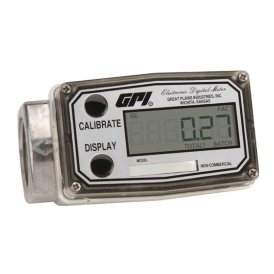
Electronic digital meter
Hide thumbs
Also See for 03 Series:
- Product owners manual (28 pages) ,
- Product owners manual (28 pages)

Related Manuals for GPI 03 Series


Summary of Contents for GPI 03 Series
- Page 1 SAVE THESE INSTRUCTIONS 03 Series ELECTRONIC DIGITAL METER Owner’s Manual 11/02/2020 920685-09 Rev M...
-
Page 2: Table Of Contents
This symbol is used through- out the manual to call your This manual will assist you in operat- attention to safety messages. ing and maintaining your 03 Series W a r n i n g s WARNING meter. Differences in models are... -
Page 3: Introduction
Care must be taken into account during installation and use to prevent impact or friction. INTRODUCTION WARNING Your GPI Electronic Digital Meter Part of the enclosure is con- is designed for measuring liquids. structed from plastic. To prevent The meter translates pulse data... - Page 4 Quick Start CAUTION If your installation is rela tively simple Make sure the thread tape or and you have installed our Electronic sealing compound does not Digital Meter (EDM) meters before, interfere with flow. you may use this section to quickly install and operate your meter.
-
Page 5: Meter Installation
4. To ensure accurate measure- INSTALLATION ment, remove all air from the system before use. To purge the Review the Before Installation and system of air: Quick Start Sections. Also consider a. Open the discharge valve or the following recommen dations, es- nozzle and allow fluid to com- pecially if you are installing your meter pletely fill the system. -
Page 6: Meter Maintenance
Foreign material in liquid can clog the 3. If the meter is not immediately meter’s rotor. If the problem affects installed again, cap the hose end meter accuracy or material coats or pipe to prevent spills. the rotor, install screens to filter the To Clean incoming flow. -
Page 7: Troubleshooting
TROUBLESHOOTING SYMPTOM PROBABLE CAUSE CORRECTIVE ACTION A. METER IS NOT 1. Field Calibration not Field calibrate again or select ACCURATE performed properly Factory Calibration. 2. Factory Calibration Perform a Field Calibration not suitable for liquid according to Calibration Section. being measured 3. -
Page 8: Meter Specifications
TROUBLESHOOTING (CONTINUED) SYMPTOM PROBABLE CAUSE CORRECTIVE ACTION D. REDUCED 1. Meter clogged with Remove meter. Clean carefully with FLOWRATE & dried liquids WD-40 or similar penetrating lubri- ® METER DOES cant. Make sure rotor spins freely. NOT COUNT E. CANNOT GET 1. - Page 9 The following specifications are dependent upon housing materials. Pressure Rating: Aluminum: 300 PSIG (20.7 bar) Nylon: 150 PSIG (10.3 bar) Recommended Chemicals: Aluminum Models: Are recommended for use with petroleum products, and should not be used with water. Please verify chemical compatibility with all wetted parts.
-
Page 10: Q9 Specifications
MECHANICAL Housing Transparent Amorphous Nylon Material +0°F to +129°F (-18°C to +54°C) Operating If wider operating temperature ranges are desired, Temperature reference information on GPI Remote Kits. ® Storage -40°F to +158°F (-40°C to +70°C) Temperature ELECTRICAL Input Minimum Pulse In:... - Page 11 SPECIFICATIONS (CONTINUED) DIMENSIONS Length Height Height (Mounted) Width (Widest Point) “A” “B” “C” “D” 3.40 in. 0.85 in. 0.72 in. 2.14 in. (8.6 cm) (2.1 cm) (1.8 cm) (5.4 cm) Figure 4 COMPUTER DISPLAY FEATURES FLOATING DECIMAL FACTORY CALIBRATION POINT (3 PLACE) INDICATOR BATCH TOTAL OR CALIBRATE...
- Page 12 If one component has no ratings, the resultant combination has no ratings. Specific Conditions of Use 1. All computer assemblies are to be used with GPI battery 902004-02 except Q1, Q9, and R9 versions which use Energizer E92 / EN92, or Duracell MN2400 Alkaline batteries.
-
Page 13: Q9 Installation
® designed to work with several the two buttons on the front panel. accessory output modules. In a GPI turbine meter, liquid flows The CMOS, microprocessor-based through the turbine housing causing electronics have extremely low an internal rotor to spin. As the... -
Page 14: Q9 Operation
OPERATION COMPUTER DISPLAY All operations are revealed on the Push button operation varies LCD using the large 6-characters in dependent upon the various modes the top row and smaller characters of operation, i.e. Normal Operation and symbols in the second row. mode and Field Calibration mode. - Page 15 OPERATION NORMAL OPERATION MODE Button Usage Map - Normal Operation Mode BUTTON Batch Total Display Toggles Between Accumulative Total Hold for 3 Seconds When Batch Total Display to Reset Batch Total is Displayed Gallons Hold Press Toggles Between Calibrate Display Litres Hold for 3 Seconds to Enter Calibrate...
- Page 16 OPERATION (CONTINUED) NORMAL OPERATION MODE (CONTINUED) Display Button: Batch total reset When a batch total (see Figure a three second count down, then 10-1) is displayed, press and reset the batch total to zero. (See continue to hold Display button for Figures 10-2 thru 10-4) 3 seconds;...
-
Page 17: Q9 Calibration
OPERATION (CONTINUED) FIELD CALIBRATION MODE (CONTINUED) Field Calibration Method General The field calibration method may be with fluids other than set by the user, and can be changed mentioned above. or modified at any time using a field For improved accuracy under such calibration method described in this conditions, the computer allows for section. - Page 18 OPERATION (CONTINUED) FIELD CALIBRATION MODE (CONTINUED) Field Calibration Method At the beginning of the calibration The bottom row of characters will be method entry menu, the software will in focus to indicate that the user can allow the user to start the calibration select between either “Start”...
- Page 19 OPERATION (CONTINUED) FIELD CALIBRATION MODE (CONTINUED) Begin dispensing into a container of known accurate volume. As soon as pulses are detected by the software, the screen will switch to display the volume being dispensed on the top row and the volume unit on the bottom row. (See Figure 12-2) Figure 12-2 When the user is finished with the...
-
Page 20: Q9 Maintenance
AAA size batteries (1.5-volts To maintain the Agency Approvals each) installed. The installed batteries of this device, and maintain the GPI are Agency Approval rated for use warranty, the batteries listed below with this electronic device. -
Page 21: Parts
OPERATION (CONTINUED) COMPUTER MAINTENANCE (CONTINUED) When batteries are disconnected or fail, It is strongly recommended that battery the computer memory will retain the checks and terminal cleaning be a part batch total, accumulative total, factory of a routine maintenance schedule. calibration curve, and field calibration Battery terminals should be cleaned curve indefinitely. -
Page 22: Service
Intrinsically Safe for Class I, II, III, Division 1, All Groups Intrinsically Safe approval only applies when used with ® FM Approved meter Q9 Computer Electronics when installed on a GPI Fm Approved meter ATEX Factory Mutual Approved IP65 Intrinsically Safe for Class I, II, III, Division 1, All Groups... -
Page 23: Declaration Of Conformity
Declaration of Conformity We declare, that the product: Product Name: Electronic Digital Meter Model Numbers: 03***** A1*********** A2*********** G2*****9*** Model numbers include all combinations of an alpha-numeric series as illustrated above. Conforms with the requirements of the Directives below by compliance with the Standards subsequently listed: Council Directive 2004/108/EC (until April 19, 2016) and Directive 2014/30/EU (from April 20, 2016) relating to Electro-Magnetic Compatibility. -
Page 24: Warranty
To make a claim against this warranty, contact the GPI Customer Service Department at 316-686-7361 or 888-996-3837. Or by mail at: Great Plains Industries, Inc.
Need help?
Do you have a question about the 03 Series and is the answer not in the manual?
Questions and answers