
Related Manuals for Walther Systemtechnik WLVCM


Summary of Contents for Walther Systemtechnik WLVCM
- Page 1 Walther Logic Valve Controller Mini (WLVCM) Article Number: 50008746 Operating Manual Edition Rev A...
- Page 2 Walther Systemtechnik GmbH Hockenheimer Straße 3 D-76726 Germersheim Germany Phone: +49 (0)7274-7022-0 Fax: +49 (0)7274-7022-91 info@walther-systemtechnik.com http://www.walther-systemtechnik.com Operating Manual WLVCM-BA-10 Page 2 of 37...
-
Page 3: Table Of Contents
WLVCM Overall System ........................20 Software Installation......................21 Start of Operation and Parametering ................... 22 Connecting to the Computer ........................ 22 Configuration Tool WLVCM – Overview ....................22 Configuration Tool WLVCM – Area USB Configuration ............... 23 Operating Manual WLVCM-BA-10 Page 3 of 37... - Page 4 Configuration Tool WLVCM – Area Configuration WLVCM ..............24 8.4.1 Heating Parameters ............................. 24 8.4.2 Application Parameters - Overview ......................25 8.4.3 Opening and Closing Times .......................... 26 8.4.4 Operating Mode “Series Shot“ ........................27 8.4.5 Operating Mode „Sequence Shot“ ......................28 8.4.6...
-
Page 5: Introduction
General Information This operating manual is provided for a safe operation of the “Walther Logic Valve Controller Mini“ (WLVCM). It contains safety instructions which must be strictly followed. This documentation gives you an overview of function and provides information on: •... -
Page 6: Warranty And Liability
Systemtechnik GmbH has a guarantee of 12 months under normal European operating conditions on its own parts (spare parts are excluded); or according to the conditions of the manufacturer. This guarantee can only be granted by Walther Systemtechnik GmbH, if: • the user has thorough knowledge of the content of this operating manual;... -
Page 7: Order Key
Order key WLVCM Software status Software Firmware status Hardware status Walther Logic Valve Controller Order key example: WLVCM-10-101-SOFT-101 Nomenclature Grundtyp WLVCM Walther Logic Valve Controller MINI Hardware status Version 1.0 Firmware status Version 1.0.1 Software Software included Software status Version 1.0.1... -
Page 8: Eu Declaration Of Conformity
• DIN EN ISO 12100 Safety of machinery - General principles for design - Risk assessment and risk reduction (ISO 12100:2010) Stefan Hirl, Hockenheimer Straße 3, D-76726 Germersheim Germersheim, 08.06.2018 (place, date) (Stefan Hirl, Management Board) Operating Manual WLVCM-BA-10 Page 8 of 37... -
Page 9: Safety
No changes will be made at the device. The customer carries the sole responsibility for consequences resulting from failure to observe this guideline. Please contact Walther Systemtechnik GmbH for any desired modifications. Make sure that the device is always in a safe operational condition. Checks for proper function or damages have to be performed by specialists on a regular basis. -
Page 10: Correct Use
In addition, it is essential that the operating personnel are familiar with the contents of the operating instructions supplied.Observing and following all instructions of this manual. • The WLVCM can only be used as built-in device in a switch cabinet. • Performing the inspection and routine maintenance tasks. Incorrect Use... -
Page 11: Qualification Of Personnel And Personal Protective Equipment
CAUTION Danger through improper use • The WLVCM can cause hazards if it is used by untrained personnel inappropriately or for purposes other than its intended use. • In all phases of life, work may only be carried out by trained and instructed personnel. -
Page 12: Transport
Transport Packaging The device will be prepared by Walther Systemtechnik GmbH for a transport to the first destination. The type of packaging depends on the individual mode of shipping. If not separately contracted, the packaging is in accordance with the rules and regulations of Walther Systemtechnik GmbH. This rule is in accordance with the Federal Association for Packaging HPE. -
Page 13: Description Of The Product
Description of the Product General Information The Walther Logic Valve Controller Mini (WLVCM) is a digital real-time control unit for the direct operation of electro-pneumatic spray, dosing or pulse valves from Walther Systemtechnik GmbH. Above that, the WLVCM allows the operation of hotplates from Walther Systemtechnik GmbH which can be optionally added to the employed spray, dosing or pulse valves. -
Page 14: Mechanical Installation
The WLVCM comes with a fixing unit on the back for mounting on DIN profiled rails. The WLVCM will be horizontally installed on the profiled rail using the fixing unit. Please refer to the below figure 1 for the dimensions which have to be considered. -
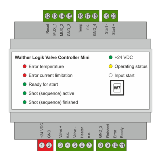
Page 15: Electrical Installation
Besides the function-relevant electrical interfaces W1 to W7 (see also chapter 6.2.1), the WLVCM also has an optical interface O1 which consists of eight LEDs and displays the current system status on the front of the WLVCM for the user (see also chapter 6.2.2). Figure 2 gives you an overview of these interfaces. - Page 16 6.2.1.1 Interface W1 „Supply Voltage“ A 24 V voltage source is required for operating the WLVCM and its electronics. It will be connected to the clamps +24 V and 0 V at the electrical interface „W1“.
- Page 17 The electrical interface W3 has three digital outlet clamps which are described below and which are used to display the current status of the WLVCM (see also table 4). Each of the clamps at Pins 9, 10 and 11 indicates its status through the two signal levels LOW and HIGH. When signal level LOW is shown, the measurable voltage at the clamp is 0 VDC.
- Page 18 6.2.1.7 Interface W7 „USB“ Parametering the WLVCM will be made through the USB interface. Use it to connect the WLVCM to a Windows-PC where you can run the configuration tool WLVCM. You will need a USB cable with a Type B plug for connecting to the WLVCM.
-
Page 19: Optical Interface O1
Application not finished Operating voltage 24VDC available +24V No / wrong operating voltage available Active date transfer between WLVCM and configuration tool Operating status No active data transfer between WLVCM and configuration tool Start signal applied (clamps „Start –„ and „Start +“) -
Page 20: Wlvcm Overall System
A Windows PC with USB connecting cable is required for parametering. Power Pack Higher-level PLC WLVCM Windows-PC Electro-pneumatic spray, dosing or pulse valve with coil cable Compatible Heating plate (optional) Figure 5 – Components of a WLVCM overall system Operating Manual WLVCM-BA-10 Page 20 of 37... -
Page 21: Software Installation
Figure 6 – Installation assistant for installing the WLVCM configuration tool Installing the WLVCM configuration tool will be automatically followed by the installation of the USB driver (FTDI CDM Drivers / install_driver.exe) which is required for the communication between the WLVCM and your Windows operating system. -
Page 22: Start Of Operation And Parametering
When you have successfully installed the WLVCM and the configuration tool WLVCM, you can now connect the WLVCM to your Windows PC via a suitable USB cable. Then start the configuration tool WLVCM. Figure 6 shows you the user surface which will appear next and which is explained in detail in chapter 8.2. -
Page 23: Configuration Tool Wlvcm - Area Usb Configuration
COM interface in the drop-down list. The field “selected” ➂ will always show the interface of the WLVCM module with which a connection has been established. -
Page 24: Configuration Tool Wlvcm - Area Configuration Wlvcm
After an activation of the heating function through button ➀, the WLVCM will try to reach the preset required temperature. When you turn the heating ➀ off, this will also cut off the power supply to the connected hotplate, and it will cool down to the existing room temperature. -
Page 25: Application Parameters - Overview
If the field “actual temperature“ ➂ does not display any temperature, the heating is not or not properly connected to the WLVCM module. Use the heating control parameters ➃ for setting the PID heating control characteristics. Usually they come as defaults from the factory and are set in such a way that the actual temperature is adjusted to the required temperature with highest precision. -
Page 26: Opening And Closing Times
“series shot“ (see chapter 8.4.4) and “sequence shot“ (see chapter 8.4.5). Both chapters below will describe in detail these operating modes, based upon the sample configuration of opening and closing times from figure 11. Figure 12 – Sample series of opening and closing times Operating Manual WLVCM-BA-10 Page 26 of 37... -
Page 27: Operating Mode "Series Shot
Figure 12 gives you a sample configuration of a series shot. Both selected series shot parameters come with the depicted series of opening and closing times in the same figure. Figure 13 – Example for configuring a series shot based upon preset opening and closing times Operating Manual WLVCM-BA-10 Page 27 of 37... -
Page 28: Operating Mode „Sequence Shot
For carrying out the operation mode “continuity shot“ no parameters are required. When the continuity shot is performed, the connected spray, pulse or dosing valve will be opened/activated as long as the shot is performed. It will be closed/deactivated when the continuity shot is finished. Operating Manual WLVCM-BA-10 Page 28 of 37... -
Page 29: Start Parameters
The start parameters in subsection ➄ (see also figure 10) help you to configure the operation mode; the mode will be carried out when the WLVCM receives a respective start signal – the so-called trigger – at the clamps („Start -“ and „Start +“), (see also chapter 6.2.1.6). The following configuration options are available for the parameters “Trigger“... -
Page 30: Loading / Saving
WLVCM, or you can save these on a data carrier (see also chapter 8.5.1). On the other hand, you can also test previously selected application parameters (see also chapter 8.5.2). Please use the buttons “loading/saving“... -
Page 31: Test Of Parameters
Once a set of parameters was read from or transferred into the WLVCM, the currentness of each parameter – for heating as well as for application parameters – will be indicated by the symbol to the left. If you make changes to the parameters in the configuration tool WLVCM, the parameter group which you change will delete the symbol. -
Page 32: Sample Signal Curves For Communication With A Superordinate Control Unit
“Ready” = HIGH. Figure 18 – Signal curve for carrying out an application cycle which was triggered by a single pulse; digital inlet signal “Start“ is applied beyond the duration of the application. Operating Manual WLVCM-BA-10 Page 32 of 37... - Page 33 “Finished” will follow directly after the digital inlet signal with inverted signal level. Figure 20 – Signal curve for the performance of an application cycle which is triggered by a permanent signal Operating Manual WLVCM-BA-10 Page 33 of 37...
- Page 34 Figure 20 shows you an example of an error which is indicated by an applied digital outlet signal „Error“ = HIGH. As long as the digital outlet signal “Error” = HIGH is applied, the WLVCM is not ready for operation and the digital outlet signal “Ready” will be automatically switched to LOW. During this time no application can be started (see also figure 20).
-
Page 35: Service, Maintenance, Troubleshooting
10.2 Troubleshooting IMPORTANT First check if all supply lines are properly connected and functioning. In case of serious problems that cannot be resolved, please contact the Walther Systemtechnik GmbH customer service. Customer Service / Support 10.3 Walther Systemtechnik GmbH Hockenheimer Straße 3... -
Page 36: Spare Parts/Accessories
All available spare parts are listed in the following table. Article number Description 50008747 WLVCM-10-101 – Walther Logic Ventilsteuerung MINI 50008745 SOFT-WLVCM-101-U – Software WLVCM Table 11 – Spare parts/accessories Operating Manual WLVCM-BA-10 Page 36 of 37... - Page 37 Article Number WLVCM-BA-10...
Need help?
Do you have a question about the WLVCM and is the answer not in the manual?
Questions and answers