Table of Contents
Advertisement
Quick Links
Rev. 1.3
Assembly Instructions
Spray Valve SMS-05
Article Number:
NOTE
Please read the Assembly Instructions carefully before first using the incomplete device and
strictly adhere to the instructions!
The incomplete device may only be worked with and worked on by persons who are familiar
with the assembly instructions and the current regulations for industrial safety and accident
prevention.
Always keep this translated version of the "Original Assembly Instructions" at the incomplete
Assembly Instructions – Spray Valve SMS-05
S05-....
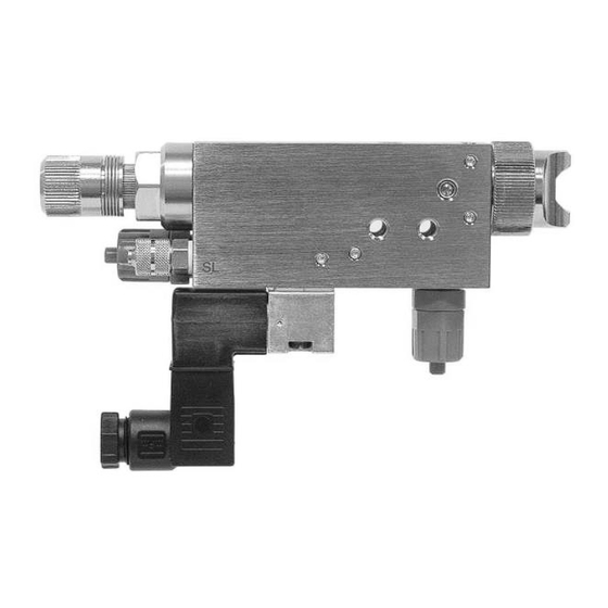
Figure: Spray Valve SMS-05 with flat-jet air cap and raster needle lock
device! The instructions have to be available anytime!
Walther Systemtechnik GmbH – D 76726 Germersheim
Telefon: +49 (0)7274-7022-0 Telefax: +49 (0)7274-7022-91
http://www.walther-2000.de – info@walther-2000.de
Page 1 of 31
Advertisement
Table of Contents

Related Manuals for Walther Systemtechnik SMS-05


Summary of Contents for Walther Systemtechnik SMS-05
- Page 1 Assembly Instructions Spray Valve SMS-05 Article Number: S05-…. Figure: Spray Valve SMS-05 with flat-jet air cap and raster needle lock NOTE Please read the Assembly Instructions carefully before first using the incomplete device and strictly adhere to the instructions! The incomplete device may only be worked with and worked on by persons who are familiar with the assembly instructions and the current regulations for industrial safety and accident prevention.
-
Page 2: Table Of Contents
Assembly Instructions – Spray Valve SMS-05 Rev. 1.3 Page 2 of 31 Table of Contents Page EC DECLARATION OF INCORPORATION ........................4 INTRODUCTION ..............................5 ......................5 ARGET ROUP OF THE SSEMBLY NSTRUCTIONS ............................5 IST OF IGNS AND YMBOLS SAFETY................................ - Page 3 Assembly Instructions – Spray Valve SMS-05 Rev. 1.3 Page 3 of 31 APPENDIX ................................ 19 10.1 SMS-05 ........................19 IMENSIONED RAWING 10.1.1 Spare Part Drawing SMS-05 ......................... 20 10.1.2 Spare Part Liste SMS-05 ........................21 10.2 .......................... 22 RTICLE UMBERS FOR 10.3...
-
Page 4: Ec Declaration Of Incorporation
Assembly Instructions – Spray Valve SMS-05 Rev. 1.3 Page 4 of 31 EC Declaration of Incorporation in accordance with EU Machinery Directive 2006/42/EU, dated 17 May 2006, Appendix II B We herewith confirm that the below mentioned incomplete device meets the basic requirements for safety and health as stated in EU Machinery Directive 2006/42/EU for its design and construction as well as for the configuration released by us on the market. -
Page 5: Introduction
GmbH has a guarantee of 12 months under normal European operating conditions on its own parts (spare parts are excluded); or according to the conditions of the manufacturer. This guarantee can only be granted by Walther Systemtechnik GmbH, if: ... -
Page 6: Correct Use
Assembly Instructions – Spray Valve SMS-05 Rev. 1.3 Page 6 of 31 2.4 Correct Use This device is a needle valve and will be used for processing materials which can be sprayed in continuous or intermitting operation. Under no circumstances shall aggressive media such as acids, alkaline solutions, detergents, chemicals or others be sprayed. -
Page 7: Transport
4.1 Designated Purpose The spray valves of SMS-05 series are suitable for the application of liquid up to viscous media, such as grease, oil, separating agents, colors or glues. One of the major characteristics of the SMS-05 series is the stepless adjusting of the spraying width as well as the integrated control valve for pre air and purging air. -
Page 8: Technical Data
Assembly Instructions – Spray Valve SMS-05 Rev. 1.3 Page 8 of 31 4.2 Technical Data General Data ca.126 x 22 x 82.5 with air cap – round jet Dimensions [mm] ca.129 x 22 x 82.5 with air cap – flat je Weight [g] ca. -
Page 9: Total View / Description
Assembly Instructions – Spray Valve SMS-05 Rev. 1.3 Page 9 of 31 5.2 Total View / Description Basic casing Nozzle with air cap and retainer ring Raster needle lock 3/2-way solenoid valve Material connection Atomizer air connection Control air connection 2x fastening thread M5 5.3 Adjusting the Device... -
Page 10: Sms-05 With Raster Needle Sensor
Assembly Instructions – Spray Valve SMS-05 Rev. 1.3 Page 10 of 31 SMS-05 with Raster Needle Sensor Optionally, you can use a raster-needle lock with a pre-installed, inductive proximity switch. It will release a signal when the needle piston with the needle is open. This will help you in digitally monitoring the status „nozzle open“. -
Page 11: Installation Diagram For Color Marking Systems
The SMS-05 Spraying Valve usually works with a control air pressure of 4.5 – 6 bar. The atomizing air pressure must be less than the material pressure, in order to prevent a backflow of the material. Atomizer air and material pressure have to be closely correlated. -
Page 12: Operating Elements
Assembly Instructions – Spray Valve SMS-05 Rev. 1.3 Page 12 of 31 If the pause time is a multiple of the spraying time, the valve must be operated several times in order to optimize the application process. Alternatively a free-spraying can be performed in a separate posi- tion. -
Page 13: Maintenance And Repair
7 Maintenance and Repair 7.1 General Information The spraying valves of the SMS-05 series are high precision tools. Always keep clean and observe minimum instructions to maintain a long and useful life of valve. We recommend lubricating moveable parts regularly, and greasing threads, especially the nozzle threads, when replacing or cleaning the nozzle. -
Page 14: Replacing Nozzle And Needle
Assembly Instructions – Spray Valve SMS-05 Rev. 1.3 Page 14 of 31 Replacing Nozzle and Needle Loosen retainer ring (1) and remove air cap (2). Unscrew raster lock (8) and remove. (Caution: there is spring pressure in the lock) ... -
Page 15: Maintenance For Use In Color Marking Systems (Normal Operation)
Assembly Instructions – Spray Valve SMS-05 Rev. 1.3 Page 15 of 31 The same procedure applies when replacing the sealing elements of the air valve. IMPORTANT O-rings and sealings screws are sensitive parts, too, and can be damaged. Do not use any sharp or pointed metallic implements for inserting the sealings The sealing screw in particular is a high-precision part with excellent sealing characteristics which should not be exposed to impulses or pressures. -
Page 16: Spare Parts
8 Troubleshooting 8.1 General Information IMPORTANT First check all supply lines for proper connection and serviceability. In case of serious problems that cannot be resolved, please contact the Walther Systemtechnik GmbH customer service. 8.2 Malfunctions: Fault Possible Cause Action... -
Page 17: Spray Image / Type Of Defect
Assembly Instructions – Spray Valve SMS-05 Rev. 1.3 Page 17 of 31 8.3 Spray Image / Type of Defect SPRAY IMAGE PROBLEM CAUSE ACTION Normal Spray Image (Flat jet) Normal Spray Image (Round jet) Spray image shaped Spray image shaped... -
Page 18: Taking Out Of Service
Assembly Instructions – Spray Valve SMS-05 Rev. 1.3 Page 18 of 31 9 Taking out of Service 9.1 Short Interruption A short interruption (15 min or more) has to be followed by a clean spraying. IMPORTANT Please follow the operating instructions! 9.2 Long-term Interruption... -
Page 19: Appendix
Assembly Instructions – Spray Valve SMS-05 Rev. 1.3 Page 19 of 31 10 Appendix 10.1 Dimensioned Drawing SMS-05 Walther Systemtechnik GmbH – D 76726 Germersheim Telefon: +49 (0)7274-7022-0 Telefax: +49 (0)7274-7022-91 http://www.walther-2000.de – info@walther-2000.de... -
Page 20: Spare Part Drawing Sms-05
Assembly Instructions – Spray Valve SMS-05 Rev. 1.3 Page 20 of 31 10.1.1 Spare Part Drawing SMS-05 IMPORTANT If the spraying valve is equipped with a nozzle prolongation, the nozzle (3) and the nozzle needle (7) are special versions. Therefore, when ordering spare parts the article numbers for the nozzle and the nozzle nee- dle must be inquired separately. -
Page 21: Spare Part Liste Sms-05
Assembly Instructions – Spray Valve SMS-05 Rev. 1.3 Page 21 of 31 10.1.2 Spare Part Liste SMS-05 Dwg.-No. Article No. Description 97410028 Retainer ring Air cap flat-jet/round jet Ø20 x 14.5mm Nozzle, stainless steel, Ø 12 x 18mm, SW7 97510713... -
Page 22: Article Numbers For Air Caps
Assembly Instructions – Spray Valve SMS-05 Rev. 1.3 Page 22 of 31 10.2 Article Numbers for Air Caps Air cap, Flat-jet, Standard, 60° (Ø20x14.5mm) Artikel-Nr. Description 97310234 Air cap, Flat-jet, 0.2-1.0mm 97310235 Air cap, Flat-jet, 1.2-1.5mm 97310236 Air cap, Flat-jet, 1.8-2.0mm 97310237 Air cap, Flat-jet, 2.5mm... -
Page 23: Article Numbers For Nozzles
Assembly Instructions – Spray Valve SMS-05 Rev. 1.3 Page 23 of 31 10.3 Article Numbers for Nozzles Nozzle, Standard, stainless steel (Ø12x18mm) Artikel-Nr. Description 97210110 Nozzle, Standard, 0.2mm 97210111 Nozzle, Standard, 0.3mm 97210112 Nozzle, Standard, 0.5mm 97210113 Nozzle, Standard, 0.8mm 97210114 Nozzle, Standard, 1.0mm... -
Page 24: Article Numbers For Nozzle Needles
Assembly Instructions – Spray Valve SMS-05 Rev. 1.3 Page 24 of 31 Marking nozzle, stainless steel 8°(Ø8x18mm) Artikel-Nr. Description 97212055 Marking nozzle 0.2mm 97211875 Marking nozzle 0.3mm 97212025 Marking nozzle 0.4mm 97211461 Marking nozzle 0.5mm 97212146 Marking nozzle 0.8mm Nozzle, special spin, stainless steel (Ø12x18mm) Artikel-Nr. -
Page 25: Article Numbers For Valves
Assembly Instructions – Spray Valve SMS-05 Rev. 1.3 Page 25 of 31 10.5 Article Numbers for Valves 3/2-way Solenoid valve (complete with plug and 12.0 seal) Artikel-Nr. Description 97150104 Magnetic valve 24V / DC/2.5 W (with manual trigger) 97150017 Magnetic valve 110V/50Hz/1.5W 97150016 Magnetic valve 220V/50Hz/1.5W... -
Page 26: Wear-And-Tear Parts
Assembly Instructions – Spray Valve SMS-05 Rev. 1.3 Page 26 of 31 Screwed joint for connection „Material circulation 15.2 (Option 2)“ Artikel-Nr. Description 97220089 L-plug-in Screwed joint QSL M5 - 6/4 97220573 L-plug-in Screwed joint QSL M5 - 6/4 97220551... -
Page 27: Accessories
Assembly Instructions – Spray Valve SMS-05 Rev. 1.3 Page 27 of 31 10.8 Accessories Figure Article Number Description Nozzle extension 97xxxxxx (see product catalog ACCESSORIES) 97410042 Retainer ring hexagonal 97410059 Retainer ring stainless steel Heating plate 979565.002 (see product catalog ACCESSORIES) -
Page 28: Center Hole For Centering Sleeve 97320602
Assembly Instructions – Spray Valve SMS-05 Rev. 1.3 Page 28 of 31 Figure Article Number Description 97320602 Centering sleeve for an exact positioning of the valve 10.8.1 Center hole for Centering sleeve 97320602 WICHTIG If a Centering sleeve is retrofitted to an existing valve, the valve must be returned to us for retrofitting of Center hole Walther Systemtechnik GmbH –... -
Page 29: Add-On Elements
Assembly Instructions – Spray Valve SMS-05 Rev. 1.3 Page 29 of 31 10.8.2 Add-on Elements Needle Sensor The mounting of the needle sensor will be made factory-side. It will be integrated in the raster needle lock (Pos. 15.4 Spare Part List). If ordered as spare part, please note that a complete raster needle lock will be delivered as the initiator has to be set at the factory and also glued in. -
Page 30: Description Of Pneumatic Needle-Stroke Adjustment 978000037
Assembly Instructions – Spray Valve SMS-05 Rev. 1.3 Page 30 of 31 10.8.3 Description of Pneumatic Needle-Stroke Adjustment 97800037 Description of Function The pneumatic Needle Stroke Adjustment (PNA) is used for a remote-controlled change between two nee- dle-stroke settings. The front regulating screw (1; see pic.) determines the minimum needle stroke of the spraying device for a PNA with applied pressure. - Page 31 Assembly Instructions – Spray Valve SMS-05 Rev. 1.3 Page 31 of 31 Pos. Article No. Description 97610172 Raster head 97610170 Regulating hollow spindle 97820000 Pressure spring 97320022 Cylinder pin DIN 6325 97320196 Regulating button 97710021 Piston complete 97320145 Piston rod...
Need help?
Do you have a question about the SMS-05 and is the answer not in the manual?
Questions and answers