Table of Contents
Advertisement
Quick Links
Advertisement
Table of Contents

Subscribe to Our Youtube Channel
Related Manuals for Xylem TitroLine 7800


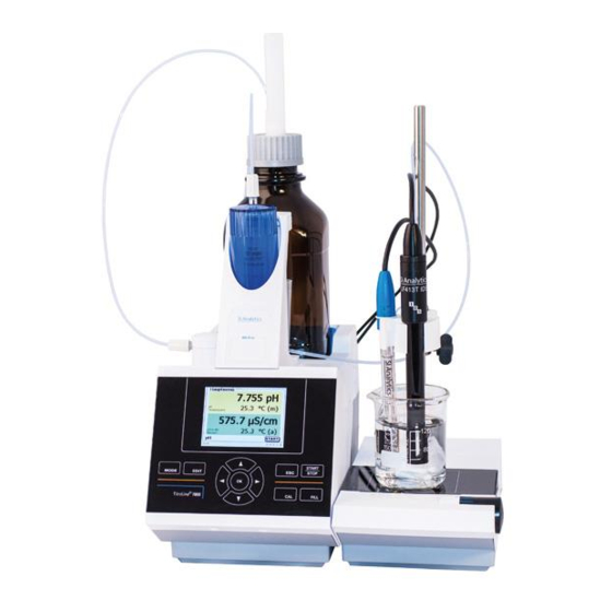
Summary of Contents for Xylem TitroLine 7800
- Page 2 Gebrauchsanleitung ....................Seite 3 … 146 Wichtige Hinweise: Die Gebrauchsanleitung ist Bestandteil des Produktes. Vor der ersten Inbetriebnahme bitte sorgfältig lesen, beachten und anschließend aufbewahren. Aus Sicherheitsgründen darf das Produkt ausschließlich für die beschriebenen Zwecke eingesetzt werden. Bitte beachten Sie auch die Gebrauchsanleitungen für eventuell anzuschließende Geräte.
-
Page 3: Table Of Contents
TABLE OF CONTENT ® Technical Specifications of the Titrator TitroLine 7800 ........149 Notes to the operating manual ....................149 Intended Use ......................... 149 Technical Specifications ......................150 ® 1.3.1 Titrator TitroLine 7800 ......................150 1.3.2 Titrationstand TM 235 KF ...................... 153 Warning and safety information .................... - Page 4 11 Guarantee ......................290 12 Storage and transportation ................. 290 13 Recycling and Disposal ..................290 Copyright © 2020, Xylem Analytics Germany GmbH Reprinting - even as excerpts - is only allowed with the explicit written authorization. Germany. Printed in Germany.
-
Page 5: Technical Specifications Of The Titrator Titroline 7800
® Technical Specifications of the Titrator TitroLine 7800 Notes to the operating manual The provided operating manual will allow you the proper and safe handling of the product. For maximum security, observe the safety and warning instructions in the operating manual! Warning of a general danger: Non-compliance results (can result) in injury or material damage. -
Page 6: Technical Specifications
Technical Specifications ® Titrator TitroLine 7800 1.3.1 Translation of the legally binding German version (Release: 16. August 2018) EMC compatibility according to the Council Directive: 2014/30/EU; applied harmonized standards: EN 61326-1: 2013 Low-voltage directive according to the Council Directive 2014/35/EU; Testing basis EN 61 010-1: 2010 for laboratory equipment RoHS Council Directive 2011/65/EU FCC Part 15B and ICES 003... - Page 7 ® Measuring input 2 (IDS Measurement input connector for intelligent digital sensors. Measurement Display Measurement accuracy* range resolution without sensor probe depending on sensor type 0.001 depending on sensor type depending on sensor type depending on sensor type Temperature °C depending on sensor type depending on sensor type Conductivity...
- Page 8 Stirrer/pump: 12V DC out, 500 mA power supply for stirrer TM 235 and KF titration stand TM 235 KF Housing: Material: Polypropylene Front keyboard: polyester coated Dimensions: 15.3 x 45 x 29.6 cm (W x H x D), height incl. interchangeable unit Weight: approx.
-
Page 9: Titrationstand Tm 235 Kf
Titrationstand TM 235 KF 1.3.2 Translation of the legally binding German version (Release: 16. August 2018) ® In connection with the titrator TitroLine 7800 EMC compatibility according to the Council Directive: 2014/30/EU; applied harmonized standards: EN 61326 Part 1: 2013 Low-voltage directive according to the Council Directive 2014/35/EU;... -
Page 10: Warning And Safety Information
Warning and safety information The device corresponds to protection class III III. It was manufactured and tested according to DIN EN 61 010, Part 1, "Protective Measures for electronic measurement devices" and control devices and has left the factory in an impeccable condition as concerns safety technology. -
Page 11: Installation And Commissioning
Installation and Commissioning Unpacking and setting up The device has been put together especially for you (basic unit + corresponding modules and accessories), there may be differences with respect to the delivery and the accessories described in this chapter. The scope of delivery, please refer to the attached packing list. -
Page 12: Back Panel Of The Titrator Titroline 7800
® Back panel of the titrator TitroLine 7800 Fig. 1 ® The TitroLine 7800 is equipped with the following connections: USB-B interface for connection to a PC On/Off switch Two USB-A (“Master”) interfaces for connecting USB devices Socket “in”: Connection of the external power supply TZ 1853 Socket “out”: Connection of the TM 235 / TM 235 KF magnetic stirrer Two RS232 ports, 4-channel (Mini-DIN): RS1 for connection to the PC... -
Page 13: Connection And Installation Of The Titrator And The Magnetic Stirrer Tm235/Tm235 Kf
Connection and installation of the titrator and the magnetic stirrer TM235/TM235 KF The low voltage cable of the power supply TZ 1853 has to be plugged in to the 12 V socket “in”, on the back panel of the titrator. (Fig. 2). Then plug the power supply into the plug socket. Fig. -
Page 14: Setting The Language
Setting the language The ex-factory default language setting is English. After the device is switched on and the start-up process is complete, the main menu appears (Fig. 6). Fig. 6 Using <SYS> or <MODE>, you navigate to the system settings («System settings »... -
Page 15: Connection And Installation Of The Tm 235 Kf Titration Stand And Titration Vessel
Connection and installation of the TM 235 KF titration stand and titration vessel Place the TM 235 KF titration stand to the right of the titrator and connect to the 12V out-socket in the rear panel of the piston burette by using the TZ 1577 connection cable. The stand rod is screwed into the thread of the TM 235 KF. - Page 16 The moisture bottle is connected to the right connector (view from above) of the TM 235 KF. The waste (clear) bottle is connected to the left connector. Fig. 11 The PTFE tube from the clear waste bottle is adjusted to the ground (tube 1) of the titration vessel. The PTFE tube from the solvent bottle (tube 2) is adjusted as shown in Fig.
- Page 17 The burette tip is placed into the left NS 14 opening and connected to the valve of the interchangeable unit. Put first some glass wool and then molecular sieve in the plastic moisture tube. Place it to the other NS 14 opening as shown in Fig.
-
Page 18: Exchangeable Head (Wa)
Exchangeable head (WA) Fig. 15 13) TZ 2003 - drying tube 14) TZ 3802 - threaded cap with borehole GL 45, incl. adapter with 2 openings for drying tube and suction hose 15) TZ 3873 - dosing hose without dosing tip and holding bracket, or TZ 3874 - dosing hose with dosing tip and holding bracket 16) TZ 3803 - 1 litre reagent bottle, brown 17) TZ 3900 - UV protection... -
Page 19: Placing And Replacing Of The Interchangeable Unit
Placing and Replacing of the Interchangeable Unit 2.7.2 The base unit comes with an RFID reader, and all the interchangeable units are equipped with an RFID transponder. This transponder can be used to store the following information: Unit size (cannot be changed) ... -
Page 20: Programming Of The Titration Unit
2.7.2.2 Replacing an Interchangeable Unit Removing the interchangeable unit is done in reverse order: Removing the interchangeable unit is only possible as long as the piston is in the lower position (zero position). Possibly, it may be necessary to press <FILL> first. Depress the black button on the left, and then pull the interchangeable unit forward (Fig. - Page 21 Following the optional input of additional parameter, press <ESC> to leave the reagents menu (Fig. 22). Important for KF: The approximate concentration of the KF titrant (e.g. 5 or 2) should be entered under «Concentration». Thereby the drift in µg/min can be calculated in the right dimensions. Fig.
-
Page 22: Initial Filling Or Rinsing Of The Entire Interchangeable Unit
Initial Filling or Rinsing of the Entire Interchangeable Unit 2.7.4 While the initial filling or rinsing programme is being run, please place a sufficiently dimensioned waste vessel under the titration tip. Initial filling of the interchangeable unit is done using the «rinsing» program. Fig. - Page 23 Initial filling requires a minimum of two rinsing cycles! Fig. 28 You can stop the rinsing operation (Fig. 29) at any time by pressing <STOP> and then resume rinsing with <START>. Fig. 29...
-
Page 24: Installing The Burette Tip
Installing the burette tip The burette tip consists of the elements shaft with threaded clamping joint, hose and slip-on tip (Fig. 30). stop ring marking hose shaft threaded clamping joint Fig. 30 Burette tip - Sequence of assembly: Cut of hose end evenly. Slip parts of the threaded clamping joint on to the hose. -
Page 25: Kf: Filling The Titration Vessel With Solvent
KF: Filling the titration vessel with solvent The solvent is pumped from the solvent bottle into the titration vessel by pushing down the front part of the rocker switch on the titration stand TM 235 KF. Pump solvent (approx. 35-40 ml) into the titration vessel until the titration tip and the electrode are completely immersed (Fig. - Page 26 Glass cylinder Piston rod Fig. 32 Piston rod Fig. 33 Fig. 34 The interchangeable unit and the cylinder size have to correspond. Otherwise the coding, which is memorized within the interchangeable unit will no longer match the cylinder size. This will trigger incorrect dosage. For the sake of dosing and analytical accuracy, it is also recommended to replace the PTFE piston each time a defective glass cylinder is replaced.
-
Page 27: Combination With Accessories And Additional Devices
2.11 Combination with Accessories and Additional Devices Connecting a printer 2.11.1 Printers with a USB interface are to be connected to one of the two USB-A interfaces. These printers have to feature HP PCL emulation (3, 3 enhanced, 5, 5e). So-called GDI printers cannot be used! Alternatively the thermo-compact printer Seiko S445 can be connected. - Page 28 If you connect the electrode, the electrode menu is automatically displayed with the characteristics of the electrode (such as name, batch number, etc.) for about 10 seconds (Fig. 36). Fig. 36 The display then switches to the normal display, showing in this case (Fig.
-
Page 29: Working With The Titrator Titroline 7800
® Working with the Titrator TitroLine 7800 Front Keyboard Fig. 39 Apart from alphanumeric input (a-z, A-Z, 0-9) and a few other functions, almost all functions can be performed using the front keyboard (Fig. 39). <Mode>: Methods selection, rinsing, system settings <EDIT>: Changing the current method, new method, copy and delete method <ESC>:... -
Page 30: Manual Controller
Manual controller The manual controller (Fig. 41) is needed for manual titration. It can also be used for starting dosage or other methods. Fig. 41 Mode Black key Grey Key Start of titration, single-step and Filling Manual titration continuous titration Stop of titration including evaluation Dosage through Dosage method Start dosage... -
Page 31: Menu Structure
Menu Structure The menu screens shown in this manual serve as an example and may differ from what you see! There are 5 selection menus: Start or main menu Method parameters Method selection CAL menu System settings. - Page 32 <MODE>/F6 leads you to the select method menu (Fig. 44). Fig. 44 Existing methods can be selected by pressing <↓> and <↑> and confirming the selection with <ENTER>/<OK>. Once the selection made, you will return to the main menu with the newly selected method. If no method is selected <ESC>...
-
Page 33: Main Menu
Main Menu After power-up, the main menu is always the first menu to appear. The method displayed will always be the last method that was used (Fig. 47). Fig. 47 Automatic Titration 3.6.1 The method being displayed can now be carried out immediately with <START>. Depending on the method settings, you will be prompted for the sample identification (Fig. - Page 34 In the case of an automatic acceptance of the balance data, the weighed-in quantities will be read in from a memory. If the memory does not contain any balance data, a message will appear (Fig. 50). Fig. 50 Pressing the Print key will transfer the balance data, too. Titration will then begin directly after the transfer of the balance data without any further confirmation being necessary.
-
Page 35: Calibration (Cal-Menü)
The result will be displayed at the end of the titration (Fig. 53). Fig. 53 <MODE> can be used to view the titration curve or further resuts (Fig. 54). The pH und mV titration curves will show the measurement curve (blue) and the 1 derivation (red). - Page 36 The titrator will ask you to rinse the electrode and immerse it successively into 2 or 3 buffers (Fig. 56). Fig. 56 The 1 buffer is started with <START>. The 2 and 3 buffers (optional) are to be started with <ENTER>/<OK>. During calibration (Fig.
- Page 37 Once calibration completed, the display will show the slope and the zero point of the electrode (Fig. 60). Fig. 60 The calibration values will be automatically printed or stored as a PDF file. <ESC> will take you back to the main menu. The current calibration values can be viewed at any time.
- Page 38 Is a digital pH electrode connected to the measuring input B and B is used in the method of measuring input for pH measurement (Fig. 63), has yet to select after calling the calibration routine, if a pH electrode to the ®...
-
Page 39: Manual Titration
Manual Titration 3.6.3 Manual titration is impossible without the manual controller. The mV or pH reading will be displayed (Fig. 65). The value can be selected in the menu item «Titration parameter». Fig. 65 <START> or pressing the black key on the manual controller will start the manual titration method. Following the input of the sample description and/or the weight/volume (optional - please compare also the explanations in ... - Page 40 These stages can also be changed during manual titration (Fig. 67). Fig. 67 Stage 5 corresponds to maximum titration speed. Speed is reduced by 50% each time. Example: WA 20 interchangeable unit Stage 5 100 % (ca. 40 ml/min) Stage 5 50 % (ca.
-
Page 41: Kf Titration
KF Titration 3.6.4 The method being displayed can now be carried out immediately with <START>. The preconditioning is run first. The solvent and the titration vessel contain moisture (water) that should not influence the calculation of the result. The conditioning is run automatically after pressing <START> (Fig. 69). The final conditions are the same as the conditions of the actual sample titration. - Page 42 After the sample or the standard is added, you must press <START> again. Depending on the method settings, you will be prompted for the sample identification (Fig. 72) and the weighed-in quantity (Fig. 73). You can use an external PC keyboard for entering a 20-digit alphanumeric sample ID. Fig.
- Page 43 Pressing the Print key will transfer the balance data, too. Titration will then begin directly after the transfer of the balance data without any further confirmation being necessary. The display shows either the use in ml with the drift in µg/min (Fig. 75), ...
- Page 44 Scaling of the chart will be done automatically. The result will be displayed at the end of the titration (Fig. 78). Fig. 78 <MODE> can be used to view the titration curve or further results (Fig. 79). Fig. 79 If a printer is connected, the results will either be printed according to the settings made for the method, or else they will be memorised in the form of a PDF- and CSV-file file on a connected USB stick.
-
Page 45: Dosage
Dosage 3.6.5 3.6.5.1 Dosing operation with dosing method Use <START> or the black key of the manual controller to start a dosage method (Fig. 80 and Fig. 81). Fig. 80 Fig. 81 The dosed volume will be briefly displayed (Fig. 82) before the display returns to the main menu (Fig. 83). Fig. - Page 46 The next dosage operation can be started immediately. Filling of the unit will occur automatically. (This option can be switched off. Then the cylinder will be filled when the maximum cylinder volume is reached). The unit can be filled at any time using <FILL>. <ESC>...
-
Page 47: Preparing Solutions
Preparing Solutions 3.6.6 The so-called “Preparing solutions” method is a special dosing method. In this process, a solvent is dosed to a sample weight of a substance until the desired target concentration is reached (Fig. 87 and Fig. 89). Fig. 87 Fig. -
Page 48: Method Parameters
Method parameters From the main menu, <EDIT> will take you to the method parameters (Fig. 91). Fig. 91 Method editing and new method If you select «edit method» or «new method» you will be taken to the modification or new creation of a method. Selecting «new method»... -
Page 49: Default Method
Default method The «Default methods» item of the device contains a series of ready-made standard methods which can be conveniently selected (Fig. 93). Fig. 93 Once the selection made, you are directly prompted for the input of the method name (Fig. 94). Fig. -
Page 50: Delete Method
Delete Method In this function you will be prompted to know whether the current method is actually to be deleted (Fig. 96). You have to reply «Yes» in explicit terms and also confirm this reply with <ENTER>/<OK>. Fig. 96 Print method The currently selected method can be printed on a connected printer or stored on an USB drive as PDF file (Fig. -
Page 51: Change Method Parameters
Change Method Parameters The input or modification of the method name was already described in 4.1 and 4.3 Fig. 98 Method type 4.6.1 On the «Method type» you can select whether you wish to perform a manual or automatic titration, a dosage or whether you wish to prepare a solution. - Page 52 4.6.2.1 Linear titration In the case of linear titration, the step size remains identical over the entire titration cycle. Linear titration is often used for complicated or unknown samples. Complicated examples include, for instance, chloride in the trace range (-> very flat curve pattern) or titrations in non-aqueous media. If one would use a dynamic titration control in these cases, this would not yield any benefit.
- Page 53 4.6.2.3 End-Point titration The goal of End-Point titration consists in titrating as precisely as possible to an end point given in terms of pH, mV or µA. In the case of pH und mV you can also titrate to two end points. Consumption in the end point will be used as a result.
-
Page 54: Result
During the titration, the pH/time (Fig. 103) or the ml/time (Fig. 104) curve and the pH value/ml can be displayed analog. Fig. 103 Fig. 104 Result 4.6.3 At first, the calculation options (dynamic and linear titration only) are specified (Fig. 105). Fig. - Page 55 Up to 2 inflection points (2 EQs) can be analyzed (Fig. 106). Fig. 106 With «only total consumption» the consumption at the last measured pH/mV value will be used. With «1 EQ» respectively «2 EQ´s» the calculated equivalence points of the titration curve will be used. «Formula»...
- Page 56 4.6.3.1 Calculation Formula The appropriate calculation formula is selected on the «Formula selection» submenu (Fig. 109). Fig. 109 If two inflection points (2 EQs) are selected, formula 1, formula 2 and 3 can be selected (Fig. 110). Fig. 110 The calculation formula for the 2nd EQ is selected for the second formula (Fig. 111). Fig.
- Page 57 The following calculation formulae are available for EQ and EP: Formula for linear and dynamic Formula for titrations to Information titration to EQ1 End-Point (EP 1 and EP2) No formula No result will be determined. (EQ1-B)*T*M*F1/(W*F2) (EP1-B)*T*M*F1/(W*F2) Formula for calculating the concentration of a sample taking into account a blank value in terms of ml.
- Page 58 Formula for linear and dynamic Information titration to EQ2 Calculation of the consumption at EQ2 in ml (EQ2-B)*T*M*F1/(W*F2) Formula for calculating the concentration of a sample taking into account a blank value in terms of ml. Direct titration to EQ2 (ex.:phosphoric acid) (B–EQ2)*T*M*F1/(W*F2) Formula for calculating the concentration of a sample taking into account a blank...
- Page 59 The values for the blank value, the titers and factors F1 - F5 can be entered or read from a global memory (Fig. 112). Fig. 112 The values from the global memory were defined in advance by a titration or were manually entered (Fig. 113 and Fig.
- Page 60 The global memory used is displayed (Fig. 115). Fig. 115 Storing results in global memories is described in 4.6.3.7. The values of the individual parameters of the selected calculation formula, e.g. mol (Fig. 116), can now be input one by one. Fig.
- Page 61 Fig. 118 You have the following options: «Manual sample weight»: The sample weight is enquired by a prompt at the start of the method and manually input. «Automatic sample weight»: The sample weight is automatically transferred by a connected balance. ...
- Page 62 4.6.3.4 Formulae for the Preparation of Solutions A selection of special calculation formulae is available for the Prepare Solutions mode. The appropriate calculation formula is selected on the «Formula Selection» submenu (Fig. 121). Fig. 121 A selection of 3 different calculation formulae is available: W*(100-Fa-Fb)*Fc/Fd - W*(100-Fb)/(100*Fe) +Ff W*(100-Fa-Fb)*(Fd/Fg) - W*(100-Fb)/(100*Fg) +Ff W*(100-Fa-Fb)*Fc/(100*Fd)
- Page 63 4.6.3.5 Decimal digits To conclude, it is possible to determine the number of decimal digits from 0 - 6. The standard setting is 2 (Fig. 122). Fig. 122 4.6.3.6 Statistics The mean value and relative standard deviation can be automatically calculated and documented by using the statistics (Fig.
- Page 64 The mean value and relative standard deviation (RSD) are shown directly on the display (Fig. 125). Fig. 125 4.6.3.7 Global Memories Results of titrations can be written into one of the 50 global memories (M01 - M50) for additional calculations (Fig.
-
Page 65: Formula Editor
Example: The blank value of a chloride titration is defined with the support of an extra method. The result in ml is thereby automatically written into global memory M01 by using the name “Blanc value” (Fig. 128). The blank value is then automatically deducted from the titrant consumption within the chloride method. Fig. - Page 66 Confirm the selection «Result» with <ENTER>/<OK> (Fig. 131): Fig. 131 Select “Formula” with <ENTER>/<OK> (Fig. 132). Fig. 132 The following selection appears (Fig. 133). Fig. 133...
- Page 67 You can select the existing methods with <↓> and <↑> and confirm the selection with <ENTER>/<OK> (Fig. 134). Fig. 134 «Result text», «Select fomula», «Formula parameter», «Unit», «Decimal places», «Statistics» and «Global memory» don´t differ from previous versions. New is the menu item «Edit formula»! If you select «Edit formula»...
- Page 68 Fig. 137 Fig. 138 Instead of the formula character F1 you can now use e.g. directly enter a numeric value (Fig. 139). Fig. 139 The decimal point of the numeric value can be entered as a point or a comma. Press <ENTER>/<OK>...
- Page 69 4.6.4.2 Applicable Formula Characters, Arithmetic Operations and Values The following arithmetic operations can be used: Arithmetic operations Formula character Addition Subtraction Multiplication Division Calculations with brackets to 25 levels Logarithm to base 10 Exponential function The following formula characters are available: Formula characters...
- Page 70 4.6.4.3 Syntax check The syntax check is performed each time the formula is saved by the formula editor. It is checked, whether the number of opening brackets is equal to that of the closing ones. whether the entered variables and calculation operations are allowed. If an error occurs in the syntax, an error message is displayed (Fig.
-
Page 71: Titration Parameters
Titration parameters 4.6.5 The «Titration parameter» submenu is used to determine the actual parameters of the method (Fig. 143 and Fig. 144). Fig. 143 Fig. 144 4.6.5.1 Generally applicable titration parameters Depending on the titration mode (dynamic, linear, End-Point titration, Dead-Stop titration and pH-Stat titration), it is possible to enter a variety of parameters. - Page 72 The selected measured value is displayed for information (Fig. 146). Fig. 146 «Measuring speed» or drift will determine the span of time after which the measured value will be accepted following a titration step (Fig. 147). Fig. 147 Drift-controlled acceptance of the measured value in terms of mV/min is set by selecting «normal», «fast» or «user-defined»...
- Page 73 Fig. 148 If normal or fast drift was selected before, the values will be defaulted for user-defined drift. In the present case, for instance, 20 mV for normal drift: (Fig. 149). Fig. 149 Drift-controlled acceptance of the measured value is used in most applications. However, there are applications in which the setting of a fixed holding time for measured value acceptance following the titration step is recommendable.
- Page 74 After the start of titration, it makes frequently sense to have the sample stirred over a defined period of time, for instance, to allow for the sample to be dissolved. The waiting time to be observed prior to the first addition of titration solution can be set using the <Initial waiting time>...
- Page 75 The adjustable dynamics parameters can be selected (Fig. 153). Fig. 153 4.6.5.3 Attenuation setting The pH or mV signal becomes essentially quieter after a specific setting period when the attenuation is switched on («low», «medium» or «strong») (Fig. 154). Fig. 154 A minimum waiting period should therefore also be observed for the various attenuation settings.
- Page 76 4.6.5.4 Linear titration If linear titration control was selected, you have to define the step size (Fig. 155). Fig. 155 Linear step size can be set from 0.0005 to 5.000 ml (Fig. 156) Fig. 156 Linear step width can also be set for End-Point titration (pH, mV and dead stop). In this type of titration, linear step width is used after the first continuous titration stage.
- Page 77 4.6.5.6 Pretitration If the titration agent consumption is roughly known, you can set a pretitration volume. In this process, a defined volume is dosed (= pretitrated) following the initial waiting time. After the addition of the pretitration volume, another defined span of time is observed as the waiting time before the next titration step is added. The pretitration volume is automatically added to the titration agent consumption.
- Page 78 Fig. 160 Automatic detection of the equivalence point (EQ) can be switched on and off for linear or dynamic titration (Fig. 161). Fig. 161 If automatic EQ detection is off, titration will continue to the predefined end value in mV or pH or to the maximum ml value, respectively.
-
Page 79: End-Point Titration" And "Dead-Stop Titration" Titration Parameters
Setting of the «maximum titration volume» (Fig. 163) should always make sense. It also serves as a safety criteria to prevent excessive titration, i.e. a possible overflow of the titration vessel. The maximum titration volume can be set between 1.000 and 999.999 ml: Fig. -
Page 80: Titration Parameter Ph Stat Titration
Dead-Stop Titration and Polarization voltage Polarisation voltage in mV can only be set for Dead-Stop titration (Fig. 166). Fig. 166 The values can be set between 40 and 220 m. The pre-setting is 100 mV. Low polarisation voltage insensitive High polarisation voltage sensitive Titration parameter pH-Stat Titration 4.6.7... - Page 81 Depending on the application and duration, the time unit is defined in second, minute or hour (Fig. 169). Fig. 169 For example, measurements up to 2 hours can be entered in seconds (Fig. 170). Fig. 170 With a measuring interval of 60 seconds, that would be a total of 120 readings. Up to 1000 measuring points can be recorded for a pH-Stat titration (Fig.
- Page 82 Determination of Enzyme Activity The enzyme activity is a measurement of the number of substrate molecules, which converts an enzyme per second. The H ions produced during the reaction are thereby titrated with the NaOH solution. Then the slope formula is selected to calculate the slope in ml/s (Fig. 172). Fig.
- Page 83 Fig. 175 The start time always begins when the desired pH is reached. If, for example, the target pH is reached after 25 seconds, and the start time is 15 seconds, the evaluation begins at 40 seconds. Fig. 176...
-
Page 84: Dosing Parameter
Dosing parameter 4.6.8 The dosing parameters (dosing speed, filling speed and max. dosing/titration volume) are determined for each method. This applies to all types of methods such as manual and automatic titration, dosing and Solution Preparation (Fig. 177 and Fig. 178). Fig. -
Page 85: Sample Identification
The following filling options can be set for the dosing mode (Fig. 179): Fig. 179 «off» filling it will not occur automatically after each dosing step. «always» filling will occur automatically after each dosing step. «intelligent before» a verification will be performed each time prior to the next dosing step in order to determine whether the dosing step can still be made without a filling operation. -
Page 86: Documentation
Documentation 4.6.10 Three different format settings are available for documentation (Fig. 182) on a printer or USB device: «short», «standard (with curve) » and «GLP» (Fig. 183). Fig. 182 Fig. 183 Method type Short documentation Standard documentation GLP-documentation Same as ‘Short Same as ‘Standard Automatic Method name, date, time, duration of... -
Page 87: Method Parameters Of The Kf-Titration
Method parameters of the KF-Titration Standard methods of KF 4.7.1 If no titration has been performed yet, it is recommended to load one of the standard methods. These methods have default parameters and can generally be used immediately without changes. From the main menu, press <EDIT>... - Page 88 Standard methods KF Application Titer 1-Component (liquid standard) Determination of the concentration of the titration agent. Suitable for 1-component reagents.Standard is a liquid standard in ampoules with a concentration of 10 mg/g. Titer 1-Component (solid standard) Determination of the concentration of the titration agent. Suitable for 1-component reagents Standard is the standard substance sodium tartrat dihydrate with a water amount of 15.66 %.
- Page 89 Titration parameter Dead-Stop titration KF titration µA-Endpoint Delta µA-value Linear steps in ml Endpoint delay in s Delay time (between linear steps) Start delay time /extraction time Conditioning on/off ...
-
Page 90: Kf Titration Parameters
KF Titration parameters 4.7.2 The «Titration parameter» submenu is used to determine the actual parameters of the method (Fig. 187 and Fig. 188). The parameters were already introduced in 4.7. Fig. 187 Fig. 188 Generally applicable titration parameters Depending on the titration mode (KF or dead stop titration) it is possible to enter a variety of parameters. The following parameters are valid for the KF titration mode: ... - Page 91 4.7.2.1 Initial waiting time (Dead-Stop titration) / Extraction time (KF) With Dead-Stop titration, the «Initial waiting time» passes at the beginning of titration. In KF titration, the Initial waiting time = the «extraction time». The extraction time ends after the sample is supplied. The initial waiting/extraction time can be specified between 0 and 999 seconds (Fig.
- Page 92 4.7.2.4 Step size The «step size» can be set from 0.001 to 5.000 ml (Fig. 192). Typical values for the KF titration are 0.002 - 0.01 ml. Fig. 192 In this type of titration, linear step width is used after the continuous titration stage. 4.7.2.5 Pretitration If the titration agent consumption is roughly known, you can set a pretitration volume on the «Pretitration»...
- Page 93 4.7.2.7 Titration end The end of a titration (Fig. 195 and Fig. 196) is reached, and the result will be calculated as soon as, or if, respectively: The defined End value in µA value has been reached The Endpoint delay in seconds has been adhered ...
- Page 94 Maximum titration volume (Fig. 197) Setting should always make sense. The maximum titration volume can be set between 1.000 und 999.999 ml. The volume for conditioning is included in the count! It also serves as a safety criteria to prevent excessive titration, i.e. a possible overflow of the titration vessel. Fig.
-
Page 95: Measuring Method
Measuring method In the measuring method (Fig. 198) pH, mV and conductivity values can be added individually or continuously (Fig. 199). Fig. 198 Fig. 199 ® Since the TitroLine 7800 features two measurement inputs, two parameters can be measured simultaneously recorded. - Page 96 If you choose only 2 reading the conductivity (µs/cm) (Fig. 201), Fig. 201 you can adjust the corresponding parameters of the conductivity measurement ( Fig. 202 Fig. 203), as the nonlinear (nLF) or linear temperature compensation. Fig. 202 Fig. 203...
- Page 97 In the non-linear temperature compensation you can adjust the reference temperature of 25 °C (standard) and 20 °C (Fig. 204). Fig. 204 In the linear temperature compensation you can adjust the temperature coefficient of 2.0000 1/K for the natural waters to other solutions (Fig. 205) Fig.
- Page 98 Fig. 207 So the display is shown with two measurement parameters from: Fig. 208 With continuous measurement the length of the measurement and the measurement frequency / number of measuring points can be additionally specifies (Fig. 209). Fig. 209...
- Page 99 The measurement curve can be followed in a graph (Fig. 210). The values are stored in connected USB flash drive into a CSV file: Fig. 210 Examples of the measured values for a measurement with one (Fig. 211) and two (Fig.
-
Page 100: Dosing And Titration With Externally Connected Piston Burettes And Titrators
Dosing and titration with externally connected piston burettes and titrators Requirements From software version 1_18_809_236 onwards, it is possible to carry out pre-dosing and titration with externally ® connected titrators and piston burettes on the TitroLine 7000, 7750 and 7800 titrators. The following devices can be connected to the titrator with the connection cable TZ 3094: ... - Page 101 Select «Titration parameter» (Fig. 215) Fig. 215 Confirm with <ENTER/OK> (Fig. 216). Fig. 216 Unless otherwise selected, the «Titration address» will be «int». This is the short form for the use of the internal, i.e. the «own burette» (Fig. 217). Fig.
- Page 102 We leave the setting in this example as it is and continue in the menu up to «Pre-dosing 1» (Fig. 218). Fig. 218 Confirm the selection with <ENTER/OK>. Activate the pre-dosing it <ENTER/OK> (Fig. 219 und Fig. 220). Fig. 219 Fig.
- Page 103 We set the volume as a fixed volume (Fig. 221). Fig. 221 If you select «manual input», then the pre-dosing volume is requested when starting the method. There you can then select a variable volume. But we set a fixed volume of 20 ml (Fig. 222). Fig.
- Page 104 Fig. 224 In the example, we only set the waiting time to 60 seconds and leave all other parameters as default (Fig. 225). Fig. 225 When starting the method, the internal and externally connected burettes are automatically filled. This is followed ®...
- Page 105 Then the set waiting time is displayed (Fig. 227) Fig. 227 ® The titration is then carried out as usual with the Titrator TitroLine 7800 (Fig. 228). Fig. 228 The pre-dosing with a second external burette runs accordingly...
-
Page 106: Titration With External Piston Burettes/Titrators
Titration with external piston burettes/titrators 5.2.1 Only dynamic and linear titrations to pH / mV with external burets can be performed! KF-, Dead stop (µA)- and endpoint titration to pH/mV can´t performed with an external burette. ® As an example, we perform a pH titration on EQ with an external TITRONIC 500: From the main menu: Select <EDIT>... - Page 107 ® Select the TITRONIC 500 with address «3». Confirm with <ENTER/OK> (Fig. 232). Fig. 232 The dosing and filling rate is set as before in the dosing parameter. All other titration parameters are set as before. When starting the method, the external burette is automatically filled at the beginning. Then the usual queries for sample designation and sample weight take place.
- Page 108 More options: It can also be pre-dosed with the titrator (Fig. 235). It can be used with the titrator and e.g. the T 300 can be pre-dosed. Thereafter, titration is carried out externally with the T 500. Fig. 235 After each step, a waiting time of 0 - 9999 seconds can be set.
-
Page 109: System Settings
System settings Fig. 236 From the main menu (Fig. 236) you can access the system settings with <SYS> (Fig. 237). Fig. 237 Setting the national language was already described in 2.5. Calibration settings The Calibration settings item is used to select the buffers for the calibration of the pH electrode as well as to set the temperature of the buffer solution (Fig. - Page 110 The temperature can be set from 0.0 to 100.0 °C in increments of 0.1 ° (Fig. 239). Fig. 239 The type of calibration items is used to define whether a 2-, 3-, 5- or 7-point calibration has to be performed (Fig.
-
Page 111: Interchangeable Unit - Reagents
A list of technical and so-called DIN/NIST buffers will appear (Fig. 242). Fig. 242 After having determined the buffers, the selection is to be confirmed with «Accept values». If the distance between 2 buffer values is too small (for instance, buffer 1 “6.87” and buffer 2 “7.00”), an error message will appear (Fig. - Page 112 Fig. 244 Fig. 245 Fig. 246 When you leave the «Reagenzien WA» menu using <ESC>, you can adopt the values by «Yes» (Fig. 247). The updated values will be written into the RFID transponder of the interchangeable unit. Fig. 247...
-
Page 113: Electrode Menu
Electrode menu There are information about the analog pH electrode (slope, zero and time of calibration) and the digital display electrode (Fig. 248 - Fig. 250). It may also be the respective calibration routine to be started. Fig. 248 Fig. 249 Fig. - Page 114 The type of the temperature sensor can be selected in the analogue electrode type (Fig. 251). Type PT 1000 is pre-selected. However, also a temperature sensor with NTC 30 kOhm can be connected. Fig. 251 In a digital electrode of type, batch number, the software version, the calibration of the electrode and the date of the last calibration is stored and displayed.
-
Page 115: Rs232 Settings
RS-232 Settings ® The «RS232 settings» item can be used to determine the device address of the TitroLine 7800 and set the parameters of the two RS-232 interfaces independent from each other (Fig. 253). Fig. 253 The device address can be set from 0 - 15. Address 1 is the default setting (Fig. 254). Fig. - Page 116 It may be set to 1200 - 19200 (Fig. 256). Fig. 256 The parity can be selected amongst «No», «Even» and «Odd». «No» is the default setting (Fig. 257). Fig. 257 You may select between 7 and 8 data bits. 8 bits is the default setting (Fig. 258). Fig.
-
Page 117: Date And Time
The RS232 parameters can be set to the factory settings. The RS232-1 can be converted from RS on USB (Fig. 259 and Fig. 260). In this case, the titrator via the USB PC connection to the PC is connected. Fig. 259 Fig. -
Page 118: Password
Password Please read the instructions before you activate the password! When you activate the user management the first time, a user with administrator rights are created automatically. Important for this first Administrator: Please note your password and user name. If you forget it, you do not have access to the device anymore! In this case, please contact the service (see backside of this document). - Page 119 Enter a user name (Fig. 264). Fig. 264 It could be your first name, also the function like «admin» or more simple like «ad» (Fig. 265). Fig. 265 Confirm with <ENTER>/<OK>. You have to enter now your full user name (full name) and then your password (Fig. 266). Fig.
- Page 120 When you activate the user management the first time, a user with administrator rights are created automatically. Important for this first Administrator: Please note your password and user name. If you forget it, you do not have access to the device anymore! In this case, please contact the service (see backside of this document).
- Page 121 Enter the password two times and confirm with <ENTER>/<OK> (Fig. 270). Fig. 270 Go back to the main menu with <ESC>. You are logged in as administrator and have full access to all levels and menus. You can see the user name at the bottom line of the display. Here in the example (Fig.10) it is «ad» (Fig. 271). Fig.
-
Page 122: Creation Of Additional Users
Creation of additional users 6.6.2 The administrator has the rights to create additional new users (Fig. 272). Fig. 272 Confirm with <ENTER>/<OK>. Enter the user name of the new user. The minimum characters are here two. In the example (Fig. 273) it is “Michael”. Fig. -
Page 123: Predefined Rights And Definable Rights
Fig. 275 You have to enter the password (Fig. 276 and Fig. 277). Confirm with <ENTER>/<OK>. Fig. 276 Fig. 277 Predefined rights and definable rights 6.6.3 There are three predefined rights and the option of fully definable rights Fig. 232). Fig. - Page 124 6.6.3.1 Predefined rights There are three predefined user levels: «administrator», «extended user» and «user» (Fig. 233). Fig. 279 The «extended user» has similar rights as the «administrator» but do not have access to the user management and not able to delete existing methods but can be edit methods. The <user>...
- Page 125 6.6.3.2 Definable rights If you have created a new user, you can define all rights in the menu «definable rights» (Fig. 280). Fig. 280 Confirm the selection with <ENTER>/<OK>. The default settings are always from a user if you do not have selected the extended user before. X means no access, W means access.
- Page 126 Fig. 283 Fig. 284 Fig. 285 Fig. 286...
-
Page 127: Delete Of Users
Delete of users 6.6.4 It is possible to delete a single user with the <DEL> key on the external keyboard. You select the user with the up and down keys and then press on <DEL> (Fig. 287). Fig. 287 After <DEL> the user is immediately deleted without any additional request (Fig. -
Page 128: Reset
You have to confirm the delete of all users with «Yes» (Fig. 290). Fig. 290 At the end only the first Administrator is active (Fig. 291). Fig. 291 You can deactivate and activate the user management if you want easily. The first administrator is still there. -
Page 129: Printer
Fig. 292 Printer For connecting printers (Fig. 293) please refer to 9.3 Printers. Fig. 293 Device Information This point contains information about the device (Fig. 294). Fig. 294 6.10 System Tones This is the point to set the volume of the system sounds and the front keyboard of the device (Fig. 295). The system sounds become audible e.g. - Page 130 6.11 Data exchange All methods with all parameter settings and global memories can be stored and restored on a connected USB- memory. It is also possible to transfer the settings from one titrator to another one. The backup will be started with «Settings backup»...
- Page 131 The backup folder on the USB-memory Stick starts with the backup date (Fig. 299). Fig. 299 Confirm the selection with <ENTER>/<OK>. “Settings are being restored” is displayed during the restoring process of the backup in blue (Fig. 300). Fig. 300...
-
Page 132: Software Update
6.12 Software Update Fig. 301 An update of the device software (Fig. 301) requires a USB stick containing a new version. For this operation, the two files that are needed have to be located in the root directory of the USB device (Fig. 302). Fig. - Page 133 After starting the update using <ENTER>/<OK>, next thing to appear is the following graphic (Fig. 304), Fig. 304 which will change after a few seconds to the following display (Fig. 305). Fig. 305 Upon completion of the update (approx. 4 - 5 minutes), the device will shut down the software completely and proceed to a new start.
-
Page 134: Network Settings
Network settings General Via the network/Ethernet interface it is possible to save the results in PDF and CSV -format on shared directories of a network. Instead of saving results to a network directory, you can also set the output on a network printer. Connect the titrator to your network with a suitable network cable. -
Page 135: Setup A Shared Directory
Setup a shared directory Select «Network share» and confirm your selection with <ENTER>/<OK> (Fig. 310). Fig. 310 Enter the «share path» (Fig. 311). Please ask your IT specialist what exactly this path is. Fig. 311 Complete the entry with <ENTER>/<OK>. Now enter your «Username»... - Page 136 Under «User» and «Password» a combination authorized for the folder must be entered. If access is denied or the share can not be reached then this will be displayed when exiting the menu. Now go back one step with <ESC> to the system settings. Go to «Printer selection»...
-
Page 137: Communication Via Rs-232 And Usb-B Interface
Communication via RS-232 and USB-B interface General Information ® The TitroLine 7800 has two serial RS-232-C interfaces to communicate data with other devices. By means of these two interfaces it is possible to operate several devices on one computer (PC) interface. In addition to that, ®... - Page 138 Command Description Reply aaAA automatic allocation of device address aaMC1...XX choosing a method “filling burette” aaBF aaBV output of dosed volume in ml aa0.200 aaDA dose volume without filling, with adding the volume aaDB dose volume without filling, reset of the volume aaDO dose volume with filling, without adding the volume aaGDM...
-
Page 139: Connection Of Analytical Balances And Printers
9 Connection of Analytical Balances and Printers Connection of Analytical Balances As it often happens that the sample is weighed in on an analytical balance, it makes sense to connect this ® balance to the TitroLine 7800. The balance must have a RS-232-C-interface and the connection cable must be configured accordingly. -
Page 140: Balance Data Editor
Balance data editor Pressing «F5/balance symbol» will invoke the so-called balance data editor. A list with the existing balance data will appear (Fig. 315). Fig. 315 The balance data can be edited one by one. Following a change, a star will appear opposite the weighed-in quantity (Fig. 316). Fig. -
Page 141: Printers
If no balance data is available, the «No balance data found» message will appear (Fig. 318). Fig. 318 Printers The results, calibration data and methods can be printed on the following media HP PCL compatible printer (A4) Seiko DPU S445 (Thermo paper 112 mm width) ... -
Page 142: Automatic Stirrer Control
Automatic stirrer control General 9.4.1 If the magnetic stirrer TM 235 or TM 235 KF is connected via USB, the stirrer can be controlled via the titrator. A suitable connection cable is included with the TM 235 / TM 235 KF. Basic setting in the system menu 9.4.2 Connect the magnetic stirrer with the USB cable to one of the two USB A sockets. -
Page 143: Set The Stirring Speed In The Method
Set the stirring speed in the method 9.4.3 Thereafter, an individual stirring speed in the titration parameters can be set for each method (Fig. 323 and Fig. 324). Fig. 323 Fig. 324 The stirring speed can also be set individually for the individual pre-dosing steps, the pre-titration step and the following waiting times (Fig. -
Page 144: Autosampler
Autosampler Connection of sampler changer TW alpha plus 9.5.1 The sample changer TW alpha plus is connected to the RS232-2 (RS2) of the titrator with cable TZ 3087. The settings of the RS232-2 interface must be changed to 4800, No, 7, 2 (Fig. 327). Fig. -
Page 145: Maintenance And Care Of The Titrator
Maintenance and Care of the Titrator The preservation of the proper functioning of the device requires testing and maintenance work to be performed on a regular basis. Regular inspections are essential prerequisites for the correctness of the volume and the proper functioning. The accuracy of the volume is determined by all chemicals-carrying components (piston, cylinder, valve, titration tip and hoses). -
Page 146: Guarantee
Detailed description of the inspection and maintenance work Wipe off using a soft cloth (and some water with a normal household detergent). Leaking connections can be identified by moisture or crystals at the threaded connections of the hoses, at the sealing lips of the piston inside the dosing cylinder or at the valve. If any liquid becomes visible below the first sealing lip, it has to be checked at short timely intervals whether any liquid will build up under the second sealing lip, too. - Page 148 SI Analytics Gebäude G12, Tor Rheinallee 145 55122 Mainz Deutschland, Germany Tel. +49(0)6131.66.5042 Fax. +49(0)6131.66.5105 E-Mail: Service-Instruments.si-analytics@xyleminc.com SI Analytics is a trademark of Xylem Inc. or one of its subsidiaries. © 2020 Xylem, Inc. Version 200131 US 825 291 5...
Need help?
Do you have a question about the TitroLine 7800 and is the answer not in the manual?
Questions and answers