PREVOST H3-45 VIP Owner's Manual
Hide thumbs
Also See for H3-45 VIP:
- Owner's manual (262 pages) ,
- Maintenance manual (1214 pages) ,
- Maintenance manual (1008 pages)
Table of Contents
Advertisement
Quick Links
Advertisement
Table of Contents
Troubleshooting

Related Manuals for PREVOST H3-45 VIP


Summary of Contents for PREVOST H3-45 VIP
- Page 3 OWNER’S MANUAL PA1638 September 2019...
- Page 4 PA1638 Featuring: New front and rear aerodynamic design New side window design with all emergency exit system New flush mount windshield aerodynamic extrusion New driver blind New overhead compartment design New head light design First edition: September 2019, Model-year 2020 starting from vehicle L-6292 EFFECTIVE DESCRIPTION DATE...
-
Page 5: Table Of Contents
Table of contents - i INTRODUCTION IMPORTANT INFORMATION COMPLIANCE STATE OF CALIFORNIA PROPOSITION 65 CRITICAL EMISSION-RELATED MAINTENANCE DATA LOGGING XIII EVENT DATA RECORDING DEVICES XIII ELECTRONIC LOGGING DEVICE (ELD) TELEMATICS DEVICE OWNERSHIP OR ADDRESS HAS CHANGED SECTION 1 SAFE OPERATING PRACTICES DEFENSIVE DRIVING PRACTICES OTHER PRECAUTIONS SECTION 2... - Page 6 PICTOGRAMS DISPLAYED ON THE DRIVER INFORMATION DISPLAY (DID) ON BOARD DIAGNOSTIC TOOL RECEPTACLE AUTOMATIC FIRE DETECTION AND SUPPRESSION SYSTEM (AFSS) PROTECTION PANEL CRUISE CONTROL TURNING THE SYSTEM ON SETTING A CRUISING SPEED PREVOST AWARE ADAPTIVE CRUISE BRAKING TURNING THE ACB SYSTEM ON PA-1638 Owner's Manual X3-45 VIP...
- Page 7 DISPLAY SETTINGS DIAGNOSTICS MENU PRE-TRIP ASSISTANCE (OPTION) DATA LOG AFTERTREATMENT PASSWORD PREVOST LIAISON (OPTION) INTELLIGENT SLEEP MODE (ISM) TRANSMISSION RETARDER ENGINE BRAKE VOLVO ENGINE BRAKE (VEB) CRUISE CONTROL AND ENGINE BRAKE ABS, TRACTION CONTROL SYSTEM (TCS) & ELECTRONIC STABILITY CONTROL (ESC) 27...
- Page 8 iv - Table of contents LOCKING THE DCDL UNLOCKING THE DCDL RETRACTABLE TAG AXLE VARIABLE ASSISTANCE STEERING GEAR (OPTIONAL) KEYLESS ENTRY SYSTEM KEYLESS OPERATING INSTRUCTIONS PROGRAMMING AND MANAGING PERSONAL CODES REMOTE ENTRY TRANSMITTER PROGRAMMING TRANSMITTERS SLIDE-OUT OPERATION SAFETY PRECAUTIONS FRONT AND REAR SLIDE-OUT OPERATION SLIDE-OUT MANUAL OVERRIDE PROCEDURE SLIDE-OUT TROUBLESHOOTING SLIDE-OUT TROUBLESHOOTING TABLE...
- Page 9 Table of contents - v ESSENTIAL FUNCTIONS TO OPERATE THE VEHICLE (BASIC LIMP-HOME FUNCTIONS) 10 AVAILABLE FUNCTIONS SECTION 8 CLEANING SEAT UPHOLSTERY PLASTIC AND VINYL WINDOWS STAINLESS STEEL HIGH PRESSURE LAMINATE RUBBER COMPONENTS FLOOR CLEANING EXTERIOR SURFACES WINDSHIELD FLUID LEVEL VERIFICATION ENGINE OIL LEVEL TRANSMISSION FLUID LEVEL POWER STEERING FLUID LEVEL...
- Page 10 NOTICE DECLARATION OF THE MANUFACTURING DEFECTS TO THE GOVERNMENT OF THE UNITED STATES DECLARATION OF THE MANUFACTURING DEFECTS TO THE CANADIAN GOVERNMENT 3 DECLARATION OF THE MANUFACTURING DEFECTS TO PREVOST APPENDIX B MULTIPLEX TROUBLESHOOTING GUIDE PA-1638 Owner's Manual X3-45 VIP...
- Page 11 Table of contents - vii APPENDIX C OIL LEVEL CHECK USING THE PUSHBUTTON SHIFT SELECTOR CONTROL SYSTEM PROGNOSTICS NORMAL PROGNOSTICS INDICATION AT ENGINE START OIL LIFE MONITOR FILTER LIFE MONITOR TRANSMISSION HEALTH MONITOR DIAGNOSTIC TROUBLESHOOTING CODES (DTC) — ALLISON 5TH GENERATION CONTROLS DIAGNOSTIC TROUBLESHOOTING CODES (DTC) OVERVIEW USING SHIFT SELECTOR FOR ACCESSING DIAGNOSTIC INFORMATION...
- Page 13 Introduction - ix INTRODUCTION IMPORTANT INFORMATION COMPLIANCE STATE OF CALIFORNIA PROPOSITION 65 CRITICAL EMISSION-RELATED MAINTENANCE DATA LOGGING XIII EVENT DATA RECORDING DEVICES XIII ELECTRONIC LOGGING DEVICE (ELD) TELEMATICS DEVICE OWNERSHIP OR ADDRESS HAS CHANGED PA-1638 Owner's Manual X3-45 VIP...
- Page 14 Continuous improvement is a primary focus at Driver's controls and instruments incorporate Prevost, we reserve the right to make changes advanced technology for enhanced driving ease and anytime, without notice, and without incurring any security. This manual describes the main features, obligation.
-
Page 15: State Of California Proposition 65
For more information go to www.P65warnings.ca.gov/diesel Proposition 65 Warning Decal on Diesel Engine Exhaust Health Hazard DECAL #0691001 This warning decal is available through Prevost Parts. Best location where to affix the decal on the vehicle. PA-1638 Owner's Manual X3-45 VIP... -
Page 16: Critical Emission-Related Maintenance
xii - Introduction CRITICAL EMISSION-RELATED MAINTENANCE Source of parts and repair: A repair shop or person of the owner’s choosing must maintain, replace, or repair emission control devices and systems per manufacturer's recommendations. Replacement of tires that are GHG certified: The original equipment tires installed on this vehicle at the factory were certified to the U.S. -
Page 17: Data Logging
EDR is the same; i.e., they do not all record the same data elements. The EDR on this PREVOST vehicle records vehicle speed, engine RPM, time and date, plus a variety of pedal and switch positions, both before and after an "event." Sudden vehicle deceleration or the occurrence of certain other vehicle operational characteristics will define (trigger) an "event."... -
Page 18: Electronic Logging Device (Eld)
Both connectors (OBD and ELD) are clearly identified under the dash by stickers. The OBD port must remain unconnected at all times except during vehicle maintenance (using Prevost approved diagnostic equipment only). Connecting aftermarket equipment to the OBD connector may lead to: Incorrect emission monitoring and failure to meet the requirements of emission tests. -
Page 19: Telematics Device
The information contained in your Telematics Device may be periodically transmitted to or accessed by Prevost and others authorized by Prevost, along with your vehicle’s VIN number or other identifying information. Prevost does not collect any driver information. Prevost retains and uses this information to understand the operational use of your vehicle, to remotely tune your vehicle, and to help facilitate maintenance and vehicle improvements. - Page 21 Safety Precautions 1-1 SECTION 1 SAFE OPERATING PRACTICES DEFENSIVE DRIVING PRACTICES OTHER PRECAUTIONS PA-1638 Owner's Manual X3-45 VIP...
-
Page 22: Safe Operating Practices
1-2 Safety Precautions SAFE OPERATING PRACTICES Fuel is highly flammable and explosive. Do not smoke when refueling. Keep away from open flames or sparks. To ensure safe and reliable operation, heed the following safety precautions. Do not run the engine or HVAC system with access doors left open. -
Page 23: Other Precautions
Safety Precautions 1-3 If another vehicle is following close behind, NOTE reduce your speed to let the vehicle pass. When the ignition switch is set to the OFF position, additional information about safe the electrical components are not energized except operation and defensive driving practices, for the MCM (Master Chassis Module), the battery contact the local department of motor... - Page 25 Coach Exterior 2-1 SECTION 2 EXTERIOR VIEW ENGINE COMPARTMENT COMPONENTS WITH DRIVER'S A/C ENGINE COMPARTMENT CURBSIDE DOOR ENGINE COMPARTMENT REAR DOOR EXHAUST AFTERTREATMENT SYSTEM ACCESS DOOR MAIN POWER COMPARTMENT ENGINE RADIATOR DOOR SCR CATALYTIC CONVERTER ACCESS HATCH CONDENSER COMPARTMENT (A/C) EVAPORATOR COMPARTMENT FRONT ELECTRICAL AND SERVICE COMPARTMENT BAGGAGE COMPARTMENTS...
-
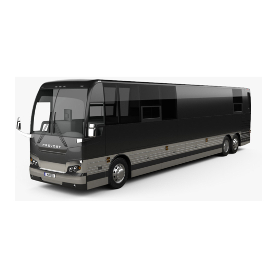
Page 26: Exterior View
2-2 Coach Exterior EXTERIOR VIEW X3-45 VIP MOTORHOME EXTERIOR VIEW (TYPICAL) PA-1638 Owner's Manual X3-45 VIP... - Page 27 Coach Exterior 2-3 1. Engine air filter intake grill 2. Engine compartment curbside door 3. Hinged rear fender 4. Baggage compartment 5. Fuel & DEF filler door 6. Condenser or baggage compartment 7. Entrance door 8. Entrance door power window 9.
- Page 28 2-4 Coach Exterior X3-45 VIP COMERCIAL USE VEHICLE TYPICAL EXTERIOR VIEW (FRONT SLIDE-OUT SHOWN) PA-1638 Owner's Manual X3-45 VIP...
- Page 29 Coach Exterior 2-5 1. Engine air filter intake grill 2. Engine compartment curbside door 3. Hinged rear fender 4. Baggage compartment 5. Fuel & DEF filler door 6. Condenser compartment 7. Entrance door 8. Entrance door power window 9. Engine compartment rear door 10.
-
Page 30: Engine Compartment Components With Driver's A/C
2-6 Coach Exterior ENGINE COMPARTMENT COMPONENTS WITH DRIVER'S A/C ENGINE COMPARTMENT FEATURING VOLVO D13 ENGINE PA-1638 Owner's Manual X3-45 VIP... - Page 31 Coach Exterior 2-7 1. Diesel Oxidation Catalyst (DOC) & Diesel Particulate Filter (DPF) Assembly; 2. Transmission fluid dipstick (if equipped with Allison transmission); 3. Coolant fluid surge tank filler cap; 4. Coolant fluid surge tank sight glass; 5. Power steering fluid reservoir; 6.
-
Page 32: Engine Compartment Curbside Door
2-8 Coach Exterior ENGINE COMPARTMENT CURBSIDE DOOR The engine compartment curbside door provides access to the following (if equipped): Engine compartment rear door release lever; Booster terminals; Rear electrical panel; Rear junction panel; Battery compartment; Fuel filter/water separator; ENGINE COMPARTMENT R.H. SIDE Primary air circuit fill valve and drain cock;... -
Page 33: Exhaust Aftertreatment System Access Door
Coach Exterior 2-9 The door swings out to provide access to the WARNING following: Engine; Unless otherwise specified, do not run the engine when the engine compartment rear door is open. Alternators; Close the engine compartment rear door before starting the engine. Compressor(s);... - Page 34 2-10 Coach Exterior The batteries are housed and secured on the engine R.H. side deck. The battery posts and connections are protected by a watertight cover. The cover is fitted with a built-in vent. The cover can be unlocked and then removed with the use of the same type of hardware that allows opening and closing of the rear fender.
-
Page 35: Engine Radiator Door
Coach Exterior 2-11 ENGINE RADIATOR DOOR The engine radiator door gives access to the radiator electrical fans and power distribution box. RADIATOR DOOR OPENED WARNING WHEN THE ENGINE IS RUNNING… Cooling fans may activate at any moment. RADIATOR DOOR Keep hands away from cooling fans or keep the Open the engine compartment rear door to access radiator door closed the engine radiator door release handle. -
Page 36: Condenser Compartment (A/C)
2-12 Coach Exterior ACCESS TO THE SCR CONDENSER COMPARTMENT (A/C) WARNING After inserting the support rod into the receptacle, make sure the rod supports the door securely from falling down on to your head or body. WARNING External and internal temperatures remain hot long after the engine has been shut down. -
Page 37: Front Electrical And Service Compartment
Coach Exterior 2-13 Temperature sensor is located behind the front FRONT ELECTRICAL AND SERVICE bumper under the driver side head lights. COMPARTMENT To open the front electrical and service compartment door, pull the rod inside the vehicle, next to the driver’s power window or use the key to open from outside the coach. -
Page 38: Baggage Compartments
2-14 Coach Exterior The light in the front electrical and service compartment turns on automatically when the door is opened. BAGGAGE DOOR LOCK AND LEVER To close, pull the door down by the handle rod. Complete the closing of the door by returning the operating handle to its initial position. -
Page 39: Reclining Bumper Compartment
Coach Exterior 2-15 FUEL AND DIESEL EXHAUST FLUID WARNING (DEF) FILLER DOOR To avoid injury, keep hands clear of baggage com- The fuel and Diesel Exhaust Fluid (DEF) filler door is partment door edge and door frame when closing. located on the L.H. side of the coach providing easy filling. -
Page 40: Entrance Door
2-16 Coach Exterior WARNING Do not fill to more than 95% of the fuel tank capa- city. Do not "top off" the tank, doing so may result in fuel spillage when the fuel expands. ENTRANCE DOOR OUTDOOR OPERATION Lock or unlock the entrance door from outside the vehicle by either turning the key in the door lock (counterclockwise to lock, clockwise to unlock), by using the outside key pad, or by using the remote... -
Page 41: Back-Up Camera
Coach Exterior 2-17 mirrors appear smaller and are actually closer than backing-up. The back-up camera is mounted in a they appear. housing with a retractable cover. For additional information, refer to Controls and Instruments and Care and maintenance chapters. NOTE A switch located in the rear electric compartment is used to retract the back-up camera cover for cleaning or maintenance. -
Page 42: Trailer Hitch Load
This hitch must be for recreational use only. The minimum requirement for a trailer weighing up to 20,000 lbs. when coupled to a 20,000 lbs. Prevost Trailer Hitch is as per the following: 1. Trailer must comply with Federal Motor... - Page 43 Coach interior 3-1 SECTION 3 DRIVER’S ''DELIVERY'' SEAT DRIVER AND CO-PILOT SEAT-ISRI PNEUMATIC ISRI SEAT ELECTRICAL ISRI SEAT DRIVER SEAT BELT STEERING WHEEL ADJUSTMENT DRIVER’S WINDOW SHADES INSIDE MIRROR ADJUSTABLE HVAC REGISTERS WINDOWS DRIVER’S POWER WINDOW FIXED WINDOWS AWNING WINDOWS SLIDING WINDOWS PA-1638 Owner's Manual X3-45 VIP...
-
Page 44: Driver's ''Delivery'' Seat
3-2 Coach interior (1) Armrest DRIVER’S ''DELIVERY'' SEAT Rotate control knob to select desired arm- resting The driver's "delivery" seat is standard and legal only angle. When not in use, raise armrest parallel with for driving the vehicle on its initial delivery. It is a backrest. -
Page 45: Driver Seat Belt
If seat belt operation becomes NOTE defective, report to a Prevost Car service center The safety belt must be pulled out slowly and con- immediately. tinuously, otherwise it will lock the reel before the latch plate reaches the buckle. -
Page 46: Steering Wheel Adjustment
3-4 Coach interior STEERING WHEEL ADJUSTMENT Push on the valve button located in the foot-operated control housing to unlock the steering wheel for tilt and telescopic adjustment (refer to "FOOT- OPERATED CONTROLS" on page 6 in Controls and Instruments chapter). TILT AND TELESCOPIC ADJUSTMENT DANGER DRIVER'S WINDOW SUNSHADE Do not adjust the steering wheel while driving. -
Page 47: Windows
Coach interior 3-5 Use the HVAC control panel to set air temperature CAUTION (refer to "HVAC CONTROL UNIT" on page 20 Controls & Instruments chapter). Never try to open or close the awning window by pulling or pushing directly on the window; this could damage the opening mechanism gearbox. - Page 48 3-6 Coach interior NOTE If the sliding window electrical circuit is inop- erative, the power sliding window can be manually closed by removing the lateral plastic trim located on the R. H. side of the window to access the drive belt.
- Page 49 Controls and Instruments 4-1 SECTION 4 DRIVER’S AREA OVERVIEW KEYS REMOTE ENTRY TRANSMITTER ENTRANCE DOOR KEY EXTERIOR COMPARTMENT KEY UTILITY COMPARTMENT KEY FUEL FILLER DOOR KEY (OPTION) IGNITION SWITCH ACCESSORIES START FOOT-OPERATED CONTROLS BRAKE PEDAL ACCELERATOR PEDAL STEERING WHEEL ADJUSTMENT UNLOCK AIR VALVE STEERING COLUMN CONTROLS MULTI-FUNCTION LEVER STEERING WHEEL CONTROLS...
- Page 50 AUTOMATIC FIRE DETECTION AND SUPPRESSION SYSTEM (AFSS) PROTECTION PANEL CRUISE CONTROL TURNING THE SYSTEM ON SETTING A CRUISING SPEED PREVOST AWARE ADAPTIVE CRUISE BRAKING TURNING THE ACB SYSTEM ON TURNING OFF THE ACB SYSTEM MAINTAINING A SET FOLLOWING DISTANCE DRIVER WARNINGS...
-
Page 51: Driver's Area Overview
Controls and Instruments 4-3 DRIVER’S AREA OVERVIEW DRIVER'S AREA 1. Lateral control panel 2. DOT certification plate 3. OBD (On Board Diagnostics) receptacle 4. Foot operated steering wheel adjustment knob 5. Dashboard 6. Rear-view monitor (optional) 7. Front service door unlocking pull rod 8. -
Page 52: Keys
4-4 Controls and Instruments KEYS Press any FOB button again or unlock the entrance door using the keypad. Four different keys and a set of remote entry transmitters are provided with the vehicle. ENTRANCE DOOR KEY Use the entrance door key to lock or unlock the door REMOTE ENTRY TRANSMITTER from the outside. -
Page 53: Fuel Filler Door Key (Option)
Controls and Instruments 4-5 The ignition switch doubles as the battery master FUEL FILLER DOOR KEY (OPTION) switch. Any position other than OFF activates the Use this key to lock or unlock the fuel filler door. electrical circuits. The ignition switch is located on the lower left side of the dashboard. ... -
Page 54: Foot-Operated Controls
Immediately report any brake system problem to severe property damage, serious personal injury or your company or directly to the nearest Prevost or death. Prevost-approved service center. Do not "fan" or "pump" the brake pedal. This... -
Page 55: Steering Column Controls
Controls and Instruments 4-7 (4) Courtesy Blinkers STEERING COLUMN CONTROLS Clearance and parking lights can be flashed by Many of the most frequently used controls are pressing the button located on the lever tip. conveniently placed on the steering column or the (5) Windshield Washer Control steering wheel, just like a passenger car. ... -
Page 56: Steering Wheel Controls
4-8 Controls and Instruments STEERING WHEEL CONTROLS RIGHT STEERING WHEEL CONTROLS LEFT STEERING WHEEL CONTROLS THE STEERING WHEEL CONTROLS INCLUDE THE FOLLOWING FUNCTIONS: 1, 8 Shift Down, Shift Up (I-Shift Transmission Only) Use these buttons to shift down or shift up manually the transmission range as would do the “-” & “+” keys on the I-Shift gear selector keypad. - Page 57 Controls and Instruments 4-9 Retarder / Engine Brake Off Press this button to cancel operation of the transmission retarder. On vehicles equipped with engine brake, this button is a momentary switch that will cancel the Engine Brake LOW or Engine Brake HIGH mode and switch the engine brake to AUTO mode.
-
Page 58: Horns
4-10 Controls and Instruments HORNS The electric horn (city horn) and air horn (highway horn) are operated from the steering wheel center pad. Use the Horn Selector switch located on the lateral control panel to select the appropriate horn type. NOTE When the vehicle is stationary, the electric horn will sound to inform the driver that a fire is detected... -
Page 59: Lateral Control Panel
A led on the switch shows that you can now set the vehicle at a desired cruising speed. For operation of the cruise control, refer "CRUISE CONTROL" on page 44 "PREVOST AWARE ADAPTIVE CRUISE BRAKING " on page 46 in this section. -
Page 60: Mirror Controls
4-12 Controls and Instruments Use this rocker switch to open or close the driver’s power window. CAUTION MIRROR CONTROLS Close power window when parked or leaving the coach unattended. NOTE If the mirror assemblies on your vehicle do not Outside Rear View Mirror Heat (Optional) include convex mirrors, only one mirror control Press this rocker switch to clear fog, knob will be installed for both mirrors. -
Page 61: Parking Brake Control Valve
NOTE DANGER Prevost vehicles are designed to operate within Do not drive the vehicle with the level low selector specific weight load/ranges for each axle (GAW) switch in any position other than OFF, as this may and for total vehicle weight (GVW). -
Page 62: 12-Volt Appliances Socket
4-14 Controls and Instruments WARNING To prevent a fire, never put paper or plastic wrap- pers in the ashtray. Empty ashtray often. CIGAR LIGHTER Push lighter in to activate. When ready to use, it will spring out automatically. Replace lighter in non- activated position. -
Page 63: Dashboard
Controls and Instruments 4-15 DASHBOARD DASHBOARD 1. L.H. dashboard panel 2. Instrument cluster 3. Vehicle clearance information 4. R.H. dashboard panel 5. HVAC control unit 6. Air registers 7. Brightness control 8. Driver information display (DID) 9. Ignition switch 10. On-Screen tire pressure monitoring system display PA-1638 Owner's Manual X3-45 VIP... -
Page 64: Control Switches
4-16 Controls and Instruments CONTROL SWITCHES NOTE Daytime running lights will be automatically High quality laser-engraved switches are used to canceled when the exterior lighting switch is fully control many of the features of the vehicle. Many depressed (second position). switches have an embedded indicator LED to inform the driver at a glance which features are active. - Page 65 Controls and Instruments 4-17 Windshield Upper Section Defrosting (Option) Wheelchair Lift (Option) The coach may be equipped with an Supply electrical power optional defrosting system in the upper wheelchair lift system by pressing down windshield section. Press the rocker on the rocker switch. Refer to Other switch to activate the blower in order to Features for instructions on operating clear fog, frost or thin ice from either...
- Page 66 4-18 Controls and Instruments Fast Idle Engine Brake / Transmission Retarder For extended idling periods, run the Use this switch to select between the engine at fast idle. Press down this transmission retarder or the engine rocker switch to engage fast idle. This brake when using the vehicle speed increases engine...
-
Page 67: R.h. Dashboard Panel
Controls and Instruments 4-19 CAUTION CAUTION Vehicle clearance is higher when the ventilation Engage DCDL only under poor road surface hatch is open (if installed) , hi-buoy is selected or if conditions. additional equipment is installed on the roof. DCDL will not engage and will disengage in speed higher than 5 mph. -
Page 68: Hvac Control Unit
4-20 Controls and Instruments High Fan Speed To prevent battery run-down, the central A/C and heating systems will not operate if the charging Use this rocker switch located on the system is not working properly. dashboard’s R.H. side panel for locking or unlocking the entrance door from the When the A/C system is running, park at least 4 feet driver’s seat. - Page 69 Controls and Instruments 4-21 Heating Mode Indicator Driver's Section Temperature Setting This red LED illuminates when the The temperature displayed on the system is heating. driver's side HVAC control unit is the temperature set point. To increase the temperature set point, press the "+"...
-
Page 70: Air Registers
4-22 Controls and Instruments Adjustable air registers feed air to the driver's area. NOTE Three are located in the dashboard and one near the door . Use the HVAC control panel to set air Upon starting of the vehicle, when the ambient temperature is very cold and so is the inside of the temperature and fan speed. -
Page 71: Instrument Cluster
Controls and Instruments 4-23 INSTRUMENT CLUSTER 1. Tachometer 2. Telltale lights 3. Speedometer 4. Front brake air pressure (secondary) 5. Fuel level 6. Front brake air pressure (primary) 7. Driver Information Display (DID) 8. Oil pressure indicator 9. DEF (Diesel Exhaust Fluid) level indicator 10. -
Page 72: Driver Information Levels
4-24 Controls and Instruments DRIVER INFORMATION LEVELS instrument cluster includes analog instruments. It also presents two devices to communicate information to the driver, the telltale lights and the Driver Information Display (DID). Indications and warnings are presented according to three levels of attention required: FIRST LEVEL - TELLTALE LIGHTS ... -
Page 73: Analog Indicators
Indicates the vehicle speed in miles per hour (mph) and kilometers per hour (km/h). The LEDs above the instrument work in conjunction with AWARE Adaptive Cruise Braking (ACB) system. Refer to “Prevost Aware Adaptive Cruise Braking” paragraph for further details. - Page 74 4-26 Controls and Instruments Engine Coolant Temperature (°F) Indicates the operating temperature of the engine coolant in °F. The normal reading should be between 170°F and 222°F (80°C to 106°C). The temperature limit is dependent on the electronic program for the engine model.
- Page 75 Controls and Instruments 4-27 Front Brake Air Pressure Gage (Secondary System) Indicates the front brake air system pressure in psi. The normal operating pressure is from 122 to 140 psi. The low air pressure indicator LED on the gage and the STOP telltale light illuminate when the front brake air system (secondary) pressure drops below 85 psi.
- Page 76 4-28 Controls and Instruments Rear Brake Air Pressure Gage (Primary System) Indicates the rear brake air system pressure in psi. The normal operating pressure is from 122 to 140 psi. The low air pressure indicator LED on the gage and the STOP telltale light illuminate when the rear brake air system pressure drops below 85 psi.
-
Page 77: Telltale Lights
Controls and Instruments 4-29 Fuel Level Indicates the amount of fuel remaining in the fuel tank. At the beginning of the red area, there is approximately 48 gallons (182 liters) left in the tank. NOTE A pop-up message will appear in the DID informing that there is only 24 gallons (92 liters) left in the fuel tank. - Page 78 4-30 Controls and Instruments Turn Signal Indicators Flashes when the right or left turn signals are activated. Signal right and left turns by operating the multi-function lever. See "MULTI-FUNCTION LEVER" on page 7 in this section. NOTE The turn signals are automatically activated when the vehicle is backing up. Parking Brake Or Emergency Brake Applied Illuminates when the emergency/parking brake is applied. ...
- Page 79 Controls and Instruments 4-31 Charging System Warning Light Indicates a malfunction of the charging system or a low battery voltage condition. NOTE To identify if an alternator is defective (1=lower alternator, 2=upper alternator), perform a system diagnostic using the Driver Information Display DIAGNOSTICS menu. Select VIEW ACTIVE FAULTS and then ELECTRICAL SYSTEM.
-
Page 80: Stop, Check And Information Telltale Lights
4-32 Controls and Instruments Information Telltale Light STOP, CHECK AND INFORMATION TELLTALE LIGHTS The INFO indicator light comes on when there is a new information message or an abnormal status is STOP, CHECK and INFORMATION telltale lights detected by the electronic control unit. A pictogram illuminate automatically to draw the attention of the or text or both are shown in the DID in addition to the driver and their associated messages are displayed... - Page 81 Controls and Instruments 4-33 Selecting A Menu The outside air temperature, fuel flow and the odometer (Allison transmission) or the current gear Menus are placed in a cascade arrangement. Use position (transmission I-Shift) are part of the default the steering wheel controls buttons to scroll through display.
- Page 82 4-34 Controls and Instruments Scrolling Through The Menus Without Using The Steering Wheel Buttons In case of failure of the steering wheel buttons, it is still possible to gain access to the menus or acknowledge the pop-up messages to return to the default display.
-
Page 83: Pictograms Displayed On The Driver Information Display (Did)
Controls and Instruments 4-35 PICTOGRAMS DISPLAYED ON THE DRIVER INFORMATION DISPLAY (DID) NOTE In certain situations, the pictogram displayed represents a system or a function of the vehicle. A particular pictogram may be displayed with different messages. In that situation, it is very important to pay attention to the message displayed with the pictogram. - Page 84 4-36 Controls and Instruments POP-UP MESSAGES Acknowledge messages by pressing the escape (ESC) button on the steering wheel. Acknowledgement of pop-up messages and warnings stops the audible warning. Pop-up Pictograms PICTOGRAM DESCRIPTION High Engine Oil Temperature Engine Coolant Temperature Low engine coolant level CHECK ENGINE COOLANT LEVEL AT Warns the driver that the engine coolant level has reached the recovery tank low level...
- Page 85 Controls and Instruments 4-37 Pop-up Pictograms TCS traction control system and electronic stability control At vehicle ignition, the TCS icon appears for approximately 2 seconds and then disappears. If it remains on steadily (not flashing) after ignition, or if it is on steadily while you are driving, the TCS system may not be fully functional or the operation may be completely disabled.
- Page 86 4-38 Controls and Instruments Pop-up Pictograms Battery Voltage Warning This pictogram indicates that the battery voltage is too high, too low or the 12 volt / 24-volt battery arrangement is not equalized. The value LOW or HIGH is displayed at the right of the pictogram to indicate if the voltage is too low or too high.
- Page 87 Controls and Instruments 4-39 Pop-up Pictograms Low Windshield Washer or Headlights Washer Fluid Level Illuminates when the windshield washer or the headlight washer fluid level is low. The washer fluid containers are located inside the front service compartment. WARNING Do not drive without sufficient washer fluid. Differential lock (option) This pictogram indicates that the differential action is locked.
- Page 88 4-40 Controls and Instruments Pop-up Pictograms Leg Fuel Consumption This pictogram is displayed with the value for the fuel consumption for the current leg. Trip Data Function of the DID’s “Time/Distance” menu. Refer to "DRIVER INFORMATION DISPLAY (DID) MENUS " on page 11 in Section 5 Other Features.
- Page 89 Controls and Instruments 4-41 Pop-up Pictograms Fire in engine compartment This pictogram appears if a fire is detected in the engine compartment while the vehicle is on the road. An audible alarm informs the driver when a fire is detected. In case of fire detection when parked (parking brake applied, engine running or not), the electric horn is activated to alert the driver.
- Page 90 4-42 Controls and Instruments STATUS LINE PICTOGRAMS These pictograms will appear in the status line of the DID. Status Line Pictograms PICTOGRAM DESCRIPTION Message Active Alarm Clock Activated Raised Tag Axle Kneeling/Front Suspension Hi-Buoy Active This pictogram appears if the vehicle speed exceeds 12 mph (20 km/h) while the front suspension of the vehicle (kneeling –...
- Page 91 Controls and Instruments 4-43 Status Line Pictograms Allison Transmission Retarder – Braking Level 0, 1, 2, 3, 4, 5, 6 Confirms the retarder hand lever position. Each position corresponds to a given braking level. Refer to "TRANSMISSION RETARDER" on page 10“ in this section. TEST Vehicle Test Confirms that one of the vehicle test modes is active.
-
Page 92: On Board Diagnostic Tool Receptacle
4-44 Controls and Instruments ON BOARD DIAGNOSTIC TOOL RECEPTACLE To ease troubleshooting, you can connect a diagnostic tool through the OBD receptacle to access recorded data. The OBD receptacle is located under the dashboard, on the left side. AUTOMATIC FIRE DETECTION AND SUPPRESSION SYSTEM (AFSS) PROTECTION PANEL The protection panel displays the current system... -
Page 93: Setting A Cruising Speed
Controls and Instruments 4-45 NOTE NOTE The cruise switch and RESUME button do not When driving with cruise control, the vehicle can operate at speeds below 30 mph (50 km/h). still be accelerated by depressing the accelerator pedal in the usual manner. Once the accelerator pedal is released, the vehicle will return to the previously set cruising speed. -
Page 94: Prevost Aware Adaptive Cruise Braking
CRUISE BRAKING steering wheel engine brake control buttons is activated; Prevost AWARE Adaptive Cruise Braking (ACB) is an optional cruise control that not only maintains the set speed, but will also intervene, as needed, to help = Engine Brake Low... -
Page 95: Turning The Acb System On
Prevost’s default ACB is turned on. In addition to the audible and set time gap is 1.7 seconds. -
Page 96: Driver Warnings
4-48 Controls and Instruments intervention, the coach will automatically detected. The driver must intervene to avoid a accelerate back to the original cruise control collision. set speed, and again maintain a set following Solid red: ACB system malfunction. The ACB distance behind the forward vehicle. -
Page 97: Impact Alert
Controls and Instruments 4-49 coach and the forward vehicle is less than the set the use of ACB on downhill runs may cause this alert distance and getting closer. Once the audible to be activated. It is recommended that ACB be warning is given, the driver must increase the disengaged on downhill grades. -
Page 98: Following Distance Alert
4-50 Controls and Instruments FOLLOWING DISTANCE ALERT CONDITION The Following Distance Alert feature is only available when the coach speed is greater than 37 mph (60 km/h), whether or not ACB is engaged. The forward vehicle is slowing down and the distance between your vehicle the coach and the forward vehicle is less than the set distance. -
Page 99: Self-Diagnostic At Start-Up
Controls and Instruments 4-51 condition is detected, one of the following pop-up SELF-DIAGNOSTIC AT START-UP messages will show in the DID. Initiate the self-diagnostic as follows: The engine must be running since at least 15 ACB RADAR MISALIGNMENT seconds with the parking brake applied. ACB RADAR FAULT Trip the CRUISE rocker switch located on the lateral control panel from OFF to ON position. - Page 100 “_ _“. The TPMS display is initially configured to define how many axles and running tires are present on the vehicle. For current Prevost vehicle models, there axles tire configurations.
- Page 101 Controls and Instruments 4-53 Temperature”, “Not all tires monitored” and “Tire pressure not Optimal”. To get the driver’s attention to the alarms, the bottom section of the screen where the alarm message appears will blink to reverse contrast. Pressing any key will acknowledge the alarms that are considered as non-critical and stop the blinking of these alarms message for the remaining of the trip.
-
Page 102: System Malfunction
4-54 Controls and Instruments On the occurrence of an alarm, a beep will sound. The alarm beep could be turned OFF in the alarm settings menu. Spare Tire The spare tire is monitored but it is not taken into account when setting the bottom alarm messages. This is to prevent unnecessary alarms that would otherwise occur, if for example, the spare tire is removed from a vehicle. -
Page 103: Allison Transmission
If the button is held down, the 5th Generation Bus Series Operator’s Manual selection will scroll up or down until the button is available on the Prevost Technical Publication web released or until the highest or lowest possible range site. -
Page 104: Transmission Service Indicator
4-56 Controls and Instruments NOTE WARNING When the diagnostic display mode has been The vehicle service brakes or park brake must be entered, the MODE button is used to view and applied whenever NEUTRAL is selected to toggle through diagnostic code information. Refer prevent unexpected vehicle movement. -
Page 105: Towing Recommendations
Controls and Instruments 4-57 1 (First Range) TOWING RECOMMENDATIONS Select this range when pulling through mud and snow, when speed control is needed for driving up or CAUTION down steep grades or when maneuvering in tight spaces. This range also provides maximum driving When towing the vehicle, the transmission output torque and engine braking power or retarder braking shaft must not be allowed to spin or turn. - Page 107 DISPLAY SETTINGS DIAGNOSTICS MENU PRE-TRIP ASSISTANCE (OPTION) DATA LOG AFTERTREATMENT PASSWORD PREVOST LIAISON (OPTION) INTELLIGENT SLEEP MODE (ISM) TRANSMISSION RETARDER ENGINE BRAKE VOLVO ENGINE BRAKE (VEB) CRUISE CONTROL AND ENGINE BRAKE ABS, TRACTION CONTROL SYSTEM (TCS) & ELECTRONIC STABILITY CONTROL (ESC)
- Page 108 5-2 Other Features REMOTE ENTRY TRANSMITTER PROGRAMMING TRANSMITTERS SLIDE-OUT OPERATION SAFETY PRECAUTIONS FRONT AND REAR SLIDE-OUT OPERATION SLIDE-OUT MANUAL OVERRIDE PROCEDURE SLIDE-OUT TROUBLESHOOTING SLIDE-OUT TROUBLESHOOTING TABLE PA-1638 Owner's Manual X3-45 VIP...
-
Page 109: Exhaust Aftertreatment System
Other Features 5-3 STATIONARY (PARKED) REGENERATION EXHAUST AFTERTREATMENT SYSTEM In a small number of specific engine duty cycles, engine control module may not be capable of The exhaust aftertreatment system consists of two completing an active regeneration. In these units, the filtration and regeneration unit and the situations, the operator will be notified that a selective catalytic reduction SCR unit. -
Page 110: Def Clogging Sequence - Instrument Cluster Telltale Light
5-4 Other Features DEF CLOGGING SEQUENCE – INSTRUMENT CLUSTER TELLTALE LIGHT REGENERATION NEEDED LEVEL 1 solid Diesel particulate filter is becoming full The DPF Regeneration telltale light illuminates to notify the driver that a stationary regeneration (parked) will be required soon. When this lamp is lit, initiate stationary regeneration process at an appropriate time of day. -
Page 111: Selective Catalytic Reduction Unit
Other Features 5-5 Initiating A Stationary (Parked) Regeneration To initiate a stationary regeneration: Park the vehicle in a clear area, vehicle speed NOTE must be 0 mph (0 km/h); At starting of the engine, if a stationary Engine must be on normal idle and fully regeneration is required, the engine coolant warmed up (coolant temperature above temperature must reach 140°F (60°C) before any... - Page 112 5-6 Other Features then passes over a catalyst, the ammonia reacts Things to know about spilt diesel exhaust fluid with the NOx to form nitrogen and water vapor. (DEF): The basic elements of the SCR system consist of a If urea solution comes into contact with the 15.9 gallons (60 liters) DEF tank complete with skin, rinse with plenty of water and remove contaminated clothing.
-
Page 113: Driver Warning And Inducement Measures
Other Features 5-7 DRIVER WARNING AND INDUCEMENT MEASURES Auxiliary Emission Control Device (EACD) defines as any element of design which senses temperature, vehicle speed, engine RPM, transmission gear, manifold vacuum, or any other parameter for the purpose of activating, modulating, delaying, or deactivating the operation of any part of the emission control system. - Page 114 5-8 Other Features DEF TANK LEVEL - DRIVER WARNING AND INDUCEMENT DEF Tank LOW LEVEL Indicator, DID Inducement Conditions / Triggers Message and audible warning Normal DEF tank level sensor reads None None between 100% and 12% 2 Low DEF tank warning DEF TANK LEVEL LOW DEF tank level sensor reads REFILL DEF SOON TO...
- Page 115 Other Features 5-9 DEF QUALITY - DRIVER WARNING AND INDUCEMENT Amber Warning Light & DID Inducement Conditions / Triggers Message And Audible Warning Good DEF quality None None Poor DEF quality detected POOR DEF QUALITY DETECTED Warning message solid SERVICE DEF Engine will derate SYSTEM AT NEXT 25% in <...
- Page 116 5-10 Other Features SCR SYSTEM TAMPERING - DRIVER WARNING AND INDUCEMENT Amber Warning Light, Did Message Inducement Conditions / Triggers And Audible Warning Normal None None No diagnostic troubleshooting code active SCR system tampering SCR SYSTEM FAULT Warning message diagnostic troubleshooting code ENGINE WILL DERATE IN confirmed solid...
-
Page 117: Driver Information Display (Did) Menus
2. Outside Temperature 2. Units 3. Engine Oil Temperature 3. Time/Date 4. Transmission Fluid Temperature 4. Favorite Display Setting 5. Prevost Liaison Compass 5. Display Light 6. Accessories Air Pressure 6. Change Password 7. Battery Voltage 8. A/C Compressor Pressure 9. -
Page 118: Gauges
2. Outside Temperature Selecting this gauge will display the engine oil temperature. 3. Engine Oil Temperature Selecting this gauge will display the engine oil temperature. 4. Transmission Fluid Temperature 5. Prevost Liaison Compass 6. Accessories Air Pressure PA-1638 Owner's Manual X3-45 VIP... -
Page 119: Fuel Data
Other Features 5-13 7. A/C Compressor Pressure Displays the A/C compressor suction pressure value (LoS=low side) and discharge pressure value (HiS=high side). 8. Battery Voltage Displays current 12-volts and 24-volts systems voltage. 9. Allison Transmission Oil Life Displays the percentage of the calculated remaining life of the transmission oil. New oil is displayed as 99%. -
Page 120: Time/Distance
5-14 Other Features 2. Fuel Flow/ ECO% The lower numerical value (0.0) indicates the instantaneous fuel consumption. In this menu, you can reset the upper numerical value which is the average fuel consumption (0.7). To reset, hold ENTER button for 1 second. This menu also displays the percentage of trip made on regenerated electricity (10%). -
Page 121: Vehicle Messages
Other Features 5-15 4. Average Trip Speed This function displays the average speed for the current travel. The average trip speed is calculated as the distance traveled divided by the time the engine has been running (since the last reset). Two average trip speeds can be measured, corresponding to leg 1 and leg 2. - Page 122 5-16 Other Features 2. Units Use this function to select desired unit formats for: Distance (miles or km); Fuel consumption (km/l, l/100km, mpg US or IMP); Temperature (°C or °F). Brake lining: 1/32 inch, mm, %. Available on vehicles equipped with a pad wear indicator.
- Page 123 Other Features 5-17 4. Favorite Display Setting Use this menu to select your favorite display gauges 1, 2 and 3 and replace the default gauges. On vehicles provided with the I- Shift transmission, Favorite Display Gauge 3 cannot be edited as it is kept for display of the transmission status.
-
Page 124: Diagnostics Menu
5-18 Other Features DIAGNOSTICS MENU The Diagnostics menu enables fault tracing on the control units in the vehicle to check for faults. Instrument tests are available to check the telltales, gauges, display and speaker. The part number of a control unit can be identified in the part number menu. -
Page 125: Pre-Trip Assistance (Option)
Other Features 5-19 5. Reset Inactive Faults Use this menu to delete an inactive fault for a particular control unit. Note: it is not possible to delete inactive faults of the Engine ECU. 6. Vehicle Tests Use this menu to perform tests on several components and systems: Dashboard switches (Mux Input Test) Electric motors, valve and pump contactors (Electric Motors Test) In case of overheating of the engine due to a malfunction of the radiator fan you... - Page 126 5-20 Other Features 2. Air leakage Monitor The Air Leakage check allows the driver to accurately measure the amount of air pressure drop in the front and rear brake air systems. After selecting this test from the DID, you are prompted to apply the service brake for 60 seconds. After applying and holding the service brake for 60 seconds, the DID will display the amount of pressure drop in the brake system.
-
Page 127: Data Log
Other Features 5-21 DATA LOG 1. Vehicle ID 2. Total Data Total Data menu indicates the accumulated engine values that have been logged during the lifetime of the engine ECU. Available information: Total distance traveled Total fuel used Total engine hours Total idle time Total PTO hours Total engine revolutions... -
Page 128: Aftertreatment
5-22 Other Features 4. Reset Trip Data This menu can only be accessed if the correct password has been entered. Use this function to reset measurements of the Trip Data menu before each new trip or leg. AFTERTREATMENT This menu permits to the driver to initiate a stationary regeneration, to check the status of the aftertreatment system and to interrupt regeneration. -
Page 129: Password
Inactive Faults PREVOST LIAISON (OPTION) The Prevost Liaison system provides cellular communication between the driver and the fleet operator. The driver can send and receive short text messages, which are visible through the Driver Information Display. PA-1638 Owner's Manual X3-45 VIP... - Page 130 5-24 Other Features The following menus are available: 1. Read Message Quick Response (only available if there is a message available) 2. Send Message Driver & Equipment Dispatch Messages Free Text 3. Other Info Comm Liaison Info Mailbox Info GPS Info INI Info Configuration Info PA-1638 Owner's Manual X3-45 VIP...
-
Page 131: Intelligent Sleep Mode (Ism)
Other Features 5-25 The retarder is provided with control buttons on the INTELLIGENT SLEEP MODE (ISM) steering wheel and a lever on the steering column (refer "TRANSMISSION RETARDER" The ISM is a battery- saving mode designed to page 10 in Section 4 Controls and instruments). protect the battery State Of Charge (SOC). -
Page 132: Volvo Engine Brake (Veb)
5-26 Other Features NOTE WARNING When using engine brake LOW or HIGH When descending significant grades, use the ser- mode, pressing the steering switch OFF button will vice brake as little as possible. If the engine does switch back to the default AUTO mode. -
Page 133: Abs, Traction Control System (Tcs) & Electronic Stability Control (Esc)
Other Features 5-27 100% if the selected cruise speed is exceeded by maximum braking performance while maintaining approximately 2 km/h (1.25 mph). Manually adequate control on slippery roads. switching to engine brake LOW or HIGH using The basis of ABS is constant monitoring of wheel the steering wheel switches will deactivate the parameters during braking. -
Page 134: Driver Controlled Differential Lock (Dcdl)
5-28 Other Features To reduce the risk of rollover, the RSP system The purpose of the DCDL is to provide maximum detects potential rollover conditions and slows the vehicle traction and control on unfavorable road vehicle both by reducing engine throttle (and hence, surface conditions. -
Page 135: Locking The Dcdl
Other Features 5-29 easier to turn a short corner. The tag axle shortens LOCKING THE DCDL the wheelbase and allows tighter turning. Raising When encountering poor road conditions where the tag axle transfers extra weight and additional maximum traction needed, follow traction to the drive wheels providing improved recommended procedures:... -
Page 136: Keyless Operating Instructions
5-30 Other Features KEYLESS OPERATING INSTRUCTIONS Press the 9/0 key for 2 seconds (no access code required). Entering a valid access code enables secure NOTE operation. After entering the access code, the keypad is enabled for 5 seconds and a fifth button The lock function will not function when the ignition press initiate an action. -
Page 137: Remote Entry Transmitter
Other Features 5-31 REMOTE ENTRY TRANSMITTER Enter the chosen personal code (three confirmation beeps will be heard). Hand held transmitters (key FOB) can be used to Re-enter the code to confirm the entry (four control the keyless door lock system. confirmation beeps will be heard). -
Page 138: Programming Transmitters
5-32 Other Features PROGRAMMING TRANSMITTERS to clear all ice or snow may seriously damage the inflatable seal. Up to 20 transmitters can be used with the keyless The parking brake must be applied. entry system. To add or replace transmitters, the system must be first put into learn mode using the The transmission must be in the "NEUTRAL"... -
Page 139: Slide-Out Manual Override Procedure
Other Features 5-33 is activated. The following actions will be done in sequence: Deflation of the inflatable seal Movement of the slide-out to its full "OUT" position Then releasing the rocker switch will permit the following actions: Re-inflation of the seal When the rocker switch is released, the green SLIDE-OUT CONTROL PAD indicator light goes out. - Page 140 5-34 Other Features However, it is very important to follow all the instructions very carefully to assure that the inflatable seal or the retraction mechanisms are not damaged. Preliminary Conditions For Manual Override Procedure Before using the slide- out manual override procedure, make sure that the problem cannot be solved by one of the following simple checks:...
- Page 141 Other Features 5-35 CAUTION Slow down on the closing speed as the slide-out approaches its closed position. As soon as the “in limit” stoppers come in contact with their bearing surface, stop immediately the power drill rotating movement. Not doing so could overload the drive mechanism and cause damage to the reduction gearbox.
-
Page 142: Slide-Out Troubleshooting
5-36 Other Features NOTE NOTE When air pressure is relieved using the shut-off The front slide-out motor is located inside the 2nd valve, the normal extending and retracting oper- baggage compartment while the rear slide- out ation cycle is disabled, for that reason the slide-out motor is accessible from inside the vehicle, under cannot be moved with the control pad. - Page 143 Other Features 5-37 To initiate fault diagnostic, use the DID right after operating the slide-out without cycling the ignition switch. NOTE The DID is the main tool for troubleshooting a mul- tiplex vehicle. It is essential to have it in working condition.
-
Page 144: Slide-Out Troubleshooting Table
5-38 Other Features SLIDE-OUT TROUBLESHOOTING TABLE PROBLEM CAUSE CORRECTIVE ACTION Something is defective and may eventually create an issue if not repaired. The problem may be: A. Faulty limit sensor causing slide- out stop overcurrent; network problem causing the transmission inhibit slide- safety to be non-operational;... - Page 145 Other Features 5-39 PROBLEM CAUSE CORRECTIVE ACTION Not enough air pressure in the accessory air tank to permit Run the engine at fast idle a few minutes to increase proper operation of the vacuum air pressure in the accessory air tank and try again. generator;...
- Page 146 5-40 Other Features PROBLEM CAUSE CORRECTIVE ACTION Slide- out moves Adjust the sensor position in order to have contact of when vehicle is mov- Inflatable seal not inflated the stoppers against the structure at the time when the ing. system stops the slide-out retraction. Slide- out moves when vehicle is mov-...
- Page 147 Other Features 5-41 PROBLEM CAUSE CORRECTIVE ACTION Inflatable seal and/or wiper seal Check both seals condition. damaged or unstuck; Insufficient air pressure in the Check the pressure regulator, the relieving shut-off seal; valve and the seal valve condition. No air pressure in the slide-out Check the slide-out air pressure inlet valve condition pneumatic system;...
- Page 149 Starting and Stopping Procedures 6-1 SECTION 6 STARTING THE ENGINE STARTING FROM THE DRIVER’S SEAT STARTING FROM THE ENGINE COMPARTMENT COLD WEATHER STARTING JUMP STARTING ENGINE PROTECTION SYSTEM AUTOMATIC ENGINE SHUTDOWN IDLE SHUTDOWN TIMER ENGINE BLOCK HEATER ENGINE WARM-UP ALLISON TRANSMISSION WARM-UP STARTING THE VEHICLE AFTER A FIRE ALARM PA-1638 Owner's Manual X3-45 VIP...
-
Page 150: Starting The Engine
6-2 Starting and Stopping Procedures STARTING THE ENGINE Apply the spring- loaded parking brake by pulling the parking brake control button all the way up; In normal circumstances, the engine should be started from the driver’s seat. However, a rear-start Place transmission in neutral;... -
Page 151: Starting From The Engine Compartment
Starting and Stopping Procedures 6-3 NOTE 1. Set the main electrical shut-off switch and ignition to the ON position. If the accelerator pedal is depressed before starting, release and wait 30 seconds before 2. Press the rear start button to start engine from attempting to restart. -
Page 152: Cold Weather Starting
6-4 Starting and Stopping Procedures cables are used correctly and only in emergencies. COLD WEATHER STARTING To jump start, use another 24 volt DC, negative When starting a cold engine, the intake air will be grounded, power source. Use only jumper cables warmed up with the intake air preheater. -
Page 153: Engine Protection System
Starting and Stopping Procedures 6-5 4. Connect the other end of the red jumper cable WARNING to the positive (+) terminal on the booster block; Before attempting to jump start, make sure the parking brake is applied and the transmission is in 5. -
Page 154: Automatic Engine Shutdown
6-6 Starting and Stopping Procedures The engine will shut down at the set time under the AUTOMATIC ENGINE SHUTDOWN following conditions: Prior to an actual automatic shutdown, the engine Vehicle speed is 0; will automatically derate, go to idle, and then stop as the vehicle speed gets below 2 mph (3 km/h). -
Page 155: Engine Warm-Up
Starting and Stopping Procedures 6-7 ALLISON TRANSMISSION WARM-UP With automatic transmission, when temperature falls below -20°F (-29°C), the CHECK telltale light illuminates after the engine is started, and a reminder tone will sound. In this case, the transmission will be locked in neutral (N) until the transmission temperature rises above -20°F (-29°C) and the CHECK telltale light goes out. ... - Page 157 Safety Features and Equipment 7-1 SECTION 7 EMERGENCY EXITS ELECTRIC AWNING WINDOW ELECTRIC SLIDING WINDOW FIXED WINDOW EMERGENCY EQUIPMENT FIRE EXTINGUISHERS FIRST-AID KIT WARNING REFLECTORS JACK AND TOOLS SPARE PARTS KIT AUTOMATIC FIRE SUPPRESSION SYSTEM (AFSS) TIRE PRESSURE MONITORING SYSTEM CHANGING WHEEL EMERGENCY AIR-FILL VALVES EMERGENCY AND PARKING BRAKES...
-
Page 158: Emergency Exits
7-2 Safety Features and Equipment EMERGENCY EXITS Locate and learn how to use all possible emergency exits. It is good practice to inform all guests or passengers of the location of exits and how to use them in case of an emergency. ELECTRIC AWNING WINDOW ELECTRIC SLIDING WINDOW FIXED WINDOW... -
Page 159: Jack And Tools
Safety Features and Equipment 7-3 NOTE The Manual Activation Switch is used when immediate discharge of the fire extinguisher and engine shutdown is desired. Operational Sequence (Fire) 1. A fire detector or linear thermal detector WARNING REFLECTORS LOCATION (X3 SERIES) detects a fire in the engine compartment and sends a signal to the Protection Panel in the JACK AND TOOLS... -
Page 160: Tire Pressure Monitoring System
7-4 Safety Features and Equipment Description 6. The system must be reset and the fire System includes the following elements: extinguisher removed replaced accordance with the System Reset portion of Special tire valves; the Kidde Dual Spectrum Operation & Maintenance Manual. RF sensor inside each tire, fixed to the valve. - Page 161 Safety Features and Equipment 7-5 right, and then moves to the next axle, counting axles from front to rear. Learn Wheel ID This menu allows learning new wheel sensors ID. The user can learn only one wheel, several wheels or wheels vehicle.
- Page 162 7-6 Safety Features and Equipment Set Target Pressures This menu allows the end user to fine-tune the target pressure setting, taking account for the specific operating conditions (cold weather operation or unloaded operation). The end user can readjust the target pressure within +30% and -20% of the factory set target pressure but not outside this range.
-
Page 163: Changing Wheel
Safety Features and Equipment 7-7 Both air system emergency fill valves are fitted with standard tire valve stems. The air systems can be filled using any standard external air supply line. The fill valve located in the engine compartment supplies air for all systems (brakes, suspension and accessories). -
Page 164: Emergency And Parking Brakes
7-8 Safety Features and Equipment NOTE The telltale panel audible alarm will sound if the ignition switch has been turned to OFF without applying the parking brake. The same beep will sound if pressure is still applied to the service brake pedal. -
Page 165: Daytime Running Lights
Safety Features and Equipment 7-9 publications USB key and website. COMPARTMENT LIGHTING Baggage compartments service DAYTIME RUNNING LIGHTS compartments lights are automatically turned on when the corresponding compartment door is The daytime running lights system provides added opened. A pictogram will appear on the status bar of safety by making the front of the vehicle more visible the Driver Information Display (DID) when the to other drivers during the day. -
Page 166: Essential Functions To Operate The Vehicle (Basic Limp-Home Functions)
7-10 Safety Features and Equipment ESSENTIAL FUNCTIONS TO OPERATE THE VEHICLE (BASIC LIMP-HOME FUNCTIONS) Even with a defective CECM (Chassis Electronic Control Module) or a CAN network problem, essential base functions are maintained to rear start the vehicle from the engine compartment and drive in a secure manner. - Page 167 Care and Maintenance 8-1 SECTION 8 CLEANING SEAT UPHOLSTERY PLASTIC AND VINYL WINDOWS STAINLESS STEEL HIGH PRESSURE LAMINATE RUBBER COMPONENTS FLOOR CLEANING EXTERIOR SURFACES WINDSHIELD FLUID LEVEL VERIFICATION ENGINE OIL LEVEL TRANSMISSION FLUID LEVEL POWER STEERING FLUID LEVEL DRIVE AXLE WHEEL BEARING OIL LEVEL FRONT AND TAG AXLE WHEEL HUBS COOLANT FLUID LEVEL WINDSHIELD WASHER &...
- Page 168 8-2 Care and Maintenance PREPARATION STEP 1: RIGHT SIDE STEP 2: ENGINE COMPARTMENT RIGHT SIDE AREA STEP 3: ENGINE COMPARTMENT STEP 4: REAR LEFT SIDE STEP 5: FRONT LEFT SIDE STEP 6: FRONT STEP 7: FRONT RIGHT SIDE STEP 8: INSIDE THE VEHICLE WITH ENGINE RUNNING PA-1638 Owner's Manual X3-45 VIP...
-
Page 169: Cleaning
Do not soak the stain; Rub the stain with a damp cloth; Use only approved cleaning products such as Prevost A.P.C., all- purpose cleaner (Prevost # Rinse cloth after each application. 683664). Never use stain protection products on new fabrics. ... -
Page 170: Plastic And Vinyl
The paint finish manufacturer's instructions. Stainless steel cleaning is attacked by the abrasive effects of airborne solution may be ordered from Prevost quoting part particles and corrosive pollutants. number 680356. Before washing the exterior of the vehicle, close the fresh air dampers using the “REC”... -
Page 171: Windshield
Care and Maintenance 8-5 manufacturer's recommendations cleaning. WINDSHIELD Rinse well with water. To prevent windshield wiper streaking, keep silicone The vehicle exterior should be cleaned, waxed and sprays away from windshield. Remove road film and buffed when water droplets no longer form on the wax build-up from windows with lukewarm soap and painted surfaces. -
Page 172: Transmission Fluid Level
8-6 Care and Maintenance The transmission fluid level dipstick is accessible through the engine compartment rear door and is located on the left side of the engine. To check the transmission fluid level, a "cold check" and a "hot check" must be performed. A cold check must be made when the transmission fluid is between 60 F and 120... -
Page 173: Power Steering Fluid Level
Care and Maintenance 8-7 TRANSMISSION FLUID LEVEL DIPSTICK (TYPICAL) CAUTION The fluid level rises as fluid temperature rises. Do not add fluid above the "cold run" band before the transmission reaches 180 F to 220 F (82 C to Hot Check Make sure the transmission fluid temperature is between 160ºF and 200ºF (71ºC and 93ºC) before performing the hot check. -
Page 174: Coolant Fluid Level
8-8 Care and Maintenance Level Switches COOLANT FLUID LEVEL Both tanks are equipped with a level switch. A The coolant system has two tanks; the surge tank message will appear on the cluster according to (A) and the recovery tank (B). which switch is activated. -
Page 175: Windshield Washer & Headlights Washer Reservoirs
Care and Maintenance 8-9 Check for cracks and signs of abrasion on the blades WINDSHIELD WASHER & HEADLIGHTS that could indicate contact with debris or obstruction WASHER RESERVOIRS during operation; The windshield washer reservoir and headlights Check the bottom of the shroud cover and remove washer reservoir are located in the front service debris that could have accumulated. -
Page 176: Fire Extinguishers
8-10 Care and Maintenance accessory air tank drain cock is accessible from the FRONT SERVICE COMPARTMENT front service compartment. The wet, primary, secondary and optional air tanks FIRE EXTINGUISHERS must be purged at every oil change or at least every 12,500 miles (20 000 km). -
Page 177: Driver's A/C Compressor Belt
Care and Maintenance 8-11 DRIVER'S A/C COMPRESSOR BELT For vehicles equipped with driver’s A/C, the air conditioning compressor is driven by a multi-V-belt. Belt tension is achieved by an automatic belt tensioner. No adjustment is required. FUEL FILTERS WITH VOLVO D13 ENGINE The optional Fuel Pro 382 diesel fuel filter system BELT TENSIONER consists of a permanently mounted fuel processor, a... -
Page 178: Alternator Drive Belts
8-12 Care and Maintenance Belt tension should be within the following values: New belts: 90-100 lbs. Used belts: 75-85 lbs. Check belt tension using a belt strand tension gauge. Once adjustment completed, allow the engine to run for about ten minutes. Check belt tension and adjust if needed. -
Page 179: Hose Inspection
Care and Maintenance 8-13 Hose Service Life Hoses have a limited service life. Thoroughly inspect hoses annually. Look for surface damage or indications of twisted, worn, crimped, cracked or leaking lines. Replace damaged hoses immediately. Hoses should be replaced during major overhaul or after a maximum of seven service years. ... -
Page 180: Wheel Bearings
8-14 Care and Maintenance The TPMS presents pressure readings of each tire EXTERIOR LIGHTING VERIFICATION WITH as a +/- deviation from the wanted target. TEST MODE If a tire reads within +/- 3 PSI no adjustment is This useful function allows quick verification of the needed. - Page 181 Care and Maintenance 8-15 Using The Test Mode: First, test the functionality of the commands related to the exterior lighting: Activate the right directional signal and check that the corresponding cluster telltale light illuminates. Activate the left directional signal and check that the corresponding cluster telltale light illuminates.
- Page 182 8-16 Care and Maintenance EXTERIOR LIGHTING (X3-VIP) PA-1638 Owner's Manual X3-45 VIP...
-
Page 183: General Recommendations
WARNING Understand the basic principles of vehicle Report all problems affecting passenger or driver operation; safety to a Prevost service center. Have problems corrected immediately. Always maintain the vehicle in good running condition; Do not drive with low fuel. If the fuel tank runs dry, the engine will not start until the air is bled from the fuel system. ... - Page 184 8-18 Care and Maintenance X3 SERIES COMPONENT IDENTIFICATION (MAY DIFFER SLIGHTLY FROM ACTUAL VEHICLE) PA-1638 Owner's Manual X3-45 VIP...
- Page 185 Care and Maintenance 8-19 1 Accessories air tank drain cock 21 Primary fuel filter 2 Accessories air filter 22 Secondary fuel filter 3 Steering drag link 23 Power steering fluid tank 4 Height control valve (front) 24 Engine oil filter 5 Steering tie rod 25 Road Side Alternator 6 Accessories air tank...
-
Page 186: Walk-Around Inspection (Before Every Trip)
8-20 Care and Maintenance WALK-AROUND INSPECTION (BEFORE EVERY TRIP) It is good practice to make a visual inspection of key areas on the vehicle every day (or before every trip for private coaches) and to correct any problem found. X3 SERIES WALK-AROUND INSPECTION NOTE Inspect the coach in a circular manner as shown in the illustration. -
Page 187: Step 2: Engine Compartment Right Side Area
Care and Maintenance 8-21 Check condition of tires: properly inflated, no serious cuts, bulges, tread wear or any signs of misalignment; valve stems not touching wheels or rims; valve caps in place and no objects stuck between the wheels. STEP 2: ENGINE COMPARTMENT RIGHT SIDE AREA Drain wet air tank by opening drain cock. -
Page 188: Step 6: Front
8-22 Care and Maintenance STEP 6: FRONT Check for damage and clean if dirty. Check windshield wiper arms for proper spring tension. Check wiper blades for any damage, “dead” rubber and attachment to arm. Check clearance and identification lights, they should be clean. Check high and low beams, they should be clean. - Page 189 Technical Information 9-1 SECTION 9 DIMENSIONS AND WEIGHTS CAPACITIES TURNING RADIUS FUEL TYPE BIODIESEL FUEL WHEELS AND TIRES RECOMMENDED TIRE INFLATION PRESSURE AT MAXIMUM COLD LOAD BELTS VOLVO D13 ENGINE ALLISON TRANSMISSION X3-45 VIP MOTORHOMES X3-45 VIP FOR COMMERCIAL USE GEAR RATIOS PROPELLER SHAFT BRAKES...
- Page 190 9-2 Technical Information POWER STEERING RESERVOIR PLATES AND CERTIFICATION SAFETY CERTIFICATION DOT CERTIFICATION PLATE EPA ENGINE LABEL VEHICLE IDENTIFICATION NUMBER (VIN) VIN DEFINITION COACH FINAL RECORD PA-1638 Owner's Manual X3-45 VIP...
-
Page 191: Dimensions And Weights
Technical Information 9-3 DIMENSIONS AND WEIGHTS X3-45 VIP OVERALL DIMENSIONS PA-1638 Owner's Manual X3-45 VIP... - Page 192 9-4 Technical Information X3-45 VIP DIMENSIONS AND WEIGHTS Overall length 45' (13,7 m) (including bumpers) Overall width 102" (2 591 mm) Overall height 143.5/8" (3648 mm) Wheelbase (center of front axle 334½” (8 496 mm) to center of drive axle) Floor height from ground 49"...
-
Page 193: Capacities
Technical Information 9-5 CAPACITIES CAPACITIES X3-45 VIP Volvo D13 Engine oil (refill volume with filter change) 40 US quarts (38 l) Fuel tank 203 US gal (768 l) (legal capacity equal to 95% of volume) Diesel Exhaust fluid tank (DEF) 16 US gal (60 l) Cooling system 24 US gal (91 l) - Page 194 9-6 Technical Information Table below shows the turning radius values. The values are presented in by model and front axle type. Values A and B are for normal driving. Values C and D show values for low speed maneuvering where the tag axle is raised CAUTION Do not drive vehicle with tag axle raised at speeds exceeding 12 mph (20 km/h).
-
Page 195: Fuel Type
Front & tag axles: 365/70 R22.5 load range L tires on FUEL TYPE both axles Your Prevost vehicle is powered by a diesel engine Drive axle: 315/80 R22.5 load range L tires designed to operate only with Ultra Low Sulfur Diesel Drive axle: super single 455/55 R22.5 load range L... -
Page 196: Belts
9-8 Technical Information BELTS Belt application Type Alternator - supplemental Multi-V-8 Bosch above A/C com- pressor,curb side 8PK1512 Multi- V- 10 Coolant pump 10PK1512 NOTE Belts specifications and configurations may vary. For proper belt selection, always consult your vehicle "Coach Final Record" . VOLVO D13 ENGINE Type: . -
Page 197: Propeller Shaft
Technical Information 9-9 Electronic Control Module (ECM) ..........0.64 maintenance free. Its operating voltage is 24 ± 6 Reverse: volts DC. The thermal operating range for the ECM 4.80 is from -40 to 167°F (-40 to 75°C). Converter: 1.90 The solenoid control valves are maintenance free. Differential ratio 4.30 Their operating voltage is 24 (+4.8, -2.4) volts DC. ... -
Page 198: Steering
ESC can slow the vehicle with or Prevost independent front suspension with without the operator applying the brake, and even calibrated air springs for improved comfort when the throttle is being applied 19 000 lbs capacity (loading limit could be... -
Page 199: Drive Axle (All)
Technical Information 9-11 2 Lower V-arms; TAG AXLE 2 Torque rods; 0.08° 0.02° Total toe 0° 2 Steering Levers; toe-in toe-out 1 Height control valve; (*) Use the drive axle as reference sway bar; INDEPENDENT FRONT SUSPENSION DRIVE AXLE (ALL) CONVERTED VEHICLE 4 Bellows;... -
Page 200: Fuel System
9-12 Technical Information Expansion tank above radiator and remote Exhaust pipe with Insulation and a flexible mounted. section. System pressure 15 psi. Exhaust to rear rooftop left hand corner. Radiator fans: pusher type, 6 high power 24 Diesel exhaust fluid (DEF) tank (60 liters) and Volts electrical fans, 12 inches diameter. -
Page 201: Oil Specifications
Technical Information 9-13 and below -15°F (-26°C), 75W-90 should be used. In COMPRESSOR (central HVAC sys- extreme conditions or for better performance, full tem) synthetic gear oil should be used. Oil capacity 2.8 US quarts (2.6 liters) POWER STEERING RESERVOIR Approved oil Bitzer BSE55 (POE) Use Automatic Transmission Fluid (ATF) Dexron-III... -
Page 202: Safety Certification
Other applicable certification labels are affixed to the component. DOT CERTIFICATION PLATE This certifies that vehicles manufactured by Prevost comply with all Federal Motor Vehicle Safety Standards at the time of manufacture. Information such as the date of manufacture, model year, gross vehicle weight rating, tire types and inflation pressure is also etched on this plate. -
Page 203: Vehicle Identification Number (Vin)
Technical Information 9-15 VEHICLE IDENTIFICATION NUMBER (VIN) VEHICLE IDENTIFICATION NUMBER (X3 SERIES) The Vehicle Identification Number is stamped on the DOT certification plate and also on a plate located on the windshield frame pillar (driver's side). The VIN is visible from the outside of the vehicle. Make sure the correct vehicle identification number is given when ordering replacement parts. -
Page 204: Vin Definition
9-16 Technical Information VIN DEFINITION PA-1638 Owner's Manual X3-45 VIP... -
Page 205: Coach Final Record
Technical Information 9-17 COACH FINAL RECORD The Coach Final Record is a record of all data pertaining to the assembly of the vehicle. This record is shipped to the new customer via a courier company. Retain this record in the company records office for reference and safe-keeping. -
Page 207: Abbreviations
Abreviations 10-1 ABBREVIATIONS Antilock Brake System Air Conditioning Adaptive Cruise Braking Aftertreatment Control Module AFSS Automatic Fire Suppression System Automatic Traction Control (Bendix) CECM Chassis Electronic Control Module DCDL Driver Controlled Differential Lock Diagnostic Data Reader Diesel Exhaust Fluid Driver Information Display D-MIC Driver Microphone Diesel Particulate Filter... - Page 208 10-2 Abreviations VCADS Volvo Computer Assisted Diagnostic Sytem Volvo Engine Brake VECF Vehicle Electrical Center Front VECR Vehicle Electrical Center Rear VECU Vehicle Electronic Control Unit Video And Sound Selector Wheelchair Lift PA-1638 Owner's Manual X3-45 VIP...
- Page 209 Service Litterature A-1 APPENDIX A SERVICE LITERATURE NOTICE DECLARATION OF THE MANUFACTURING DEFECTS TO THE GOVERNMENT OF THE UNITED STATES DECLARATION OF THE MANUFACTURING DEFECTS TO THE CANADIAN GOVERNMENT DECLARATION OF THE MANUFACTURING DEFECTS TO PREVOST PA-1638 Owner's Manual X3-45 VIP...
-
Page 210: Service Literature
If you believe that your vehicle has defect which could cause a crash or could cause injury or death, you should immediately inform the National Highway Traffic Safety Administration (NHTSA) in addition to notifying Prevost. If NHTSA receives similar complaints, it may open an investigation, and if it finds that a safety defect exists in a group of vehicles, it may order a recall and remedy campaign. -
Page 211: Declaration Of The Manufacturing Defects To The Canadian Government
Transport Canada Box 8880 Ottawa, Ontario, K1G 3J2 DECLARATION OF THE MANUFACTURING DEFECTS TO PREVOST In addition to NHTSA (or Transport Canada) notification, please contact Prevost at 1-418-831-2046. Or write to: Prevost After-sales service department 850 ch. Olivier, Lévis (Quebec) - Page 213 Multiplex Troubleshooting B-1 APPENDIX B MULTIPLEX TROUBLESHOOTING GUIDE PA-1638 Owner's Manual X3-45 VIP...
-
Page 214: Multiplex Troubleshooting Guide
B-2 Multiplex Troubleshooting MULTIPLEX TROUBLESHOOTING GUIDE Problem / Symptom Probable Causes Actions Vehicle does not Start from The Engine Stop pushbutton 1. Twist and pull the Engine Stop the dashboard located on the rear start panel is pushbutton to place it in normal depressed operating position, check that the main electrical shut-off switch is in the ON... - Page 215 Multiplex Troubleshooting B-3 Problem / Symptom Probable Causes Actions None of the Multiplexed The program version in the 1. Engage the auto- programming of the functions operating, MCM is different than the I/O modules: Turn the ignition key to the including the basic limp- program in the I/O modules and ON position, trip and reset circuit...
- Page 216 B-4 Multiplex Troubleshooting Problem / Symptom Probable Causes Actions Entrance door does not Module AE47 is not powered or 1. Check the DIAGNOSTICS menu of open nor close using the is faulty Driver Information Display (DID). control buttons Select VIEW ACTIVE FAULTS and ELECTRICAL.
- Page 217 Multiplex Troubleshooting B-5 Problem / Symptom Probable Causes Actions Defroster fan is functioning Module AE47 is not powered or 1. Check the DIAGNOSTICS menu of but no heat or cooling is faulty Driver Information Display (DID). available in the driver area. Select VIEW ACTIVE FAULTS and ELECTRICAL.
- Page 218 B-6 Multiplex Troubleshooting Problem / Symptom Probable Causes Actions Rear flashers not Module AE51 is not powered or 1. Check the DIAGNOSTICS menu of functioning is faulty Driver Information Display (DID). Select VIEW ACTIVE FAULTS and ELECTRICAL. message “No Stoplights center Response ModA51, Active”...
- Page 219 Multiplex Troubleshooting B-7 Problem / Symptom Probable Causes Actions Evaporator fan not Circuit breaker CB3 tripped 1. Check circuit breaker CB3 functioning 2. Check relay R12 Module AE54 is not powered or 3. Check the DIAGNOSTICS menu of is faulty Driver Information Display...
- Page 220 B-8 Multiplex Troubleshooting Problem / Symptom Probable Causes Actions The vehicle is parked and Short- circuited fire sensor or Cycle the ignition key between the ON and electrical horn defective sensor OFF position twice within 3 seconds. This will activated to indicate a fire in deactivate the fire alarm function.
- Page 221 Allison Transmission Other Features C-1 APPENDIX C OIL LEVEL CHECK USING THE PUSHBUTTON SHIFT SELECTOR CONTROL SYSTEM PROGNOSTICS NORMAL PROGNOSTICS INDICATION AT ENGINE START OIL LIFE MONITOR FILTER LIFE MONITOR TRANSMISSION HEALTH MONITOR DIAGNOSTIC TROUBLESHOOTING CODES (DTC) — ALLISON 5TH GENERATION CONTROLS DIAGNOSTIC TROUBLESHOOTING CODES (DTC) OVERVIEW USING SHIFT SELECTOR FOR ACCESSING DIAGNOSTIC INFORMATION DIAGNOSTIC CODE DISPLAY AND CLEARING PROCEDURE...
-
Page 222: Oil Level Check Using The Pushbutton Shift Selector
C-2 Allison Transmission Other Features OIL LEVEL CHECK USING THE 7. High fluid level condition PUSHBUTTON SHIFT SELECTOR with the number of quarts in excess is displayed as The oil level sensor (OLS) is standard in your shown. transmission. With the OLS and Allison 5 generation shift selector, you can get a more NOTE accurate electronic fluid level check than with a... -
Page 223: Normal Prognostics Indication At Engine Start
Allison Transmission Other Features C-3 cumulative effects of such operating parameters as NOTE operating time, retarder operation, output shaft revolutions and shift frequency. The prognostics package requires the use of TranSynd™ or an Allison approved TES295 or Display TES389 licensed fluid in the transmission and Allison High Capacity filters. -
Page 224: Filter Life Monitor
C-4 Allison Transmission Other Features N-R-N to select TES295 (drive) range. Once the Filter Monitor mode has been accessed via the shift selector, the "OIL FILTER N-D-N to select TES389 OK" or "REPLACE FILTERS" message is displayed The selector exits 30 seconds after entering in the selector display window. - Page 225 Allison Transmission Other Features C-5 clutch maintenance is required. The clutch life status is determined by monitoring changes and the calculated running clearance of the transmission clutches. Clutch Maintenance Notification The transmission health monitor feature determines when clutch maintenance is needed. If any of the clutches (except lockup) reaches a remaining life of approximately 10% or if any of the clutch running clearances exceeds a maximum value, then the...
- Page 226 C-6 Allison Transmission Other Features Read And Reset Transmission Health Monitor From Selector To enter the transmission health monitor, press simultaneously the (Upshift) and (Downshift) arrows four times. An acceptable clutch life status is displayed as “TRANS HEALTH OK”. An unacceptable clutch life status is displayed as “TRANS HEALTH LO”.
-
Page 227: Diagnostic Troubleshooting Codes (Dtc) - Allison 5Th Generation Controls
Allison Transmission Other Features C-7 DIAGNOSTIC TROUBLESHOOTING CODES (DTC) — ALLISON 5TH GENERATION CONTROLS Diagnostic features are provided with the transmission control system to assist in troubleshooting of malfunctions and/or the monitoring of specific operating parameters. DIAGNOSTIC TROUBLESHOOTING CODES (DTC) OVERVIEW When a control system malfunction is detected, a series of Diagnostic Trouble Codes (DTCs) are used to identify and clarify the nature of the malfunction. -
Page 228: Diagnostic Code Display And Clearing Procedure
C-8 Allison Transmission Other Features DIAGNOSTIC CODE DISPLAY AND CLEARING PROCEDURE Diagnostic codes can be read and cleared by two methods: Using an Allison DOC™ diagnostic tool. For specific instructions on how to use an Allison DOC™ diagnostic tool, refer to the User Guide. Using the pushbutton shift selector. -
Page 229: Diagnostic Trouble Code Response
Allison Transmission Other Features C-9 DIAGNOSTIC TROUBLE CODE RESPONSE The electronic control system is programmed to inform the operator of a problem with the transmission system via the CHECK light and shift selector display while it automatically takes action to protect the operator, vehicle, and transmission. -
Page 230: Controls
C-10 Allison Transmission Other Features DIAGNOSTIC TROUBLESHOOTING CODES (DTC) LIST - ALLISON 5 GENERATION CONTROLS CHECK Inhibited Operation Description Light Description May inhibit retarder operation if C1312 Retarder Request Sensor Failed Low not using J1939 datalink May inhibit retarder operation if C1313 Retarder Request Sensor Failed High not using J1939 datalink Use default throttle values. - Page 231 Allison Transmission Other Features C-11 CHECK Inhibited Operation Description Light Description P0715 Turbine Shaft Speed Sensor Circuit DNS, Lock in current range P0716 Turbine Shaft Speed Sensor Circuit Performance DNS, Lock in current range P0717 Turbine Shaft Speed Sensor Circuit No Signal DNS, Lock in current range P071A RELS Input Failed On Inhibit RELS operation...
- Page 232 C-12 Allison Transmission Other Features CHECK Inhibited Operation Description Light Description P088B Transmission Fluid Filter Maintenance Required None P0880 TCM Power Input Signal None P0881 TCM Power Input Signal Performance None DNS, SOL OFF (hydraulic P0882 TCM Power Input Signal Low default) P0883 TCM Power Input Signal High None...
- Page 233 Allison Transmission Other Features C-13 CHECK Inhibited Operation Description Light Description P0989 Retarder Pressure Sensor Circuit Low None P0990 Retarder Pressure Sensor Circuit High None Command 2 and allow shifts 2 P1739 Incorrect Low Gear Ratio through 6, N, R Shift selector language or units P1790 Gear Shift Module 1 Calibrated Invalid incorrect...
- Page 234 C-14 Allison Transmission Other Features CHECK Inhibited Operation Description Light Description DNS, SOL OFF (hydraulic P2721 Pressure Control Solenoid 4 (PCS4) Control Circuit High default) P2723 Pressure Control Solenoid 1 (PCS1) Stuck Off DNS, RPR P2724 Pressure Control Solenoid 1 (PCS1) Stuck On DNS, RPR DNS, SOL OFF...
- Page 235 Allison Transmission Other Features C-15 CHECK Inhibited Operation Description Light Description DNS, SOL OFF (hydraulic P2815 Pressure Control Solenoid 6 (PCS6) Control Circuit High default) U0073 CAN Communication Bus 1 Off Use default values U0074 CAN Communication Bus 2 Off Use default values U0100 Lost Communications with ECM A Use default values...
- Page 237 TPMS Troubleshooting Guide D-1 APPENDIX D ON-SCREEN TPMS PA-1638 Owner's Manual X3-45 VIP...
-
Page 238: On-Screen Tpms
D-2 TPMS Troubleshooting Guide ON-SCREEN TPMS PA-1638 Owner's Manual X3-45 VIP... - Page 239 TPMS Troubleshooting Guide D-3 PA-1638 Owner's Manual X3-45 VIP...
- Page 240 D-4 TPMS Troubleshooting Guide PA-1638 Owner's Manual X3-45 VIP...
Need help?
Do you have a question about the H3-45 VIP and is the answer not in the manual?
Questions and answers