Table of Contents
Advertisement
Quick Links
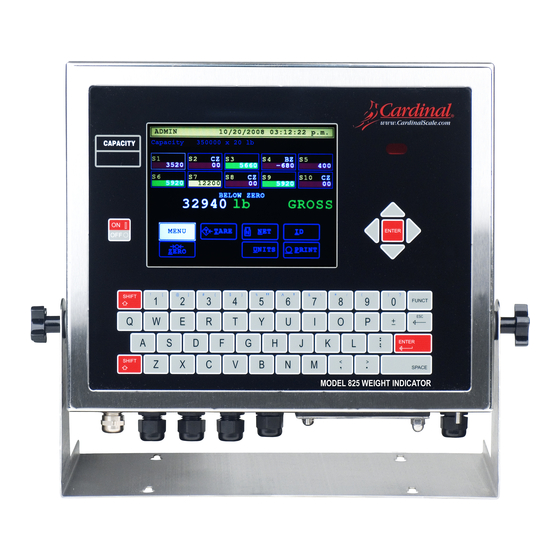
825
WEIGHT INDICATOR
INSTALLATION and TECHNICAL MANUAL
8545-M838-O1 Rev D
203 E. Daugherty, Webb City, MO 64870 USA
Printed in USA
09/12
Ph: 417-673-4631 Fax: 417-673-2153
www.cardinalscale.com
Technical Support: Ph: 866-254-8261 tech@cardet.com
8545-M838-O1 Rev D 825 Installation & Technical
1
Advertisement
Table of Contents

Related Manuals for Cardinal 825


Summary of Contents for Cardinal 825
- Page 1 WEIGHT INDICATOR INSTALLATION and TECHNICAL MANUAL 8545-M838-O1 Rev D 203 E. Daugherty, Webb City, MO 64870 USA Printed in USA 09/12 Ph: 417-673-4631 Fax: 417-673-2153 www.cardinalscale.com Technical Support: Ph: 866-254-8261 tech@cardet.com 8545-M838-O1 Rev D 825 Installation & Technical...
- Page 2 8545-M838-O1 Rev D 825 Installation & Technical...
-
Page 3: Table Of Contents
825-SIB (Scale Input Board) ........ - Page 4 Configure Tabs Page 7 ........Page 109 8545-M838-O1 Rev D 825 Installation & Technical...
- Page 5 PART IDENTIFICATION ......... . . Page 137 8545-M838-O1 Rev D 825 Installation & Technical...
- Page 6 8545-M838-O1 Rev D 825 Installation & Technical...
-
Page 7: Introduction
Configuration and upgrades can easily be performed in the field, while still maintaining the rigid control the most demanding installations require. This flexibility insures the Model 825 will be able to meet your weight indicating needs for years to come. -
Page 8: Fcc Compliance Statement
Nor can they assume responsibility for any damage to property or injury to persons occasioned from the procedures. Persons engaging the procedures do so entirely at their own risk. 8545-M838-O1 Rev D 825 Installation & Technical... -
Page 9: Specifications
1 ea ICAN port 4 ea Isolated Inputs and 4 ea Isolated Outputs port 1 ea 10/100 Base-T Ethernet port 2 ea USB A Host port 1 ea USB B Device port 8545-M838-O1 Rev D 825 Installation & Technical... -
Page 10: Features
Optional 9 additional option slots 825-SIB Scale Input Board 825-DIO Digital Input/Output (provides 8 configurable digital input and output lines) *These feature requires additional hardware and includes additional documentation. 8545-M838-O1 Rev D 825 Installation & Technical... -
Page 11: Application Software Used In Trade
(any port but COM1). This weight must be identical to that observed in step No. 2. 5. When developing application programs for use in Trade, you should check with the responsible metrology authorities to ensure that your program employs the proper safeguards. 8545-M838-O1 Rev D 825 Installation & Technical... -
Page 12: European Declaration Of Conformity
YY = last two digits of year ZZZ = sequential number The undersigned hereby declares, on behalf of Cardinal Scale Manufacturing Company of Webb City, Missouri, that the above-referenced product, to which this declaration relates, is in conformity with the... -
Page 13: Precautions
Make certain that the wrist strap ground lead is securely attached to an adequate ground. If you are uncertain of the quality of the ground, you should consult a licensed electrician. 8545-M838-O1 Rev D 825 Installation & Technical... -
Page 14: Site Preparation
SITE PREPARATION The Model 825 Weight Indicator is a precision weight-measuring instrument. As with any precision instrument, it requires an acceptable environment to operate at its peak performance and reliability. This section is provided to assist you in obtaining such an environment. -
Page 15: Electrical Power
SITE PREPARATION, CONT. Electrical Power The 825 has been designed to operate from 100 to 240 VAC at 50/60 Hz. Note that a special order is not required for operation at 230/240 VAC. CAUTION! - To avoid electrical hazard and possible damage to the indicator, DO NOT, under any circumstance, cut, remove, alter, or in any way bypass the power cord grounding prong. -
Page 16: Installation
NOTE: If your 825 indicator is already installed on a scale, the following information describing its installation does not apply. The Model 825 Indicator is housed in a stainless steel wall or desk-mount enclosure. The 825 gimbal may be mounted on a desk, table or other smooth, flat, horizontal surface or may be mounted on a wall. -
Page 17: Load Cell Cable Connection With Rfi Suppression
6 inches of the cable outer insulating jacket exposing the internal wires. Figure No. 3 5. Next, cut the shield wire so that it extends past the outer jacket approximately 3/4 inch. 8545-M838-O1 Rev D 825 Installation & Technical... - Page 18 6. Now, remove 1/4 inch of insulation from the end of each of the six wires (with sense leads) or four wires (without sense leads). 7. Remove the screw securing the 825 Scale Input Board (825-SIB) to the main PC board and CAUTION!
- Page 19 13. Referring to Figure No. 8, fold the shield wire back over the plastic insert and then insert the plastic insert (with the shield wire) into the gland connector. Figure No. 8 Shield Wire 8545-M838-O1 Rev D 825 Installation & Technical...
-
Page 20: Load Cell Cable Connection Without Rfi Suppression
7. To terminate a wire, loosen the screws in the terminal block and then insert the wire into the terminal opening. Tighten the screw to secure the wire in place. See Figure No. 7. 8. Repeat the procedure until all wires are in place. 8545-M838-O1 Rev D 825 Installation & Technical... -
Page 21: Load Cell Connections With Over 30 Feet Of Cable
+SENS, -SENS terminals of the load cell trim board (or the section seal trim board). For the 825-SIB to use the sense wires, the -SENS and +SENS jumpers J1 and J3 must be open (on one pin only) or removed. Refer to Figure No. 10 for the location of these jumpers. -
Page 22: I/O Cable Preparation And Installation
I/O Cable Preparation and Installation The 825 indicator may be connected to a printer to record weight and associated data or it may be connected to a remote display or even to a computer for transmission of weight data. The weight data may be transmitted on demand (pressing the PRINT key or on receipt of a command from the computer). - Page 23 INSTALLATION, CONT. RS232 Terminal Connections, Cont. 8545-M838-O1 Rev D 825 Installation & Technical...
-
Page 24: 20Ma Terminal Connections
COM2 requires J7 shunt installed on 20mA. TXB (Transmit B) 825 Active requires J3 installed. RXA (Receive A) RXB (Receive B) 825 Passive requires J3 removed. GND (Ground) Figure No. 12 Figure No. 13 8545-M838-O1 Rev D 825 Installation & Technical... -
Page 25: Rs485 Terminal Connections
TXB (Transmit B) 4-Wire requires J5 and J6 removed. RXA (Receive A) RXB (Receive B) Install J9 if 825 is last device on RS-485 bus. GND (Ground) Figure No. 14 Figure No. 15 8545-M838-O1 Rev D 825 Installation & Technical... -
Page 26: I/O (Input/Output) Terminal Connections - 825 Source Power
IN4 (Input 4) GND (Ground) IMPORTANT! Install J1 and J2 to allow the 825 to supply (source) 12VDC to a solid-state relay or other load (100 mA maximum). Figure No. 16 8545-M838-O1 Rev D 825 Installation & Technical... -
Page 27: I/O (Input/Output) Terminal Connections - External Power Source
For completely isolated outputs (when using an external power source), remove J1 and J2. Connect 12 to 24VDC to P16 pin 1 and GND to P16 pin 10. Load must still be 100 mA maximum. Figure No. 17 8545-M838-O1 Rev D 825 Installation & Technical... -
Page 28: Re-Installing The Rear Panel
Re-Installing the Rear Panel After all terminations have been made; 1. Reinstall the 825-SIB into the enclosure, taking care not to strike the board against the side of the 825 enclosure (see Figure No. 18 below). 2. Secure the 825-SIB to the main PC board with the screw removed earlier. -
Page 29: Main Pc Board
This board contains static sensitive components. Improper handling can result in damage to or destruction of the components or board. Such actual and/or consequential damage IS NOT covered under warranty. OUT4 OUT3 OUT2 OUT1 Figure No. 19 8545-M838-O1 Rev D 825 Installation & Technical... -
Page 30: Jumpers
Jumpers J1 and J2 – ISO I/O When installed, these jumpers allow the 825 indicator to supply (source) 12VDC to a solid- state relay or other load (100 mA maximum). To completely isolate the outputs when using an external power source, remove (or place on one pin only) J1 and J2. -
Page 31: Connectors
This jumper is for the RS-485 node termination selection. When installed, the RS-485 node is terminated indicating the 825 is the last device on the RS-485 bus. If the 825 is not the last device on the RS-485 bus (e.g., it is in the middle of the bus), then it must be un-terminated and jumper J9 must be open (on one pin only or removed). -
Page 32: Status Led's
D30 = Turned on to indicate that I/O Output 2 is active. D31 = Turned on to indicate that I/O Output 3 is active. D32 = Turned on to indicate that I/O Output 4 is active. 8545-M838-O1 Rev D 825 Installation & Technical... -
Page 33: Keypad Functions
Figure No. 20 ON I/OFF KEY Pressing the ON/OFF key when the 825 is off will turn the indicator ON. If the indicator is already on, you must press and hold the ON/OFF key for about four (4) seconds to turn the indicator OFF. -
Page 34: Navigation Keys
These keys are used to enter numeric data during the setup and calibration as well as during normal operation of the indicator. Note that they have alternate meanings. See the SHIFT and FUNCT keys 8545-M838-O1 Rev D 825 Installation & Technical... - Page 35 This key is used to enter a blank space during alphanumeric data input for setup and calibration as well as during normal operations. In addition, some parameters in setup and calibration require pressing the SPACE key to toggle its status or to step through the available selections. 8545-M838-O1 Rev D 825 Installation & Technical...
-
Page 36: Standard Indicator Keys
KEYPAD FUNCTIONS, CONT. Standard Indicator Keys This section describes the Standard Indicator keys (displayed on the Weight screen) along with their functions as programmed by the 825 menu selection. Standard indicator Refer to the actual indicator screen while reading this section. - Page 37 Pressing the A key will act as a pushbutton tare and will store the current Gross weight as the new tare weight and will switch the display to the Net weight mode. 8545-M838-O1 Rev D 825 Installation & Technical...
- Page 38 The display will return to the Weight screen, showing gross weight only. Also, if the weight is unstable (motion on the scale), pressing this key will momentarily display the message: Cannot print MOTION – The display will return to the Weight screen, showing gross weight only 8545-M838-O1 Rev D 825 Installation & Technical...
-
Page 39: Touch Screen Keys
Setting Date and Time section of this manual. MENU Pressing this key allows viewing or clearing the accumulators. For information on viewing or clearing the accumulators, refer to the Accumulators section of this manual. 8545-M838-O1 Rev D 825 Installation & Technical... - Page 40 5. With the Set ID screen displayed, press the SPACE key and then the ENTER key. 6. The display will return to the Weight screen with no ID shown below the ID key. 8545-M838-O1 Rev D 825 Installation & Technical...
- Page 41 The display will return to the Weight screen, showing gross weight only. Also, if the weight is unstable (motion on the scale), pressing this key will momentarily display the message: Cannot print MOTION – The display will return to the Weight screen, showing gross weight only 8545-M838-O1 Rev D 825 Installation & Technical...
-
Page 42: Annunciators
This is shown on the Weight screen to indicate that the 825 is in the Gross weight mode. This is shown on the Weight screen when the 825 is in the Net weight mode. Note that the screen will display the Gross, Tare and Net weights. -
Page 43: Setting The Date And Time
Weight screen. Otherwise, use the numeric keys to enter the seconds (0 to 59) and then press the ENTER key to save all of the new settings and return to the Weight screen. 8545-M838-O1 Rev D 825 Installation & Technical... -
Page 44: Setup And Calibration
Calibration Jumper (J10 – CAL INHIBIT) The calibration jumper J10 (CAL INHIBIT) is located on the edge of the 825 circuit board and can only be accessed by removing the rear panel of the indicator. See Figure No. 22 for the location of the calibration jumper. - Page 45 If you continue to try to perform calibration by selecting 2. Calibrate on the Scale 1 – Calibration Options screen, the display will show: CALIBRATION SEAL Calibration locked by hardware jumper Inside enclosure. Press any key 8545-M838-O1 Rev D 825 Installation & Technical...
- Page 46 ENTER key to save the new setting and return to the previous or next screen. Press the ESC/ (backspace) key to delete an incorrect value or character entered. 8545-M838-O1 Rev D 825 Installation & Technical...
-
Page 47: To Begin Setup And Calibration
SETUP AND CALIBRATION, CONT. To Begin Setup and Calibration 1. Press the ON/OFF key to turn on the 825. The display will perform a short self-test and then change to the Startup screen showing the software versions and status of the main board and option cards. - Page 48 Enter the password using the alphanumeric keys and then press the ENTER key to proceed with Calibration and Setup. NOTE: The 825 will arrive from the factory with the calibration access locked by the “login” and “password” prompts protection. The factory default login and password are “ADMIN”...
-
Page 49: Setup Menu
Otherwise, use the numeric keys to enter the day of the month (1 to 31) and then press the Down Arrow to advance to the next parameter or press the ENTER key to save the new setting and return to the previous screen. 8545-M838-O1 Rev D 825 Installation & Technical... - Page 50 Navigation Keys Left Arrow to return to the previous screen. Otherwise, use the numeric keys to enter the seconds (0 to 59) and then press the ENTER key to save the new setting and return to the previous screen. 8545-M838-O1 Rev D 825 Installation & Technical...
-
Page 51: Communication
With the Communication Menu displayed, press the 1 key or use the Navigation Keys to select (highlight) 1. Network and then press the ENTER key. The display will change to show the Setup Network screen. 8545-M838-O1 Rev D 825 Installation & Technical... - Page 52 IMPORTANT! The Netmask of the indicator should match the Netmask of the other computers on your network. The format for the Netmask is: ### . ### . ### . # (e.g., 255.255.252.0). 8545-M838-O1 Rev D 825 Installation & Technical...
- Page 53 Otherwise, press the SPACE key to toggle its status (select YES or NO) and then press the ENTER key to save the new setting and return to the previous screen. Weight Server: Yes Weight Server: No Startup Weight Server is Enabled. Startup Weight Server is Disabled. 8545-M838-O1 Rev D 825 Installation & Technical...
- Page 54 NOTE: The Telnet: parameter is for advanced users. Refer to the 825 Programmer documentation at “http://tech.825spectrum.com”. 8545-M838-O1 Rev D 825 Installation & Technical...
- Page 55 Otherwise, use the numeric keys to enter the stop bits and then press the ENTER key to save the new setting and return to the previous screen. Supported Stop Bits are 1 or 2. 8545-M838-O1 Rev D 825 Installation & Technical...
-
Page 56: Calibration
ENTER key to save the new setting and proceed to the next screen. The display will briefly show: Waiting for parameters Waiting for multi interval settings and then change to show the Scale 1 – Calibrations Options screen. Hardware calibration enabled 8545-M838-O1 Rev D 825 Installation & Technical... - Page 57 Custom label (up to 4 characters, e.g., Gal. for Gallons) and then press the Down Arrow to advance to the next parameter or press the ENTER key to save the new setting and return to the previous screen. 8545-M838-O1 Rev D 825 Installation & Technical...
- Page 58 Otherwise, use the alphanumeric keys to enter a new description for the Conv Units Custom Label (up to 5 characters, e.g., Litre for Litre) and then press the ENTER key to save the new setting and proceed to the next screen. 8545-M838-O1 Rev D 825 Installation & Technical...
- Page 59 ENTER key to save the new setting and proceed to the next screen. Allowable values are 0 to 5. 0 = ####### 2 = #####.## 4 = ###.#### 1 = ######.# 3 = ####.### 5 = ##.##### 8545-M838-O1 Rev D 825 Installation & Technical...
- Page 60 Moderate Filtering (Sample Rate = 1) Moderate Custom Filtering (Additional Parameters Displayed) Custom NOTE: When Custom Filtering (Custom) has been selected, the following parameters, TYPE:, Filter Break: and Filter Value: will be displayed. 8545-M838-O1 Rev D 825 Installation & Technical...
- Page 61 Otherwise, use the numeric keys to enter the value for the filter value and then press the ENTER key to save the new setting and proceed to the next screen. Allowable values are 0 to 255. 8545-M838-O1 Rev D 825 Installation & Technical...
- Page 62 EXAMPLE: 20,000 x 10lb capacity scale with 800lb variation in the weight display. Filter Break: 80 4. If stability is unacceptable with any setting of Filter Value:, reduce the Sample Rate: and/or increase the Filter Break: range setting for increased filtering. 8545-M838-O1 Rev D 825 Installation & Technical...
- Page 63 For example, selecting 2 for the Num Cal Pts parameter, you would have a total of three calibration points, the zero (no load) weight and two calibrations points that could correspond to a mid-point weight and the test (load) weight. 8545-M838-O1 Rev D 825 Installation & Technical...
- Page 64 9600 baud, 8 data bits, no parity bits and 1 stop bit. Note that the serial port communication parameters can be change in the Communication setup. The data will be sent out at a rate of 2 times per second. 8545-M838-O1 Rev D 825 Installation & Technical...
- Page 65 (no load and two load points with different weights). If only two calibration points (no load and load) are used, the COEFF option will NOT be added to the Fine Span screen. 8545-M838-O1 Rev D 825 Installation & Technical...
- Page 66 ENTER key, if incorrect values have been entered for Low Interval Capacity: and Middle Interval Value:. To change the settings, press the /ESC key to return to the Intervals: screen. 8545-M838-O1 Rev D 825 Installation & Technical...
- Page 67 ENTER key, if incorrect values have been entered for Low Interval Capacity:, Middle Interval Value:, Middle Interval Capacity: and High Interval Value:. To change the settings, press the /ESC key to return to the Intervals: screen. 8545-M838-O1 Rev D 825 Installation & Technical...
-
Page 68: Totalizer Function
Down Arrow to proceed to the next scale. Repeat the above steps for each scale to be included in the Totalize and then press the ENTER key to save the new settings and proceed to the next parameter . 8545-M838-O1 Rev D 825 Installation & Technical... - Page 69 Conv Units: parameter will be shown. If the setting displayed is acceptable, proceed to the next parameter. Otherwise, press the SPACE key to select the Conv Units and then press the ENTER key to save the new setting and proceed to the next screen. 8545-M838-O1 Rev D 825 Installation & Technical...
- Page 70 Moderate Filtering (Sample Rate = 1) Moderate Custom Filtering (Additional Parameters Displayed) Custom NOTE: When Custom Filtering (Custom) has been selected, the following parameters, TYPE:, Filter Break: and Filter Value: will be displayed. 8545-M838-O1 Rev D 825 Installation & Technical...
- Page 71 Otherwise, use the numeric keys to enter the value for the filter value and then press the ENTER key to save the new setting and proceed to the next screen. Allowable values are 0 to 255. 8545-M838-O1 Rev D 825 Installation & Technical...
- Page 72 For example, selecting 2 for the Num Cal Pts parameter, you would have a total of three calibration points, the zero (no load) weight and two calibrations points that could correspond to a mid-point weight and the test (load) weight. 8545-M838-O1 Rev D 825 Installation & Technical...
- Page 73 Zero Limit: Yes Zero Limit: No Select Yes to limit push button zero Full capacity (no limit on push and zero tracking to ± 2% of capacity button zero and zero tracking) 8545-M838-O1 Rev D 825 Installation & Technical...
- Page 74 (no load and two load points with different weights). If only two calibration points (no load and load) are used, the COEFF option will NOT be added to the Fine Span screen. 8545-M838-O1 Rev D 825 Installation & Technical...
- Page 75 ENTER key, if incorrect values have been entered for Low Interval Capacity: and Middle Interval Value:. To change the settings, press the /ESC key to return to the Intervals: screen. 8545-M838-O1 Rev D 825 Installation & Technical...
- Page 76 ENTER key, if incorrect values have been entered for Low Interval Capacity:, Middle Interval Value:, Middle Interval Capacity: and High Interval Value:. To change the settings, press the /ESC key to return to the Intervals: screen. 8545-M838-O1 Rev D 825 Installation & Technical...
- Page 77 With the Setup Scale Number screen displayed, use the numeric keys to enter the number for the scale to calibrate or press the Down Arrow and then press the ENTER key to select the scale to calibrate. 8545-M838-O1 Rev D 825 Installation & Technical...
-
Page 78: Calibration Methods
SETUP AND CALIBRATION, CONT. Calibration Methods The 825 has two methods to enter the calibration procedure. One method is performed after entering the calibration setup parameters. The other method is selected from the Setup Menu screen and skips entering the calibration setup parameters. - Page 79 When this step has been completed, the display will change to show the Scale 1 – Fine Span screen. NOTE: If Span Adjustment is required, proceed to the FINE SPAN ADJUSTMENT. 8545-M838-O1 Rev D 825 Installation & Technical...
- Page 80 Down Arrow to advance to the next parameter. WARNING! Changing the Linear Coefficient or the 2nd Order Coeff will affect the indicator's ability to display the proper weight. Please consult the factory before making any changes. 8545-M838-O1 Rev D 825 Installation & Technical...
- Page 81 Scale 1 – Fine Span screen. Otherwise, use the numeric keys to enter a new tweak weight and then press the ENTER key to return to the Scale 1 – Fine Span screen. 8545-M838-O1 Rev D 825 Installation & Technical...
-
Page 82: Preferences
PREFERENCES 1. Press the ON/OFF key to turn on the 825. The display will perform a short self-test and then change to the Startup screen showing the software versions and status of the option cards. 2. Press the Navigation Keys Down Arrow to “advance” to (highlight) the Legal metrology information / Setup menu option and then press the ENTER key or press the 3 key to select the Legal metrology information / Setup option. - Page 83 Otherwise, use the alphanumeric keys to specify the text for a.m. time and then press the Down Arrow to advance to the next parameter or press the ENTER key to save the new setting and return to the previous screen. 8545-M838-O1 Rev D 825 Installation & Technical...
- Page 84 Navigation Keys Left Arrow to return to the previous screen. Otherwise, use the alphanumeric keys to specify the text for p.m. time and then press the ENTER key to save the new setting and return to the previous screen. 8545-M838-O1 Rev D 825 Installation & Technical...
-
Page 85: Sound Settings
Press and hold (about 4 seconds) the ON/OFF key to turn off the indicator. Wait a few seconds and then press it again to turn the indicator back ON. The sound settings have been saved and are now effective. 8545-M838-O1 Rev D 825 Installation & Technical... -
Page 86: Operators
Administrator operator. 1. Press the ON/OFF key to apply power to the 825. The display will perform a short self-test and then change to the Startup screen showing the software versions and status of the option cards. -
Page 87: List Operators
Login: Use the alphanumeric keys to enter a login (name) for the operator (up to 8 characters, e.g., CARDINAL) and then press the Down Arrow to advance to the next parameter. Password: Use the alphanumeric keys to enter a password for the operator (up to 8 characters) and then press the ... - Page 88 Down Arrow to proceed to the next parameter. Otherwise, press the SPACE key (or the Y or N key) to toggle between the Yes and No and then press the Down Arrow to advance to the next parameter. 8545-M838-O1 Rev D 825 Installation & Technical...
- Page 89 Otherwise, press the SPACE key (or the Y or N key) to toggle between the Yes and No and then press the ENTER key to save the settings and return to the previous screen. 8545-M838-O1 Rev D 825 Installation & Technical...
-
Page 90: Edit Operators
Edit Operator screen and prompt for the operator login (name). 2. Enter the operator login and then press the ENTER key. The display will change to the Edit Operator screen and show the current settings. 8545-M838-O1 Rev D 825 Installation & Technical... - Page 91 If the setting displayed is acceptable, proceed to the next parameter. Otherwise, press the SPACE key (or the Y or N key) to toggle between the Yes and No and then press the Down Arrow to advance to the next parameter. 8545-M838-O1 Rev D 825 Installation & Technical...
- Page 92 Otherwise, press the SPACE key (or the Y or N key) to toggle between the Yes and No and then press the ENTER key to save the settings and return to the previous screen. 8545-M838-O1 Rev D 825 Installation & Technical...
-
Page 93: Delete Operators
5. The display will change to show the Setup Operators screen. All settings for that operator login have been deleted. 6. Otherwise, press the N key (for No) and then press the ENTER key to return to the Setup Operators screen. 8545-M838-O1 Rev D 825 Installation & Technical... -
Page 94: Set Default Operators
OPERATORS, CONT. 5. Set Default Operator The Set Default Operator screen allows to you to select which operator login the 825 will use when it is first turned on. With the Setup Operators screen displayed, press the 5 key or use the Navigation Keys to select (highlight) 5. -
Page 95: Configuration
Ticket Settings and Configure the application menu. To Begin Configuration 1. Press the ON/OFF key to apply power to the 825. The display will perform a short self- test and then change to the Startup screen showing the software versions and diagnostics of the option cards. - Page 96 CONFIGURATION, CONT. Application Menu OS Version 1.12.009 Configuration File Manager By Cardinal By Cardinal Slide Show By Cardinal << Prev IP: 127.0.0.1 8545-M838-O1 Rev D 825 Installation & Technical...
-
Page 97: Calibration Touch Screen
1. With the Touch screen calibration screen displayed, the target, a plus sign “” will be shown in the upper left corner of the display. Touch screen calibration Touch target or press ESC to quit 8545-M838-O1 Rev D 825 Installation & Technical... -
Page 98: Show Touch Screen Tracking
Note that the screen will be blank except for a message (Press [ESC] exit) at the top center of the display. Press [ESC] exit 8545-M838-O1 Rev D 825 Installation & Technical... - Page 99 2. The target, a plus sign “” will move to each location touched. Press [ESC] exit The sign indicates the screen was touched here 3. After checking several locations on the screen, press the ESC key to return to the Configuration screen. 8545-M838-O1 Rev D 825 Installation & Technical...
-
Page 100: Set Color Setting
ENTER key. The screen will change to a white background with black characters on it. Black on white After setting the screen colors, press the ESC key to return to the Configuration screen. 8545-M838-O1 Rev D 825 Installation & Technical... -
Page 101: Configure Weight Server
The display will change to show the Select TCP/IP Server screen. Select TCP/IP Server Num Sc Type Port 1. 0 Custom 1100 2. 1 On Demand 1101 ** Add Server ** 8545-M838-O1 Rev D 825 Installation & Technical... - Page 102 Otherwise, use the numeric keys to enter the scale number for the server to use and then press the Down Arrow to advance to the next parameter or press the ENTER key to save the new setting and return to the previous screen. 8545-M838-O1 Rev D 825 Installation & Technical...
- Page 103 Setup TCP/IP Server 3 screen. The setup parameters for adding an additional TCP/IP Server are the same as the setup for TCP/IP Server 1. Refer to the Setup TCP/IP Server 1 parameters. 8545-M838-O1 Rev D 825 Installation & Technical...
-
Page 104: Configure Serial Ports
If Yes is selected for Enable:, the following additional parameters will be shown (below the Enable: parameter) and requires data to be entered. Otherwise, press the ENTER key to return to the Select Serial screen. 8545-M838-O1 Rev D 825 Installation & Technical... - Page 105 Setup Serial 2 screen. The setup parameters for adding an additional Serial port are the same as the setup for Serial 1. Refer to the Setup Serial 1 parameters. 8545-M838-O1 Rev D 825 Installation & Technical...
-
Page 106: Configuration Of Weight Server Complete
ENTER key or use the Navigation Keys to select (highlight) the application to run and then press the ENTER key. 5. The application will be loaded and the display will change to the application screen. 8545-M838-O1 Rev D 825 Installation & Technical... -
Page 107: Ticket Settings
Otherwise, use the alphanumeric keys to enter the form name to use (up to 8 characters) and then press the Down Arrow to advance to the next parameter or press the ENTER key to save the new setting and return to the previous screen. 8545-M838-O1 Rev D 825 Installation & Technical... - Page 108 Special 4 Special 5 Special 6 If Default is selected, the display will change to the Configure tabs page 1 screen. This is the screen to input the Print Tabs Settings. 8545-M838-O1 Rev D 825 Installation & Technical...
-
Page 109: Print Tab Setting
Label. Use the alphanumeric keypad for the Label characters. Press the Down Arrow to advance to the next parameter. NOTE: Use the UP Arrow key to “backup” to the previous coordinate or parameter. 8545-M838-O1 Rev D 825 Installation & Technical... -
Page 110: Configure Tabs Page
Label. Use the alphanumeric keypad for the Label characters. Press the Down Arrow to advance to the next parameter. NOTE: Use the UP Arrow key to “backup” to the previous coordinate or parameter. 8545-M838-O1 Rev D 825 Installation & Technical... -
Page 111: Configure Tabs Page
Label. Use the alphanumeric keypad for the Label characters. Press the Down Arrow to advance to the next parameter. NOTE: Use the UP Arrow key to “backup” to the previous coordinate or parameter. 8545-M838-O1 Rev D 825 Installation & Technical... -
Page 112: Configure Tabs Page
Label. Use the alphanumeric keypad for the Label characters. Press the Down Arrow to advance to the next parameter. NOTE: Use the UP Arrow key to “backup” to the previous coordinate or parameter. 8545-M838-O1 Rev D 825 Installation & Technical... -
Page 113: Configure Tabs Page
Down Arrow key to advance to the next line. Press the Down Arrow to advance to the next parameter. NOTE: Use the UP Arrow key to “backup” to the previous coordinate or parameter. 8545-M838-O1 Rev D 825 Installation & Technical... -
Page 114: Configure Tabs Page
NOTE: Use the UP Arrow key to “backup” to the previous coordinate or parameter. When the description for all lines of the Header and Footer have been entered, press the ENTER key to save the new settings and return to the Configure Ticket screen. 8545-M838-O1 Rev D 825 Installation & Technical... -
Page 115: Configure Tabs Page
<0xFE> would output the character FE hex (254 decimal). When all Begin and End Print Codes have been entered, press the ENTER key to save the new settings and return to the Configure Ticket screen. 8545-M838-O1 Rev D 825 Installation & Technical... -
Page 116: Configure Application Menu
ENTER key to save the new setting and return to the previous screen. Available applications are: None Truck / ID Storage DFC Batcher Checkweigher Highway Weigh Station Multi Scale Multi Scale (EIP) 8545-M838-O1 Rev D 825 Installation & Technical... - Page 117 Slide Show: Yes Slide Show: No Select Yes to include the Slide Show The Slide Show selection is not selection on the Application Menu. displayed on the Application Menu. 8545-M838-O1 Rev D 825 Installation & Technical...
- Page 118 (countdown timer on the Application Menu screen) and then press the ENTER key to save the new setting and return to the previous screen. Supported countdown times are 2 through 90 seconds. 8545-M838-O1 Rev D 825 Installation & Technical...
-
Page 119: Set Factory Defaults
E R A S E one letter per screen and then press the ENTER key on the last screen. NOTE: You can cancel the operation at any time by pressing any other key. 8545-M838-O1 Rev D 825 Installation & Technical... - Page 120 Otherwise, press any other key to cancel and return to the Configuration screen. Press the E key to proceed to the next Confirm Set Defaults screen. Otherwise, press any other key to cancel and return to the Configuration screen. 8545-M838-O1 Rev D 825 Installation & Technical...
- Page 121 CAN press any other key to cancel erasing the indicator memory and setting the indicator back to the factory defaults. The display will show Cancelled and return to the Configuration screen. 8545-M838-O1 Rev D 825 Installation & Technical...
-
Page 122: Application Menu Screen
(highlight) Next >> and then press the ENTER key. The display will change to show the Application Menu screen for the additional applications. Application Menu OS Version 1.12.009 Configuration File Manager By Cardinal By Cardinal Slide Show By Cardinal << Prev IP: 127.0.0.1 8545-M838-O1 Rev D 825 Installation & Technical... -
Page 123: Troubleshooting
TROUBLESHOOTING The 825 is equipped with diagnostic software that tests various portions of the indicator's circuitry and verifies proper operation. Should a problem be detected, an error or status message will be displayed alerting the operator to that condition. The following lists these status messages and errors and their meaning. - Page 124 Operator not allowed to chg units The current operator login does not permit changing the current unit selection. Operator not allowed to print The current operator login does not permit using the print function. 8545-M838-O1 Rev D 825 Installation & Technical...
-
Page 125: Error Codes
Error Codes (During View Audit Trail) Mnbd reports 01 EEPROM corrupt The checksum failed. There may be a problem with the EEPROM chip on the mainboard. 8545-M838-O1 Rev D 825 Installation & Technical... -
Page 126: During Add Operator
An attempt was made to add a new operator when all operator login spaces are filled. The Model 825 supports a total of eight operators. One operator is the Administrator (with full access to all functions and features). The remaining seven are for users and can be configured to allow or prevent access to various functions and features. -
Page 127: Diagnostics
2. The display will perform a short self-test and then change to the Startup screen. Note that when the 825 is initially started, a countdown starting at 7 seconds will appear to the right of 1. Application program. When the countdown is complete, the application program will automatically start. -
Page 128: To Begin Diagnostics
With the Setup Menu displayed, press the 6 key or use the Navigation Keys to select (highlight) 6. Diagnostics and then press the ENTER key. The display will change to show the Diagnostics Menu screen. 8545-M838-O1 Rev D 825 Installation & Technical... - Page 129 With the Diagnostics Menu displayed, press the 2 key or use the Navigation Keys to select (highlight) 2. Mainboard I/O test and then press the ENTER key. The display will change to show the Test Mainboard I/O screen. 8545-M838-O1 Rev D 825 Installation & Technical...
- Page 130 Test NOR Flash screen. WARNING! Test NOR Flash Performing the test will ERASE the boot-loader and operating system. This test must be performed only at properly equipped programming stations. 8545-M838-O1 Rev D 825 Installation & Technical...
-
Page 131: Fine Span Adjustment
1. Press the ON/OFF key to turn on the 825. The display will perform a short self-test and then change to the Startup screen showing the software versions and diagnostics of the option cards. - Page 132 If the setting displayed is acceptable, press the Down Arrow to advance to the Tweak weight: parameter. Otherwise, use the numeric keys to enter the tweak high weight and then press the Down Arrow to advance to the next parameter. 8545-M838-O1 Rev D 825 Installation & Technical...
- Page 133 Scale 1 – Fine Span screen. Otherwise, use the numeric keys to enter a new tweak weight and then press the ENTER key to return to the Scale 1 – Fine Span screen. 8545-M838-O1 Rev D 825 Installation & Technical...
-
Page 134: Event Counters
EVENT COUNTERS A Category 1 Event Counter is provided on the 825 with two counters that increment when a change is made to features that are required by NTEP or OIML to be sealed. One counter is designated for calibration parameters and one is designated for configuration changes as required in NCWM Publication 14, 2007. - Page 135 To return to the Weight Screen and resume normal weighing operations, with the Legal metrology / Setup screen displayed, press the Navigation Keys Left Arrow to return to the Startup screen. 8545-M838-O1 Rev D 825 Installation & Technical...
-
Page 136: Certifications / Id Information
CERTIFICATIONS / ID INFORMATION To View the Certifications / ID Information 1. Press the ON/OFF key to turn on the 825. A self-test will be performed showing the software versions and status of the option cards and then display the Startup screen. - Page 137 To return to the Weight Screen and resume normal weighing operations, with the Legal metrology / Setup screen displayed, press the Navigation Keys Left Arrow to return to the Startup screen. 8545-M838-O1 Rev D 825 Installation & Technical...
-
Page 138: Electronic Talley Roll (Etr) File
Note that when its capacity is reached, the newest transaction will replace the oldest. To View the Electronic Talley Roll (ETR) File 1. Press the ON/OFF key to apply power to the 825. The display will perform a short self- test and then change to the Startup screen showing the software versions and diagnostics of the option cards. - Page 139 (highlight) Configure Weight Server and then press the ENTER key. The display will change to show the Configure Weight Server screen. Configure Weight Server Configure TCP/IP Server Configure Serial Ports Electronic Talley Roll 8545-M838-O1 Rev D 825 Installation & Technical...
- Page 140 SPACE key to select the Output port. Available output ports are: COM1-RS232 COM1-Bluetooth COM2 COM3 USB-PRT1 USB-PRT2 USB-PRT3 USB-PRT4 USB-PRT5 USB-PRT6 When the desired output port has been selected, press the ENTER key to proceed to the ETR Report screen. 8545-M838-O1 Rev D 825 Installation & Technical...
- Page 141 With the Application Menu displayed, press the number key of the application to run or use the Navigation Keys to select (highlight) the application to run and then press the ENTER key. The display will change to show the Weight screen. Normal weighing operations can now resume. 8545-M838-O1 Rev D 825 Installation & Technical...
-
Page 142: Lead And Wire Security Seal Installation
LEAD AND WIRE SECURITY SEAL INSTALLATION If your Model 825 indicator is used in a commercial application and your local metrology laws require the use of physical sealing, a lead and wire security seal can be installed to prevent the rear panel from being removed from the indicator. -
Page 143: Part Identification
PART NUMBER DESCRIPTION 6013-0297 NUT #10-32 HEX 6024-0037 WASHER LOCK HELICAL SP #10 REG SS 6610-5002 GROUND LUG L-35 8545-C860-08 825 GASKET SET 593GR986 SERIAL TAG ASSY. 5930-B124-08 LABEL: ETL FOR 825 8545-M838-O1 Rev D 825 Installation & Technical... - Page 144 QTY. PART NUMBER DESCRIPTION 6980-1030 POWER CORD 18/3 SJTW CEE 6.3 FT. 8545-C822-0A BEZEL WELDMENT 8545-D810-08 KEYPAD: 825 INDICATOR 593GR986 SERIAL TAG ASSY. 6980-0250 POWER CORD EURO ( 8545-D853-08 KEYPAD: C.A.T. INDICATOR 8545-M838-O1 Rev D 825 Installation & Technical...
- Page 145 PART IDENTIFICATION (Front View) 8545-M838-O1 Rev D 825 Installation & Technical...
- Page 146 WASHER FLAT #6 NEOPRENE BACKING SS 6680-0004 WASHER LOCK INT TOOTH #6 TYPE A Z-PL 6680-0220 SPACER #6 x .875 NYLON 8545-C834-0A POWER SUPPLY ASSEMBLY 8545-D835-1A SUB-CHASSIS ASSEMBLY – LED 6610-5084 TERMINAL BLOCK, 3 POS. 8545-M838-O1 Rev D 825 Installation & Technical...
- Page 147 PART IDENTIFICATION (Rear – Inside View) NOTE: The ground wire for the power supply is attached to the enclosure wall at the ground lug located under the power supply housing as show. 8545-M838-O1 Rev D 825 Installation & Technical...
- Page 148 8545-B847-0A PCB ASS'Y 825 LED BACKLIGHT CONTROLLER 8545-D801-0A PCB: OPERATOR INTERFACE, 825 INDICATOR 8545-C803-0A PCB: SCALE INPUT, 825 INDICATOR 8545-D800-0A PCB: CONTROLLER, 825 INDICATOR 8545-D802-08 BOARD MOUNT BRACKET 8545-B812-08 BACKLIGHT INVERTER CABLE 8545-M838-O1 Rev D 825 Installation & Technical...
- Page 149 PART IDENTIFICATION (ITEM # 19, 8545-D835-1A, SUB-CHASSIS ASSEMBLY – LED) 8545-M838-O1 Rev D 825 Installation & Technical...
- Page 150 (Mounting Touch Screen Cable) NOTE: Tape must extend past the edge of enclosure as shown. ITEM # QTY. PART NUMBER DESCRIPTION 8545-D897-0A FRONT ENCLOSURE WELDMENT 6710-0030 TAPE, DBL. SIDED 0.5” WIDE 8545-M838-O1 Rev D 825 Installation & Technical...
- Page 151 CONN GLAND .160-.310 GRIP .60 MTG NICKEL 6610-2248 CONN GLAND .187-.312 GRIP .599 MTG BLK 6540-1104 HOLE PLUG, 0.173-0.240 6560-0311 PLUG RUBBER 734506 6610-2081 CONN GLAND .179-.470 GRIP .875 MTG BLK 6910-0171 NUT CONDUIT 1/2 LOCK 8545-M838-O1 Rev D 825 Installation & Technical...
- Page 152 (Rear View) ITEM # QTY. PART NUMBER DESCRIPTION 6013-0433 NUT #10-32 HEX ACORN LOCK SS 8545-B813-08 ACCESS PLATE 8545-C860-08 825 GASKET SET 8545-C896-08 REAR PANEL 8200-B026-08 NUT #10-32 HEX ACORN LOCK, DRILLED, SS 8545-M838-O1 Rev D 825 Installation & Technical...
- Page 153 STATEMENT OF LIMITED WARRANTY WARRANTY TERMS Cardinal Scale Manufacturing Company warrants the equipment we manufacture against defects in material and workmanship. The length and terms and conditions of these warranties vary with the type of product and are summarized below:...
- Page 154 This warranty sets forth the extent of our liability for breach of any warranty or deficiency in connection with the sale or use of our product. Cardinal will not be liable for consequential damages of any nature, including but not limited to loss of profit, delays or expenses, whether based on tort or contract.
- Page 156 8545-M838-O1 Rev D 825 Installation & Technical...
Need help?
Do you have a question about the 825 and is the answer not in the manual?
Questions and answers