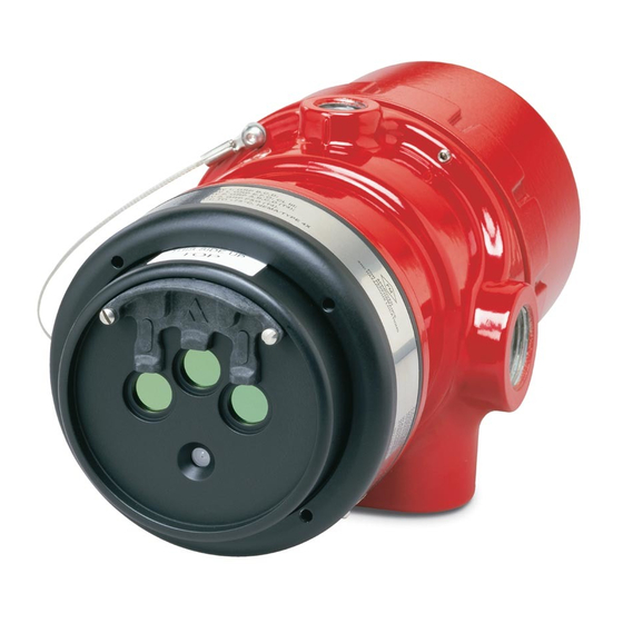
Det-Tronics Protect-IR X3302 Instructions Manual
Multispectrum ir flame detector
Hide thumbs
Also See for Protect-IR X3302:
- Instructions manual (39 pages) ,
- Addendum (16 pages) ,
- Instructions manual (36 pages)
Table of Contents

Related Manuals for Det-Tronics Protect-IR X3302


Summary of Contents for Det-Tronics Protect-IR X3302
- Page 1 Instructions 95-8576 Protect•IR ® Multispectrum IR Flame Detector X3302 Detector Electronics Corporation 6901 West 110th Street • Minneapolis, Minnesota 55438 USA 4/05 95-8576 Tel: 952.941.5665 or 800.765.3473 • Fax: 952.829.8750...
-
Page 2: Table Of Contents
Table Of Contents DESCRIPTION ....................1 Outputs ....................2 LED .......................2 Optical Integrity (Oi) ................2 Communication ..................3 Data Logging..................3 Integral Wiring Compartment ..............3 GENERAL APPLICATION INFORMATION ..........3 Response Characteristics ..............3 Important Application Considerations ...........3 IMPORTANT SAFETY NOTES ..............4 INSTALLATION....................4 Detector Positioning................4 Detector Orientation................5 Protection Against Moisture Damage ...........5 Wiring Procedure ..................6 Setting Device Network Addresses (EQP Model Only) ......12... -
Page 3: Description
TRONICS ® INSTRUCTIONS Protect•IR ® Multispectrum IR Flame Detector X3302 IMPORTANT Be sure to read and understand the entire instruction manual before installing or operating the flame detection system. Any deviation from the recommendations in this manual may impair system performance and compromise safety. ATTENTION The X3302 includes the Automatic Optical Integrity (o i ) feature —... -
Page 4: Outputs
LON/SLC Output The EQP model is designed for use exclusively with The Fire Alarm relay has redundant terminals and the Det-Tronics Eagle Quantum Premier system. The normally open / normally closed contacts, normally detector communicates with the system controller over... -
Page 5: Communication
Magnetic o i / Manual o i DATA LOGGING The detector also incorporates both magnetic o i and Data logging capability is also provided. Status manual o i features that provide the same calibrated test conditions such as normal, power down, general and o i as the automatic o i , and in addition actuates the Alarm faults, pre-alarm, fire alarm, time and temperature are relay to verify output operation for preventive... -
Page 6: Important Safety Notes
EMI/RFI Interference INSTALLATION The X3302 is resistant to interference by EMI and RFI, DETECTOR POSITIONING and is EMC Directive compliant. It will not respond to a 5 watt walkie-talkie at distances greater than 1 foot. Do Detectors should be positioned to provide the best not operate a walkie-talkie within 1 foot of the X3302. -
Page 7: Detector Orientation
PROTECTION AGAINST MOISTURE DAMAGE It is important to take proper precautions during installation to ensure that moisture will not come in CENTER AXIS OF DETECTOR contact with the electrical connections or components FIELD OF VIEW of the system. The integrity of the system regarding moisture protection must be maintained for proper operation and is the responsibility of the installer. -
Page 8: Wiring Procedure
WIRING PROCEDURE Detector Mounting Install the swivel mounting bracket assembly on the wall. Wire Size and Type The installation surface should be free of vibration and The system should be wired according to local codes. suitable to receive 1/4 inch (M6) screws with a length of The wire size selected should be based on the number at least 1 inch (25 mm), and have sufficient capacity to of detectors connected, the supply voltage and the... - Page 9 2. Check all field wiring to be sure that the proper connections have been made. IMPORTANT Do not test any wiring connected to the detector with a meg-ohmmeter. Disconnect wiring at the detector before checking system wiring for continuity. 3. Make the final sighting adjustments and ensure that the mounting bracket hardware is tight.
- Page 10 X3302 DETECTOR FIRE ALARM PANEL 4-20 mA + 4-20 mA – SPARE 4-20 mA + REF 4-20 mA – REF SPARE COM FIRE 2 COM AUX COM FIRE N.O. FIRE 2 N.O. AUX N.O. FIRE E.O.L. DEVICE 4 N.C. FIRE 2 N.C.
- Page 11 X3302 IR DETECTOR X3302 IR DETECTOR 600 Ω MAX 4-20 mA + 4-20 mA – 600 Ω MAX 4-20 mA + 4-20 mA – AT 24 VDC AT 24 VDC 4-20 mA – REF 4-20 mA + REF – – 4 TO 20 mA 4 TO 20 mA 24 VDC...
- Page 12 EQP Model 5. Check all field wiring to be sure that the proper connections have been made. 1. Connect external wires to the appropriate terminals inside the device junction box. (See 6. Replace the device cover. Figure 13 for terminal identification.) 7.
- Page 13 CH 1 CH 2 CH 3 CH 4 CH 5 CH 6 CH 7 CH 8 RELAY 2 RELAY 3 RELAY 4 RELAY 1 DIGITAL INPUTS RELAY 5 RELAY 6 RELAY 7 RELAY 8 95-8576...
-
Page 14: Setting Device Network Addresses (Eqp Model Only)
ADDRESS SWITCHES SENSOR MODULE REMOVED FROM HOUSING A2191 Figure 15—Location of Address Switches SETTING DEVICE NETWORK ADDRESSES disassembly of the device. Always observe (EQP Model Only) precautions for handling electrostatic sensitive devices. Overview of Network Addresses The address number is binary encoded with each Each device on the LON must be assigned a unique switch having a specific binary value with switch 1 address. -
Page 15: Startup Procedure
Important: Disconnect 5. Verify that all detectors in the system are properly wiring at the detector before checking system aimed at the area to be protected. (The Det-Tronics wiring for continuity. Q1201C Laser Aimer is recommended for this purpose.) -
Page 16: Cleaning Procedure
Disable any extinguishing equipment that is connected to the unit to prevent unwanted actuation. To clean the windows and o i plate, use Det-Tronics NOTE window cleaner (part number 001680-001) and a soft If the o i plate is removed, be sure to install the cloth, cotton swab or tissue and refer to the following original o i plate. -
Page 17: Features
FEATURES POWER UP TIME— Fault indication clears after 0.5 second; device is ready • Unequaled false alarm rejection. to indicate an alarm condition after 30 seconds. • Responds to a fire in the presence of modulated OUTPUT RELAYS— blackbody radiation (i.e. heaters, ovens, turbines) Fire Alarm relay, Form C, 5 amperes at 30 vdc: without false alarm. - Page 18 ENCLOSURE MATERIAL— Increased Safety Model Copper-free aluminum (red-painted) or 316 stainless 0539 II 2 GD steel. EEx de IIC T5–T6 DEMKO 04 ATEX 137104 T6 (T = –55°C to +60°C). VIBRATION— Conformance per FM 3260: 2000, MIL-STD 810C (Curve T5 (T = –55°C to +75°C).
-
Page 19: Replacement Parts
REPLACEMENT PARTS ORDERING INFORMATION The detector is not designed to be repaired in the field. When ordering, please specify: If a problem should develop, refer to the Troubleshooting section. If it is determined that the X3302 IR Flame Detector problem is caused by an electronic defect, the device must be returned to the factory for repair. -
Page 20: Appendix
APPENDIX FM Approvals Description and Performance Report THE FOLLOWING ITEMS, FUNCTIONS AND OPTIONS DESCRIBE THE FM APPROVAL: • Explosion-proof for Class I, Div. 1, Groups B, C and D Hazardous (Classified) Locations per FM 3615. • Dust-ignition proof for Class II/III, Div. 1, Groups E, F and G Hazardous (Classified) Locations per FM 3615. •... - Page 21 FM Approvals Description and Performance Report – Continued RESPONSE CHARACTERISTICS: Very High Sensitivity Fuel Size/ Distance Average Response Time Flow Rate feet (m) (seconds) Hydrogen 24 inch plume/ 100 (30.5) 100 SLPM* Methanol 1 x 1 foot 70 (21.3) Standard Liters Per Minute (Standard conditions defined as +25°C and 14.696 PSIA) FIELD OF VIEW: Very High Sensitivity Fuel...
- Page 22 FM Approvals Description and Performance Report – Continued RESPONSE CHARACTERISTICS IN THE PRESENCE OF FALSE ALARM SOURCES: Very High Sensitivity Unmodulated Source False Alarm Source Distance Fire Source Distance Average Response Time Unmodulated feet (m) Hydrogen feet (m) (seconds) Two 34 w fluorescent lamps 5 (1.5) 100 SLPM 100 (30.5)
- Page 23 FM Approvals Description and Performance Report – Continued HIGH RESOLUTION FIELD OF VIEW 0° 0° 15° 15° 15° 15° 70 ft 100 ft 30° 30° 30° 30° 90 ft 60 ft 80 ft 45° 45° 45° 45° 50 ft 70 ft 60 ft 40 ft 50 ft...
- Page 24 Printed in USA Detector Electronics Corporation 6901 West 110th Street • Minneapolis, Minnesota 55438 USA Tel: 952.941.5665 or 800.765.3473 • Fax: 952.829.8750...