Table of Contents
Advertisement
Quick Links
Advertisement
Table of Contents

Related Manuals for Det-Tronics X5202


Summary of Contents for Det-Tronics X5202
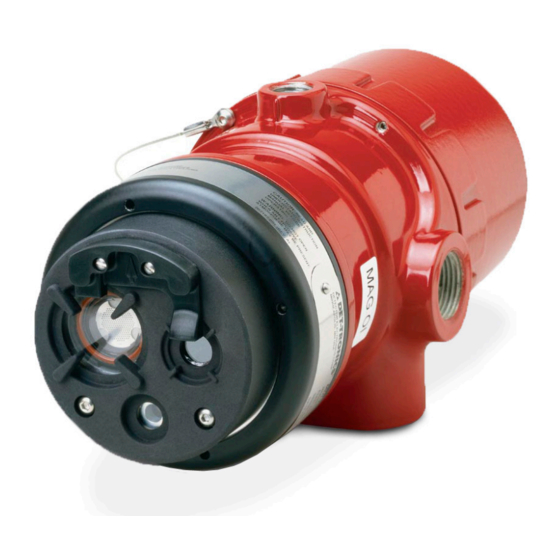
- Page 1 Instructions UVIR Flame Detector X5202 95-8788...
-
Page 2: Table Of Contents
INSTALLATION......7 X5202 Series Model Matrix ....21 Detector Positioning . -
Page 3: Description
Testing with an external test lamp is not approved or required. DESCRIPTION A tri-color LED on the detector faceplate indicates The X5202 UVIR Flame Detector provides reliable normal condition and notifies personnel of fire alarm or detection of fires that are comprised of hydrogen, fault conditions. -
Page 4: Led
LON/SLC Output The EQP model is designed for use exclusively with the Det-Tronics Eagle Quantum Premier system. The detector communicates with the system controller over a digital communication network or LON/SLC (Local Operating Network / Signaling Line Circuit). The LON/ SLC is a fault tolerant, two wire digital communication network arranged in a loop configuration. -
Page 5: Communication
IR DETECTOR OPTIONS is released, regardless of whether the detector has been configured for latching or non-latching operation. The fire The IR detector in the X5202 can be programmed for: alarm output condition stays active for three seconds on –... -
Page 6: Uv Detector Options
Gas welding mandates system inhibit, since the gas torch is an actual fire. Arc The UV detector in the X5202 can be programmed for: welding rods can contain organic binder materials in – Arc Rejection the flux that burn during the welding operation and are –... -
Page 7: False Alarm Sources
If the window cannot be high voltage corona, x-rays, and gamma radiation. eliminated or the detector location changed, contact Det-Tronics for recommendations regarding window materials that will not attenuate radiation. NOTE Radiation generated by false alarm sources such... -
Page 8: Important Safety Notes
IMPORTANT SAFETY NOTES Table 3—UV and IR Absorbing Gases and Vapors The following is a partial list of compounds that exhibit WARNING significant UV absorption characteristics. These are Do not open the detector assembly in a hazardous also usually hazardous vapors. While generally of little area when power is applied. -
Page 9: Installation
INSTALLATION • Dense fog, rain as well as certain gases and vapors (see Table 3) can absorb UV and IR radiation and reduce the sensitivity of the detector. NOTE The recommended lubricant for threads and O-rings • If possible, fire tests can be conducted to verify is a silicone-free grease (p/n 005003-001) available correct detector positioning and coverage. -
Page 10: Protection Against Moisture Damage
PROTECTION AGAINST MOISTURE DAMAGE NOTE R e f e r t o “ Po w e r C o n s u m p t i o n” i n t h e It is important to take proper precautions during “Specifications”... - Page 11 Relay and 0–20 mA Output Models To ensure that the insulating material of the wiring Follow the instructions below to install the X5202. terminal block will not be affected by the heat generated by EOL resistors, observe the following guidelines when 1.
- Page 12 DETECTOR FIRE ALARM PANEL mA + mA – SPARE SHIELD mA + REF mA – REF SPARE COM FIRE 2 COM AUX COM FIRE NO FIRE 2 NO AUX NO FIRE DEVICE 4 NC FIRE 2 NC AUX NC FIRE ALARM COM FAULT 1 RS485 A...
- Page 13 DETECTOR DETECTOR mA + mA + mA – mA – AT 24 VDC AT 24 VDC mA – REF mA + REF – – 24 VDC 24 VDC – – MAN O i MAN O i +Vin +Vin D2139 D2138 –Vin –Vin –Vin...
- Page 14 EQP Model 5. Check all field wiring to be sure that the proper connections have been made. 1. Connect external wires to the appropriate terminals inside the terminal compartment, shown in Figure 13. 6. Replace and securely tighten all covers before See Figure 14 for terminal identification.
- Page 15 CH 1 CH 2 CH 3 CH 4 CH 5 CH 6 CH 7 CH 8 RELAY 1 RELAY 2 RELAY 3 RELAY 4 DIGITAL INPUTS RELAY 5 RELAY 6 RELAY 7 RELAY 8 95-8788...
-
Page 16: Setting Device Network Addresses (Eq And Eqp Models Only)
ADDRESS SWITCHES SENSOR MODULE REMOVED FROM HOUSING A2191 Figure 16—Location of Address Switches The address number is binary encoded with each switch SETTING DEVICE NETWORK ADDRESSES having a specific binary value with switch 1 being the (EQ and EQP Models Only) LSB (Least Significant Bit), see Figure 17. -
Page 17: Startup Procedure
It is highly recommended that a complete spare 5. The use of the Enhanced Flame Inspector cable be kept on hand for field replacement to ensure and software from Det-Tronics can be considered to continuous protection. determine the nature of the fault condition. Refer to instruction manual 95-8751 for more information. -
Page 18: Maintenance
MAINTENANCE LOOSEN TWO CAPTIVE SCREWS IMPORTANT Pe r i o d i c fl a m e p a t h i n s p e c t i o n s a re n o t recommended, since the product is not intended to be serviced and provides proper ingress protection to eliminate potential deterioration of the flamepaths. -
Page 19: Periodic Checkout Procedure
Integral wiring compartment for ease of installation • Explosion-proof/flame-proof detector housing. Meets FM certification requirements. • Class A wiring per NFPA-72 • Spectral Sensitivity Range: X5202 IR wavelength range 2-3 microns, UV wavelength range 185-265 nanometers • 3 year warranty • Advanced signal processing (ARC/TDSA) -
Page 20: Specifications
SPECIFICATIONS VIEWING ANGLE 0° OPERATING VOLTAGE— 15° 15° 80 (24) 24 Vdc nominal (18 Vdc minimum, 30 Vdc maximum). 30° 30° Maximum ripple is 2 volts peak-to-peak. 70 (21) 45° 45° 60 (18) POWER CONSUMPTION— 50 (15) Without heater: 2.8 watts at 24 Vdc nominal; 4.8 watts at 24 Vdc in alarm. - Page 21 CONE OF VISION— THREAD SIZE— The detector has a 90° cone of vision (horizontal) with Conduit connection: Four entries, 3/4 inch NPT or M25. the highest sensitivity lying along the central axis. Conduit seal not required. See Figure 19. SHIPPING WEIGHT (Approximate)— Aluminum: 7 pounds (3.2 kilograms).
-
Page 22: Replacement Parts
X5202 UVIR Flame Detector section. If it is determined that the problem is caused by Refer to the X5202 Series Model Matrix below for details an electronic defect, the device must be returned to the Q9033 Mounting Arm is required: factory for repair. -
Page 23: X5202 Series Model Matrix
X5202 SERIES MODEL MATRIX MODEL DESCRIPTION X5202G UV/IR Hydrogen Flame Detector with Kr85 Free Source Tube TYPE MATERIAL Aluminum Stainless Steel TYPE THREAD TYPE 4 Port, Metric M25 4 Port, 3/4” NPT TYPE OUTPUTS Relay Relay and 0-20mA LON Eagle Quantum Premier (EQP) -
Page 24: Appendix A - Fm Approval And Performance Report
APPENDIX A FM APPROVAL AND PERFORMANCE REPORT THE FOLLOWING ITEMS, FUNCTIONS, AND OPTIONS DESCRIBE THE FM APPROVAL FOR THE X5202: • Explosion-proof for Class I, Div. 1, Groups B, C, and D (T5) Hazardous (Classified) Locations per FM 3615. •... - Page 25 FM Approval and Performance Report – Continued X5202 RESPONSE CHARACTERISTICS Very High Sensitivity UV & IR, Low Arc Rejection, TDSA or Quick Fire Fuel Size Distance feet (m) Average Response Time (seconds)* 30 inch plume / Hydrogen 75 (22.9) 100 SLPM...
- Page 26 FM Approval and Performance Report – Continued X5202 RESPONSE CHARACTERISTICS IN THE PRESENCE OF FALSE ALARM SOURCES Very High Sensitivity UV & IR, Low Arc Rejection, TDSA or Quick Fire Distance to Distance Average Response source Fuel to fire False Alarm Source...
- Page 27 FM Approval and Performance Report – Continued X5202 FIELD OF VIEW Very High Sensitivity UV & IR, Low Arc Rejection, TDSA or Quick Fire Distance Horizontal Average Horiz. Response Vertical Average Vert. Response Fuel Size feet (m) (degrees) Time (seconds)*...
-
Page 28: Appendix B - Csa Approval
APPENDIX B CSA APPROVAL DIVISION CLASSIFICATION: Ultraviolet Infrared Hydrogen Flame Detector/Controller X5202 series, rated 18-30 Vdc, 2.8 Watts to 17.5 Watts. Relay contacts rated 5 Amps @ 30 Vdc. CLASS 4818 04 - SIGNAL APPLIANCES - Systems - For Hazardous Locations Class I, Division 1, Groups B, C, and D (T5);... -
Page 29: Appendix Catex Approval
APPENDIX C ATEX APPROVAL EC-TYPE EXAMINATION CERTIFICATE DEMKO 02 ATEX 132195X Increased Safety Model Flameproof Model II 2 G II 2 G 0539 0539 ® II 2 D ® II 2 D APPROVED APPROVED Ex db eb IIC T6...T5 Gb Ex db IIC T6...T5 Gb Ex tb IIIC T80°C Db Ex tb IIIC T80°C Db... - Page 30 The following accessories are ATEX approved for use with the X5202G Flame Detector: Part Number Description 007290-001 Q9033B Stainless Steel Mounting Arm Assembly is for aluminum and stainless steel detectors 007290-002 Q9033A Aluminum Mounting Arm Assembly is for aluminum detectors only 011385-001 Q9033 Collar Attachment 95-8788...
-
Page 31: Appendix Diecex Approval
APPENDIX D IECEx APPROVAL CERTIFICATE OF CONFORMITY IECEx ULD 06.0018X Ex db eb IIC T6...T5 Gb Ex db IIC T6...T5 Gb Ex tb IIIC T80°C Db Ex tb IIIC T80°C Db T6 (T amb = –50°C to +60°C) T6 (T amb = –55°C to +60°C) T5 (T amb = –50°C to +75°C) T5 (T amb =–55°C to +75°C) IP66/IP67. -
Page 32: Appendix E - Declaration Of Conformity
APPENDIX E DECLARATION OF CONFORMITY EU Declaration of Conformity Model X5202 Series (Ultraviolet/Infrared Flame Detector) The object of the declaration described above is in conformity with the relevant Union harmonisation legislation: ATEX Directive: 2014/34/EU EN 60079-0:2012+A11:2013 Certificate No.: DEMKO 01 ATEX 132195X... - Page 33 Specifications subject to change without notice. All trademarks are the property of their respective owners. © 2020 Detector Electronics Corporation. All rights reserved. Det-Tronics manufacturing system is certified to ISO 9001— Corporate Office Phone: +1 952.941.6665 the world’s most recognized quality management standard.
Need help?
Do you have a question about the X5202 and is the answer not in the manual?
Questions and answers