
Related Manuals for Benchmark Games Ticket Station


Summary of Contents for Benchmark Games Ticket Station
- Page 1 Fax: (561)493-2999 Customer Service: (561)253-3311 www.benchmarkgames.com 2201 4 Avenue North Lake Worth Beach. FL 33461 170MAN001 03/2020...
-
Page 2: Table Of Contents
Table of Contents Manual Revision History ..............................3 Basic Components: ................................4 Game Setup: ..................................5 Unloading/Assembly: ................................ 5 If Installing a card swipe: ..............................8 Adjusting the Barcode Sensor: ............................11 Editing Option with a Computer ............................. 13 Edit Display ................................. 16 Edit Receipt: ................................ -
Page 3: Manual Revision History
No part of this artwork, music, sound effects, images, displays, software or firmware may be reproduced in any way without the express written permission of Benchmark Games Int’l. Benchmark Games Int’l. also retains other various intellectual property rights in the game machine including pending patent rights, trade press rights and trademarks. -
Page 4: Basic Components
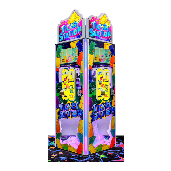
Basic Components:... -
Page 5: Game Setup
Screws. Assemble as shown in picture to the right. Once assembled place the half without legs at the top of the Ticket Station cabinet, then the set with the legs over those be sure to align them with the brackets on the inside roof. - Page 6 Once the Top Marquee is properly secured. Install the Top LED Assembly. Using the four 6-24 x 3/8 screws fasten the Top LED Assembly into place. Now you are ready to plug in the Top LEDs to the RGB light board.
- Page 7 6. Place the three layers back on the door, securing them with the six bolts removed in step 3. 7. Reconnect the seven-segment display and the VFD. 8. Once door is closed. If Ticket station is on the door will turn on.
-
Page 8: If Installing A Card Swipe
If Installing a card swipe: Locate the Ticket Station Main Controller Board on the door. 1. Speaker 2. Programming buttons 3. SD Card Holder 4. Inputs/Power(P5) 5. Output/Signals(p11) 6. RS485 Find your Card Swipe Conversion harness as shown on the right. - Page 9 Start by disconnecting the P5 and P11 connectors from your Main board. Find the corresponding Connections on the Conversion harness. There will be both a male and female end on the conversion harness. Plug the Female end into the plug that you pulled from the main board, and the Mail end of the conversion harness should plug into the main board. See example below.
- Page 10 The last two plugs left are for your Card swipe system. The small Plug being Power(A) and the larger one your signals(B). Figure A: Pin 1 – Yellow: 12V Pin 2 – Black: Ground Figure B: Pin 1 – Pink/White: Clock Pulse Pin 2 –...
-
Page 11: Adjusting The Barcode Sensor
Adjusting the Barcode Sensor: First you will need to get to the Barcode sensor. One is on the top Assembly, the other is in the lower Belt Assembly. To get to the barcode sensor on the lower assembly, follow the next few steps. - Page 12 Just remove one side from the bearing and rotate it so that it is easier to work with. Now you can rotate the adjustment pot located on the top left of the board. Rotate the pot clockwise. It starts set to 12o’clock rotate until top arm is to about 2-3 o’clock.
-
Page 13: Editing Option With A Computer
SD Card”. This will save any setting you may have already changed to the SD Card on the main control board. Once done turn off Ticket Station. Once completely powered off take out the Micro SD Card located next to the programming buttons. - Page 14 When you open the “tsconfig” file note a few things. Any entry that starts with the # symbol should not be modified/edited.
- Page 15 You can modify setting by changing the values (marked in green below) to the parameters provided after the # symbol. Example: Machine number – You can choose any number between 0 through 100. So, this is machine number 5 that section will look like this.
-
Page 16: Edit Display
Edit Display To edit the front display type in what you want it to say. This should be 20 characters (this includes spaces and symbols) or less and must be written with in the “quotation” marks. To center your phrases spaces must be added to front and back of each phrase, these spaces do count for your overall character total. -
Page 17: Edit Receipt
Edit Receipt: To edit the lines that are printed on the receipt type in what you want it to say. This should be 20 characters (this includes spaces and symbols) or less and must be written with in the “quotation” marks. To center your phrases spaces must be added to front and back of each phrase, these spaces do count for your overall character total. - Page 18 Once you have changed all settings you wish to change save the file. (CAUTION! DO NOT CHANGE THE FILE NAME!) If you have multiple machines you can save this same file to each of the micro SD cards for faster editing. Re insert the micro SD card(s) to all doors/machines, then turn on the machine.
-
Page 19: Add Logo
Add Logo: To add your very own logo there are a few requirements the logo must meet. Requirements Size – 128 x 128 – 320 x 320 (Pixels) Name – Logo File Type - .bmp The logo we are using for this demonstration is 128 x 128. Its name is “logo”... - Page 20 When done your receipt should look like the image below. The logo will always appear at the top of the printed receipt. Company Logo Company Name Welcome Message Tickets Earned Footer Message Machine Number Barcode Locate power cord shipped in bag. Connect cord to power input on the game. Plug cord into the wall. Toggle power switch to power game on.
-
Page 21: Game Play Sequence/Behavior
Game Play Sequence/Behavior Power-Up Initialization Sequence a. Various LED’s light up and flash. b. Display screen and monitors will power on. c. Sounds will play, and you can start inserting tickets or programming in your preferred option. Attraction Mode: a. Various lights and sounds are triggered at a programmable frequency. b. -
Page 22: Entering Programing Mode
(left, center, right respectively). These are used to enter the setting options for each redemption door. To enter programing mode, locate the Ticket Station Control Board on each door. Press the center button and hold for 2 seconds. The machine will audibly announce “Entering Program Mode”. -
Page 23: Programing Options
Programing Options: Total Tickets Clear Tickets Yes / No History Log Last 25 Receipts Range 0-100 Volume Default: 80 Date:MM/DD/YYYY - Date and Time Done Time: HH:MM Range 0 to 99 Machine Number Default: 0 Insert Barcode Numbers Default: 5151 Ticket Length(mm) Types A-J Ticket Types... - Page 24 Total Tickets: Displays the grand total number of tickets redeemed. Enter button: Back Next button: Clear total to zero. User asked for confirmation. History Log: Displays and allows printing of last 25 transactions, including date, time, receipt serial, and points claimed. Scroll to the sides to go through options and history entries.
- Page 25 There are 10 ticket-type fields that can be used, labeled A through J. Default: Ticket type A is the default ticket and corresponds to Benchmark Games' proprietary ticket. The user can scroll between these types by using the Back and Next` buttons. And the type name will appear on the right.
- Page 26 Ticket Speed: This option sets the ticket eater motor speed Range: 1-3 Default: 3 Fastest, about 8 tickets per second. Back button: Reduce Enter button: Return to Main menu Next button: Increment Ticket Value: This option sets the prize points value of each ticket. Range: 1/16 prize point to 8 prize points Default: 1 Back button: Reduce ticket value...
- Page 27 TS can use both original opticon and BG barcode sensors. Bar active high is for Opticon Bar active low is for BG sensor Default: Active High Back button: Toggle setting Enter button: Return to Main menu Next button: Toggle setting Language: (V1.1 07-19) Choose between English and Russian for LCD messages and paper printouts Default: English...
- Page 28 Loads custom receipt logo image from SD card into printer. Image characteristics: File name: logo.bmp. The ticket station will look for this name on the SD card at the root level. File Format: .bmp. This image format can be created with your favorite graphics editing program.
- Page 29 Receipt Check Digit: This option turns the check digit added to the receipt barcode on or off Default: On Back button: Toggle setting Enter button: Return to Main menu Next button: Toggle setting Receipt Include T2P Barcode: This option includes a secondary barcode that is compatible with the Tickets 2 Prizes redemption scheme. Default: Off Back button: Toggle setting Enter button: Return to Main menu...
- Page 30 Save to SD CardSAVE TO SD CARD Save operator options to user editable config text file When saving, the config text file is fully overwritten. Back button: No, cancel Enter button: - Next button: Yes, save Exit: Enter button: Leave Programming Mode menu. Back to normal operation.
-
Page 31: Technical Operation
Technical Operation: Standard Door Configuration: The Standard Door takes in tickets. The top display will prompt the user to “Please Insert Tickets” to begin. Once a ticket is inserted it passes through the first set of receiver and transmitter optic sensors, these sensors trigger the motor to engage and start the processes. -
Page 32: Main Electronic Components
Main Electronic Components Circuit Board Location Internal Roof Media Player Audio/Video Splitter Power Distribution RGB Light Board Power Supply Card swipe Door Standard Door Printer Card Swipe hole Stepper Motor 5 Digit Display VFD Display Ticket Cutter Assy Speaker Main Board... - Page 33 Ticket Station Control Board Part Number: 170PCB001 Location: On each individual door. ID Switch Setting: N/A This board is the main controller of the machine. It decides all the machines actions and commands the other boards to act according to the machines scheme.
- Page 34 Ticket Barcode Reader Part Number: 087PCB004/087PCB005 Location: On each ticket cutter unit. ID Switch Setting: N/A This board reads the barcode on the tickets as they are fed into the machine. Opto Receiver Part Number: PCB00046 Location: On each ticket cutter unit. ID Switch Setting: N/A These receiver boards look for the opposite transmitter and send a signal to turn on the motor and count the notches on the tickets as they enter the machine.
- Page 35 5 Digit Display Board Part Number: PCB00008 Location: On each individual door. ID Switch Setting: N/A This board is used to show the count of tickets as they are fed into the machine. Power Distribution Board Part Number: PCB00032 Location: On the inside roof of the cabinet. ID Switch Setting: N/A This board sends power to the main board, light board, display board, motors, and lights on each door and...
- Page 36 Media Player Board Part Number: ELM00405 Location: On the inside roof of the cabinet. ID Switch Setting: N/A This board is for the large tv display. HDMI Audio/Video Splitter Board Part Number: 500PCB200 Location: On the inside roof of the cabinet. ID Switch Setting: N/A This board is for the large tv display.
- Page 37 Lock Out Switch Part Number: ELM00021 Location: On each individual door frame. ID Switch Setting: N/A This switch cuts power to the door to make servicing safe. Stepper Motor Assembly Part Number: 087ASM045 Location: On each individual door. ID Switch Setting: N/A This motor engages when tickets are inserted and runs until all tickets have passed.
-
Page 38: Error Code And Troubleshooting Guide
Error Code and Troubleshooting Guide: Motor Jamming/ Restarting: If the Ticket station is counting tickets and suddenly your motors restarts, or stops altogether, check the following. First, we will look at the Ticket Taker Motor and Belt. We want to make sure that this is nice and tight. As having a loose belt could cause some skipping and throw your step count off. - Page 39 Once belt is nice and tight, we will need to look at the 4 black pulleys. We need to make sure that they are all in the correct location and are also nice and tight. There is one 27 tooth gear and three 29 tooth gears. They must be in the locations specified in the image to the right.
- Page 40 Now that our pulleys have been tightened up, we will look at our gears. We need to make sure that we have them aligned and cleaned properly. From top to bottom we have: 1. Top Cutter Gear 2. Bottom Cutter Gear 3.
-
Page 41: Ticket Jam
Finally, we will need to check the Ticket Taker Belt Assembly. Be sure that the plastic gear is not loose by tightening the sprit collar below it. Also check for any wear on the clear antistatic belts. Any of these can be a factor in the motor restarting or a ticket miscount. Be sure to check all before restarting the machine. -
Page 42: Pin Out Sheets
Pin Out Sheets: 170HNS001: Door Harness... - Page 43 Connector/ Device/ Signal Type/ Comments Color From From From From From From From From C1: Door to Main HNS Mini F connector Pin 1 Printer GND Black C6:P2 Pin 2 Main Controller Black C2:P8 Pin 3 Ground Black C19:P1 C18:P1 C16:P1 C17:P1 C11:P1...
- Page 44 Pin 10 Switch Receipt Purple/Wh C12:P1 Buton Pin 11 Opto Ticket Notch Purple/Blk C18:P2 Ticket Count Pin 12 Opto Ticket Insert Blue/Blk C19:P2 signal needed to turn (motor) on motor Pin 13 Ticket Scanner 4 Green/Org C15:P2 Pin 14 Pin 15 Ticket Scanner 3 Green/Red C15:P3 Pin 16...
- Page 45 Pin 1 RS 485 A Blue C1:P4 C4:P2 C7:P1 Is a twisted Pair with Pin 2 Pin 2 RS 485 B Gray C1:P9 C4:P1 C7:P2 Is a twisted Pair with Pin 1 Pin 3 Ground Black C1:P3 C19:P1 C18:P1 C16:P1 C17:P1 C11:P1 C7:P3...
- Page 46 C13: Hall Effect Sensor Micro F Pin 1 Power 5V C2:P7 Pin 2 Signal Blue/Gry C2:P5 Pin 3 Ground Black C2:P6 C15:P4 C14:P4 C14: Ticket Scanner 1/2 Micro F Pin 1 12V Power Yellow C1:P8 C19:P3 C18:P3 C15:P1 C16:P3 C17:P3 C9:P1 C5:P4 C7:P4...
- Page 47 Pin 1 Speaker (+) White/Blu/ C22:P1 C21: Speaker Pin 1 Speaker (-) White/Grn C22:P2 /Blu C22: Main Controller Mini F Board (P3) Pin 1 Speaker (+) White/Blu/ C20:P1 Is a twisted Pair with Pin 2 Pin 2 Speaker (-) White/Grn C21:P1 Is a twisted Pair with /Blu...
- Page 48 P a g e...
Need help?
Do you have a question about the Ticket Station and is the answer not in the manual?
Questions and answers