
Related Manuals for Benchmark Games Red Hot X-Treme 7s


Summary of Contents for Benchmark Games Red Hot X-Treme 7s
- Page 2 Table of contents Game Play Game Set-up Technical Description Programming Error Codes Electronic Components Game Specifications Parts...
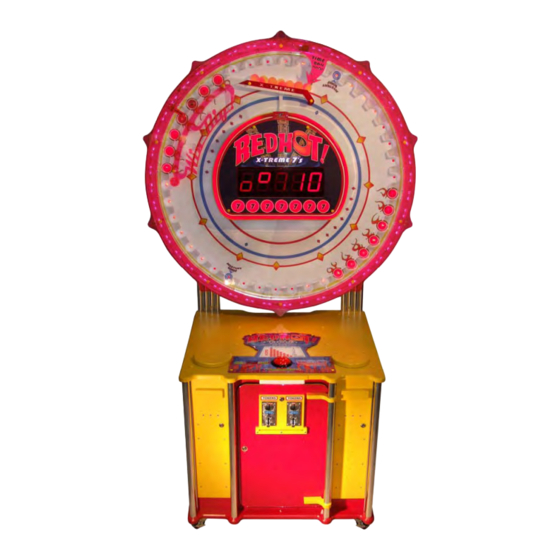
- Page 3 Red Hot X-Treme 7s Game Play The object of Red Hot X-Treme 7s is to time the ball drop button press so that the 7 balls fall into the Red Hot slots on the wheel. Fill all 7 slots wins the jackpot. Filling less than 7 Red Hot slots pays out from 9-100 tickets depending on the number of slots filled.
- Page 4 Game Assembly Red Hot base Red hot Wheel Assembly Support Pipes 1. Cut the plastic and remove the support pipes boxes 2. Remove pipes from boxes...
- Page 5 3. Remove the Red Hot Wheel from box (Wheel is very heavy) 4. Lay Red Hot Wheel on back off the ground (Wheel is very heavy) Wheel Supports 5. Remove Red Hot Wheel shipping supports, saving bolts, as they will be used later to attach the wheel to the base.
- Page 6 6. Remove Red Hot base from box 7. Slide wheel support pipes into Red Hot base...
- Page 7 8. Place a piece of foam from the shipping box onto the Red Hot Base. 9. With two people, lift the Red Hot Wheel and place on foam against the support pipes. Hold it there. 10. Now attach the wheel to the support pipes with the bolts from the shipping supports, starting with the top.
- Page 8 11. Cut the plastic wrap holding the light strips so that they hang. 12. Attach the trim pieces using the hardware provided. There are 3 screws for each pieces of trim.
- Page 9 13. Slide the light strips along the wheel and snap the tabs into the holes in the trim 14. Connect the Red Hot Wheel wires to the connecters on the Red Hot Base. 15. Connect to power source 16. Load ticket dispensers...
- Page 10 Technical Operation Wheel Position Wheel position in Red Hot X-Treme 7s is determined by Stepper Controller an optical sensor that communicates with the CPU board. Board The CPU receives a HOME signal from an optical sensor located behind the wheel. There is a pin inserted into the...
- Page 11 Programming the Red Hot X-Treme 7’s Game 1.) Entering Programming Mode To enter program mode, press and hold the right button located on the Power Distribution Board. After 2 seconds, “TOTALS” will appear on the LCD Display. At this time, release the button. “COINS IN” with the number of coins received will be displayed.
- Page 12 7.) “CHANGE PASSCODE?” Depressing Button 1 will allow for changing the passcode. Depressing Button 2 will move to “DISPLAY CONTRAST”. IMPORTANT!!! ONCE THE PASSCODE IS CHANGED, THE DEFAULT OF 0000 WILL NO LONGER WORK! BE SURE TO SAVE THE PASSCODE IN A SAFE PLACE! Entering the new passcode is accomplished in the same way that entering the passcode is done, as explained in 6.) .
- Page 13 12.) ATTRACTION FREQUENCY This option sets the frequency at which the attraction mode occurs. The settings are from OFF to every 30 minutes. Depressing Button 1 will change the settings in 1- minute increments from OFF to 30 minutes, then back to OFF. Depressing Button 2 displays the next option, “COINS PER CREDIT”.
- Page 14 total. Depressing Button 2 after all of the totals have been displayed will display the next option, “ENTER PROGRAM MODE?” 22.) “ENTER PROGRAM MODE?” This option gives the opportunity to re-enter program mode if it is necessary to change any options again. Depressing Button 2 leaves Program Mode and the game returns to normal, Run Mode.
- Page 15 Electronic Components Electronics Assembly Hi Current Driver Stepper Controller Audio Board CPU Board Power Distribution board Power Supply Power Supply (lights) Power Distribution Board LED Indicators LEDs should be ON when game is powered up. They identify which voltages LEDs should normally be are present OFF.
- Page 16 Electronic Components 485 Serial Connector CPU LED Chart CPU LED Flashes = OK 5V LED ON = 5v Stepper LED Chart 24V LED ON = 24v Stepper Controller Board CPU LED Flashes = OK ON = 5v HOME ON but dim Switch Settings All Switches OFF RS 485 Termination...
- Page 17 Electronic Components High Current Driver PCB J2 Inputs J1 Outputs Power LED LEDs turn ON only when the output is active Game Specifications Key numbers Weight Dimensions-set-up H- 94.5” W- 59.5” D- 37.5” Power consumption Fuses 2-5 amp in power supply F5L 250 volt FB Ticket dispensers 2 Benchmark Intelli triple...
- Page 18 Parts High Current PCB Stepper controller board Main CPU Power Distribution PCB 2 Digit Credit Display Jackpot 5 Digit Display Bottom bracket Top bracket Coin Chute and Mechs Control Panel Ball Assembly Optical Receivers Solenoid Assembly Wheel Support Pipes...
Need help?
Do you have a question about the Red Hot X-Treme 7s and is the answer not in the manual?
Questions and answers