
Subscribe to Our Youtube Channel
Related Manuals for YOKOGAWA Sushi Sensor XS530


Summary of Contents for YOKOGAWA Sushi Sensor XS530
- Page 1 User’s Manual XS530 Pressure Measurement Module IM 01W06F01-01EN IM 01W06F01-01EN 1st Edition...
-
Page 2: Table Of Contents
8. General Specifications ................8-1 8.1 Standard Specifications ..................8-1 8.2 MODEL AND SUFFIX CODES ................8-3 8.3 OPTIONAL ACCESSORIES ................8-3 8.4 Outline ........................8-4 8.5 Regulatory Compliance Statements ..............8-7 Revision Information ..................i 1st Edition: July 2020 All Rights Reserved, Copyright © 2020, Yokogawa Electric Corporation... -
Page 3: Introduction
<Introduction> 1. Introduction Thank you for purchasing XS530 Pressure Measurement Module. To make full use of all the functions of this product, and to use it efficiently and correctly, please read this manual thoroughly before use, understand the functions and operation sufficiently, and familiarize yourself with the operation. This manual describes the XS530 Pressure Measurement Module (Hereinafter simply referred to as XS530). The XS530 works by utilizing XS110A Wireless Communication Module (Hereinafter simply referred to as XS110A). The XS530 is powered by the battery built-in the XS110A. - Page 4 Regarding This Manual • This manual should be provided to the end user. • This manual and the identification tag attached on the packing box are essential parts of the product; keep them in a safe place for future reference. • The contents of this manual are subject to change without prior notice. • All rights reserved. No part of this manual may be reproduced in any form without Yokogawa’s written permission. • Yokogawa makes no warranty of any kind with regard to this manual, including, but not limited to, implied warranty of merchantability and fitness for a particular purpose. • If any question arises or errors are found, or if any information is missing from this manual, please inform the nearest Yokogawa sales office. • The specifications covered by this manual are limited to those for the standard type under the specified model number break-down and do not cover custom-made instruments. When products whose suffix code or...
- Page 5 NOTE Draws attention to information essential for understanding the operation and features. : Functional grounding terminal n Trademarks • Sushi Sensor is a registered trademark of Yokogawa Electric Corporation. • The registered trademarks or trademarks of the respective companies in the text do not bear the mark of TM or ®. IM 01W06F01-01EN...
-
Page 6: Safe Use Of The Product
If these instructions are not heeded, the protection provided by this instrument may be impaired. In this case, Yokogawa cannot guarantee that the instrument can be safely operated. Please pay special attention to the following points:... - Page 7 (d) Maintenance WARNING • Please do not carry out except being written to maintenance descriptions. When these procedures are needed, please contact nearest YOKOGAWA office. • Care should be taken to prevent the buildup of drift, dust or other material on the name plate. In case of its maintenance, soft and dry cloth is used. (e) Modification WARNING • Yokogawa will not be liable for malfunctions or damage resulting from any modification made to this instrument by the customer. IM 01W06F01-01EN...
- Page 8 <Introduction> (f) Explosion Protected Type Instrument WARNING • Users of explosion proof instruments should refer first to section 2.7 (Explosion Protected Instrument) of this manual. • The use of this instrument is restricted to those who have received appropriate training in the device. IM 01W06F01-01EN...
-
Page 9: Warranty
Problems occurring during the warranty period shall basically be repaired free of change. • If any problems are experienced with this product, the customer should contact the Yokogawa representative from which this product was purchased or the nearest Yokogawa office. • If a problem arises with this product, please inform us of the nature of the problem and the circumstances under which it developed, including the model specification and serial number. Any diagrams, data and other... -
Page 10: Notes On Handling
<Notes on Handling> 2. Notes on Handling The XS530 is fully factory-tested before shipment. When the XS530 is delivered, check the appearance for damage and that all the components mentioned below are included. If the XS530 is ordered without the mounting bracket, the XS530 mounting parts will not be included. -
Page 11: Transportation
<Notes on Handling> Transportation To prevent damage while in transit, leave the XS530 in the original shipping container until it reaches the installation site. Storage When an extended storage period is expected, observe the following precautions. (1) Choose a storage location that satisfies the following requirements. • A location that is not exposed to rain or water. • A location subject to a minimum of vibration or impact. -
Page 12: Pressure Connection
<Notes on Handling> n Wireless Communication Install where are no obstacles for radio waves such as walls or pipes around the product as possible. n Ambient Temperature Avoid locations subject to wide temperature variations or a significant temperature gradient. If the location is exposed to radiant heat from plant equipment, provide adequate thermal insulation and/or ventilation. -
Page 13: Restrictions On Use Of Radio Transceivers
<Notes on Handling> Restrictions on Use of Radio Transceivers IMPORTANT Although this product has been designed to prevent high frequency noise, the effect of high frequency noise may occur if the transceiver is used near the product and its wiring. Therefore, when using the transceiver, investigate the effect of the transceiver beforehand, and use the transceiver at a distance where the problem does not occur. Explosion Protected Instrument 2.7.1 ATEX Intrinsic Safety Technical data: • Certificate number: DEKRA 20ATEX0024 X • Applicable standards: EN IEC 60079-0:2018, EN 60079-11:2012... - Page 14 Pressure measurement module F02.ai Note: 1. If earthing of the Case (metallic part of the enclosure) is not ensured by installation, apply conductive connection between the Case and the earth point (or the equipotential bonding system). Installation: The equipment must be installed in accordance with EN 60079-14, local requirements, and the control drawing. Maintenance and repair: WARNING Only personnel authorized by Yokogawa Electric Corporation can repair the equipment. IM 01W06F01-01EN...
- Page 15 <Notes on Handling> 2.7.2 IECEx Intrinsic Safety Technical data: • Certificate number: IECEx DEK 19.0027X • Applicable standards: I EC 60079-0 Ed. 7.0 (2017), IEC 60079-11 Ed. 6.0 (2011) • Ex marking: Ex ib IIC T4 Gb • Ambient temperature: −40 to 60°C (–40 to 140°F) • Process temperature: −40 to 100°C (–40 to 212°F) • Electrical parameters: Connector Ui = 6.88 V, Ii = 1.54 A, Pi = 0.3 W, Ci = 3.9 μF, Li = 0 μH • Enclosure: IP66/IP67 in accordance with only IEC 60529 when combined with XS110A. Certification information: WARNING A modification of the equipment would no longer comply with the construction described in the certificate documentation. Control drawing: Hazardous Location Connector Uo ≤ Ui Ui: 6.88 V Io ≤...
- Page 16 <Notes on Handling> Installation: The equipment must be installed in accordance with IEC 60079-14, local requirements, and the control drawing. Maintenance and repair: WARNING Only personnel authorized by Yokogawa Electric Corporation can repair the equipment. IM 01W06F01-01EN...
-
Page 17: Component Names
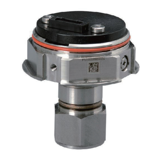
<Component Names> 3. Component Names XS110A connector XS110A fixed screw Tag plate mounting hole Hexagon nut Pressure-detector section F04.ai IM 01W06F01-01EN... -
Page 18: Installation
<Installation> 4. Installation Precautions Before installing XS530, read the cautionary notes in subsection 2.4 “Selecting the Installation Location”. For additional information on the ambient conditions allowed at the installation location, refer to chapter 8 “General Specifications”. IMPORTANT Connector Protection To protect the connector, use a protective cap (Part Number: F9097ND) when replacing batteries or installing without XS110A. The protective cap is used to temporarily protect the XS530 connector when the XS110A is removed from the XS530 during battery replacement and other operations. -
Page 19: Mounting
<Installation> Mounting IMPORTANT Be careful not to damage the receiving diaphragm. The XS530 has a dustproof plastic cap at the pipe connector. Remove the cap before piping. Take care not to damage the screw when removing the cap. Do not remove the driver by pushing it in. The product can be directly mounted to piping or mounted using a mounting bracket. - Page 20 <Installation> 4.2.1 Mounting with XS110A This section describes the installation procedures of XS110A to the XS530. Before installation, check that the battery is built-in the XS110A. F05.ai Figure 4-1 Mounting with XS110A Refer to Section 4.1 "Notes on installation" before mounting with XS110A. Align and insert the XS110A and XS530 connectors. ...
- Page 21 <Installation> 4.2.2 Installation to piping IMPORTANT Tighten the hexagon nut part of XS530. See Figure 4-2. F06.ai Figure 4-2 Tightening XS530 IM 01W06F01-01EN...
- Page 22 <Installation> 4.2.3 Mounting using bracket This section describes the installation procedure using the bracket provided with the product. U-bolt U-bolt nut 2-inch Pipe Mounting Bracket XS530 mounting bolt F07.ai Figure 4-3 XS530 Mounting n Mounting procedure for vertical 2-inch pipe Mount the XS530 to the mounting bracket using the XS530 mounting bolts with a torque of 1.4 N·m.
- Page 23 <Installation> horizontal pipe mounting screw U-bolt U-bolt Nut 2-inch Pipe Mounting Bracket F08.ai Figure 4-4 XS530 Mounting n Mounting procedure for horizontal 2-inch pipe Mount the XS530 to the mounting bracket using the XS530 mounting bolts with a torque of 1.4 N·m. Mount the Bracket to the 2-inch pipe using the U-bolt. Use the horizontal pipe mounting screws to secure the mounting bracket with a torque of 1.4 N·m. IM 01W06F01-01EN...
- Page 24 <Installation> 4.2.4 Mounting using bracket (Using a belt) This product can be attached to pipes using a belt. The belt is not included with the product, so please prepare it in advance. The belt hole that passes through the mounting bracket is 15 mm length and 3 mm wide. Use a metal belt such as stainless steel.
-
Page 25: Grounding
<Installation> Grounding Ensure continuity (Resistance less than 0.2 MΩ) between the grounding terminal and grounding pole in Figure 4-6 or Figure 4-7. Grounding resistance 100 Ω or less is recommended. If continuity between the ground terminal and the ground electrode cannot be ensured, use the following cables. Do not share the ground wiring of the XS530 with other devices. n Applicable Cables Insulated cables for industrial equipment such as;... -
Page 26: Installing Impulse Piping
<Installing Impulse Piping> 5. Installing Impulse Piping Impulse Piping Installation Precautions The impulse piping that connects the process outputs to the XS530 must convey the process pressure accurately. If, for example, gas collects in a liquid filled impulse line, or the drain for a gas-filled impulse line becomes plugged, it will not convey the pressure accurately. Since this will cause errors in the measurement output, select the proper piping method for the process fluid (gas, liquid, or steam). Pay careful attention to the following points when routing the impulse piping and connecting the impulse piping to XS530. - Page 27 <Installing Impulse Piping> (2) Position of Process Pressure Taps and XS530 If condensate (or gas) accumulates in the impulse piping, it should be removed periodically by opening the drain (or vent) plugs. However, this will generate a transient disturbance in the pressure measurement, and therefore it is necessary to position the taps and route the impulse piping so that any extraneous liquid or gas generated in the leadlines returns naturally to the process piping.
-
Page 28: Impulse Piping Connection Examples
<Installing Impulse Piping> Impulse Piping Connection Examples Figure 5.3 shows examples of typical impulse piping connections. Before connecting the XS530 to the process, study the XS530 installation location, the process piping layout, and the characteristics of the process fluid (corrosiveness, toxicity, flammability, etc.), in order to make appropriate changes and additions to the connection configurations. Note the following points when referring to these piping examples. • If the impulse line is long, bracing or supports should be provided to prevent vibration. • The impulse piping material used must be compatible with the process pressure, temperature, and other conditions. • A variety of process pressure tap valves (main valves) are available according to the type of connection (flanged, screwed, welded), construction (globe, gate, or ball valve), temperature and pressure. -
Page 29: Operation
<Operation> 6. Operation Preparation for Starting Operation NOTE • Mount the XS110A before using the product. Refer to 4.2.1 "Mounting with XS110A" for mounting method of XS110A. • Check that the process pressure take-out valve (main valve), the drain valve and the stop valve of the hand valve are closed. (1) Confirmation of installation This product is correct according to the contents of Chapter 4 "mounting" and Chapter 5 "piping of the conducting pipe". -
Page 30: Zero Point Adjustment
<Operation> Zero Point Adjustment IMPORTANT Do not remove the XS110A and XS530 after performing a zero-point adjustment. Powering off within 30 seconds of performing this procedure will return the zero point to its previous setting. When preparation for starting operation is completed, zero-point adjustment is performed. For how to adjust the zero point, refer to “IM01W06C01-01EN”. When zero-point adjustment is completed, the motor is already in operation. Start of operation Confirm that installation, wiring, network settings and operation of the product are correct before starting operation. Shutting down To stop operation, remove XS110A or set XS530 to OFF mode. NOTE • To stop operation for an extended period, remove XS530 from the process line. • Refer to “IM01W06D01-01EN” for how to remove the battery. • When storing the XS110A with the battery installed, it is recommended to set this product to OFF mode to prevent battery exhaustion. -
Page 31: Maintenance
<Maintenance> 7. Maintenance Overview WARNING Since the accumulated process fluid may be toxic or otherwise harmful, take appropriate care to avoid contact with the body or inhalation of vapors when draining condensate or venting gas from the XS530 pressure- detector section and even after dismounting the instrument from the process line for maintenance. This chapter describes the procedures required for maintenance of the product. -
Page 32: Replacing The Xs530
<Maintenance> Replacing the XS530 When replacing the XS530, follow the procedure below. Import the XS530 setting using Sushi Sensor App. Remove the installed XS530 (Refer to Chapter 4). Remove the XS110A from the XS530 being replaced and install it on the new XS530 (4 Chapter). -
Page 33: General Specifications
<General Specifications> 8. General Specifications Refer to GS 01W06F01-01EN for the latest information. Standard n PERFORMANCE SPECIFICATIONS Specifications Measurement Accuracy: n Measurement Range Pressure*: ± 0.25% of Full scale Pressure: Temperature: ± 5°C typ. Measurement Maximum *: Measurement Accuracy will be changed Range Pressure when electromagnetic noise applied. - Page 34 <General Specifications> n FUNCTIONAL Vibration Resistance: SPECIFICATION 0.21 mmP-P (10 to 60 Hz), 3 G (60 to 2 kHz) Fluid to be Measured: Shock Resistance: Gas, Liquid 50 G 11 ms Zero-point Adjustment: Conducted by Sushi Sensor App. n PHYSICAL Diagnostic Function: SPECIFICATIONS Memory failure, sensor failure, Process Connection: sensor Refer to “MODEL AND SUFFIX Measurement value error, input CODES.”...
-
Page 35: Model And Suffix Codes
<General Specifications> MODEL AND SUFFIX CODES Model Suffix Codes Description XS530 Pressure Measurement Module Inter-module Digital communication for XS-series communication Europe EU868 Area North America US915 Southeast Asia AS923 General purpose* Type ATEX intrinsic safety* IECEx intrinsic safety* Range –0.1 to 5 MPa Housing material Stainless Steel 1/2 NPT female Process connection 1/2 NPT male... -
Page 36: Outline
<General Specifications> Outline l 2-inch Horizontal Pipe Mounting Unit: mm (approx. inch) 103 (4.06) ø68 (2.68) 35 (1.38) XS110A Wireless Communication Module XS110A fixed screw Mounting bracket 2-inch Pipe (1.1) (1.77) (0.87) F16.ai (1.34) (2.72) IM 01W06F01-01EN... - Page 37 <General Specifications> l 2-inch Vertical Pipe Mounting 103 (4.06) ø68 (2.68) 35 (1.38) XS110A Wireless Communication Module XS110A fixed screw 34 (1.34) Mounting bracket 2-inch Pipe 52.5 (2.07) 105 (4.13) F17.ai IM 01W06F01-01EN...
- Page 38 <General Specifications> l Process Connection: 1/2 NPT female (Process Connection Code 4) F18.ai l Process Connection: 1/2 NPT male (Process Connection Code 7) F19.ai IM 01W06F01-01EN...
-
Page 39: Regulatory Compliance Statements
<General Specifications> Regulatory Compliance Statements This device satisfies the following standards. *: P lease confirm that an installation region fulfills an applicable standard. If additional regulatory information and approvals are required, contact a Yokogawa representative. CE Conformity : The Authorized Representative for this product in the EEA is: Yokogawa Europe B.V. Euroweg 2, 3825 HD Amersfoort, THE NETHERLANDS. RoHS Directive: EN50581 EMC Directive: EN61326-1 Class A Table 2, EN61326-2-3, EN55011 Class A CAUTION This instrument is a Class A product, and it is designed for use in the industrial environment. - Page 40 Pressure Equipment Directive: XS530 Pressure Measurement Module is categorized as pressure accessories of directive 2014/68/EU, which corresponds to Article 4, Paragraph 3 of PED, denoted as Sound Engineering Practice (SEP). The full text of the EU declaration of conformity is available at the following internet address: https://partner.yokogawa.com/global/ Canadian Safety Standards: CAN/CSA-C22.2 No.61010-1 CSA-C22.2 No.94.2 IEC 60529 Pollution degree 2 Overvoltage category I...
-
Page 41: Revision Information
Revision Information Title : XS530 Pressure Measurement Module Manual No. : IM 01W06F01-01EN Edition No. Date Page Revision Item 1st edition July 2020 New publication IM 01W06F01-01EN... - Page 42 Phone : 1-800-888-6400 Fax : 1-770-254-0928 YOKOGAWA EUROPE B. V. Euroweg 2, 3825 HD Amersfoort, THE NETHERLANDS Phone : 31-88-4641000 Fax : 31-88-4641111 YOKOGAWA ENGINEERING ASIA PTE. LTD. 5 Bedok South Road, Singapore 469270, SINGAPORE Phone : 65-6241-9933 Fax : 65-6241-9919 Printed in Japan...
Need help?
Do you have a question about the Sushi Sensor XS530 and is the answer not in the manual?
Questions and answers