
Subscribe to Our Youtube Channel
Related Manuals for YOKOGAWA PH8EHP


Summary of Contents for YOKOGAWA PH8EHP
- Page 1 User’s Manual Model PH8EHP pH Sensor for High Purity Water IM 12B7J2-01E IM 12B7J2-01E 11th Edition...
-
Page 2: Introduction
< Introduction > INTRODUCTION This manual covers the PH8EHP pH Sensor for High Purity Water. Other related items are described in the following manuals. Model Title IM No. PH8HH pH Holder for High Purity Water IM 12B07P01-01E PH8AX Accessories for pH Meter... -
Page 3: For The Safe Use Of This Equipment
YOKOGAWA can not predict in advance. Compliance with the simple apparatus requirements PH8EHP meet the simple apparatus requirements defined in the following standards. - Page 4 Any option code is available. For PH202S, model and suffix code below is available. PH202S-○-E ○ must be C or U. There are no PH202S models that meet the Korean explosion proof standards. Any option code is available. Upper limit of process temperature on the PH8EHP Transmitter used in combination FLXA21 PH202S Ambient temperature Ta 40°C 60°C...
- Page 5 < Introduction > Symbol Marks Throughout this user’s manual, you will find several different types of symbols are used to identify different sections of text. This section describes these icons. WARNING Indicates a potentially hazardous situation which, if not avoided, could result in death or serious injury. CAUTION Indicates a potentially hazardous situation which, if not avoided, may result in minor or moderate injury.
-
Page 6: After-Sales Warranty
If we replace the product with a new one, we won’t provide you with a repair report. l Yokogawa warrants the product for the period stated in the pre-purchase quotation Yokogawa shall conduct defined warranty service based on its standard. When the customer site is located outside of the service area, a fee for dispatching the maintenance engineer will be charged to the customer. - Page 7 Blank Page...
-
Page 8: Table Of Contents
<CONTENTS> Model PH8EHP pH Sensor for High Purity Water IM 12B7J2-01E 11th Edition CONTENTS INTRODUCTION .....................i For the safe use of this equipment .............ii After-sales Warranty ..................v Specification ..................... 1-1 1.1 Standard Specifications ................... 1-1 1.2 Model and Suffix codes ..................1-2 External Dimensions .................. - Page 9 Blank Page...
-
Page 10: Specification
< 1. Specification > 1. Specification The Model PH8EHP pH Sensor is used to configure a pure water pH transmission system. When this sensor is used in a PH8HH pure water holder, it is possible to measure a low conductive solution at low flow rate accurately. 1.1 Standard Specifications Measurement principle: Glass electrode method Measuring range: 0 to 14 pH Installation: Mounting in PH8HH holder... -
Page 11: Model And Suffix Codes
< 1. Specification > 1.2 Model and Suffix codes pH Sensor Model Suffix Code Option Code Description PH8EHP ..............pH sensor for high purity water Cable Length ..................10 m ..... 15 m ..... 20 m Solution Ground Tip ..... Titanium KCl Reserve Tank -TT1 ..... - Page 12 12 bags, each for preparation of 500 mL Powder for buffer solution (pH 9) K9020XC 12 bags, each for preparation of 500 mL KCl powder (for PH8EHP) K9020XU 8 bags, each for preparation of 250 mL Note: The pH value of the calibrating buffer solution may vary depending on storage conditions. Prepare a new solution from powder for accurate instrument calibration IM 12B7J2-01E 11th Edition : Nov.20,2018-00...
-
Page 13: External Dimensions
Ø38 Big volume tank KCl reserve tank Approx.75 Approx.45 (with mounting bracket) (PH8EHP-)-TT3 Approx.105 2-Ø9 (M8 screw) holes Ø105 2-inch pipe 70±0.2 (Ø60.5) Hole requirements for wall mounting F1.1.ai Figure 1.1 PH8EHP pH Sensor IM 12B7J2-01E 11th Edition : Nov.20,2018-00... -
Page 14: Installation
Preparation for Installation 2.1.1 Unpacking and Inspection The Model PH8EHP pH sensor is well packed so as to prevent damage during shipment. After removing the sensor from its shipping container, visually check the sensor for damage. NOTE (1) When delivered, the "glass electrode" and the "liquid junction" are packed separate from the sensor body. -
Page 15: Mounting Glass Electrode
< 2. Installation > 2.1.2 Mounting Glass Electrode Mount the glass electrode on the sensor body as per the following procedure: (1) Peel off the seal from the electrode mounting hole on the sensor body. (2) Remove the cap for the glass membrane. Wipe off any solution remaining on the O-ring with a tissue or other material. Remove the cap for the gold-plated pin. (4) Confirm that there is no damage on the O-ring that might affect its sealing performance. Mount the glass electrode on the sensor body. Insert the electrode in the mounting hole and screw it clockwise until the O-ring fits tightly in the hole. -
Page 16: Ph Sensor Cable Wiring Procedure
< 2. Installation > pH Sensor Cable Wiring Procedure 2.2.1 Connecting Sensor Cable Connecting Sensor Cable to Terminal Box Open the cable inlet hole in terminal box using the supplied punch tool. The location of the cable inlet hole is shown by the circle-shaped groove under the case. The end of the supplied punch tool is put in the center of this circle and it is tapped with appropriate force. -
Page 17: Installing The Sensor
(1) Mount the liquid junction in the sensor body. Peel off the seal attached to the liquid junction mounting hole in the sensor body. Screw the liquid junction gently two or three turns into the hole. The PH8EHP pH sensor comes with a KCl solution reserve tank and its mounting hardware when specified. Attach the mounting hardware to the pipe (nominal diameter 50 mm). When suffix code "-TT1" is specified, connect the KCl solution refilling tube of the sensor to the general purpose reserve tank holding a 250 mL KCl solution. With the tube connected to the sensor, remove the cap from the tank and screw the connector of the tube in securely. - Page 18 < 2. Installation > Supply a KCl solution to the sensor. For the 250-mL KCl reserve tank, mount the reserve tank on the mounting hardware with the tube connection part facing down. Using a pin supplied with the tank, make several holes in the upper part of the sides of the tank (see Figure 2.6).
- Page 19 < 2. Installation > CAUTION After supplying the KCl solution, make sure that no leakage of KCl solutions occurs. If so, grounding connections will be made at two points. This may cause unstable readings or measurement errors. Install the pH sensor to the holder. Insert the pH sensor in the liquid chamber until the liquid junction in the sensor reaches the bypass in the liquid chamber and secure the sensor with metal clamp.
-
Page 20: Maintenance On Operation
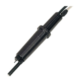
Maintenance on operation Names of Component Tip type (-H) KCl Supply Tube Pin type (-E) Glass Electrode Liquid Junction Ring type (-G) Sensor Body Reserve Tank F3.1.ai Figure 3.1 Names of Component of PH8EHP pH Sensor IM 12B7J2-01E 11th Edition : Nov.20,2018-00... -
Page 21: Operation And Periodic Maintenance
< 3. Maintenance on operation > Operation and Periodic Maintenance 3.2.1 Calibrating pH Sensor Using Buffer Solutions Calibrate pH sensor with buffer solutions before starting normal operation because the emf of glass electrodes differs somewhat from each other. The emf of a glass electrode gradually changes due to electrode staining or deterioration. Therefore, buffer solution calibration must be carried out periodically within a given period of time to keep the measurement errors within the limits specified. For more detailed information on the calibration procedures, see relevant pH transmitter/converter IMs. 3.2.2 Replenishment of KCl Solution When the KCl solution in the tank seems to be nearly exhausted while using a pH sensor with general type reserve tank, replace the reserve tank with new one (provided separately as spare part). -
Page 22: Replacing O-Rings For Glass Electrode
O-ring inside the glass electrode. For individual replacement of the O-ring, use the one recommended by Yokogawa. When installing the O-ring, wind a slip of paper or tape around the thread part on the glass electrode so as not to scratch the O-ring. - Page 23 Blank Page...
-
Page 24: Customer Maintenance Parts List
* Length of KCl Filling Tube shall be less than 60 m in case of TIIS version (Suffix code: -T, for FLXA202/FLXA21) CMPL 12B05J02-01E All Rights Reserved, Copyright © 1987, Yokogawa Electric Corporation. Subject to change without notice. 8th Edition : Jun. 2015 (YK) -
Page 26: Revision Information
Revision Information Title : Model PH8EHP pH Sensor for High Purity Water Manual No. : IM 12B7J2-01E Nov. 2018/11th Edition Added FLXA402 P i, P1-2. Aug. 2015/10th Edition Added FLXA202, Unification ot the material name P i, P1-1, P1-2. Aug. 2015/9th Edition Page ii to iii Added a postscript about Compliance with the simple apparatus requirements. - Page 27 Blank Page...
Need help?
Do you have a question about the PH8EHP and is the answer not in the manual?
Questions and answers