Table of Contents
Advertisement
Technical
Information
TI01W06A51-50EN
Contents
Introduction .............................................................................................................1
1.
Overview of the LoRaWAN Gateway ..........................................................2
2.
Preparation of Necessary Items .................................................................4
3.
Assembly and Wiring ...................................................................................5
3.1
Connecting the Ethernet Cable .......................................................................... 5
3.2
Mounting the LTE Antennas ............................................................................... 6
3.3
Inserting a SIM Card ............................................................................................ 6
3.4
Mounting the LoRa Antenna ............................................................................... 7
3.5
Mounting the GPS Antenna ................................................................................ 7
4.
Installation .....................................................................................................8
4.1
Precautions on Installation ................................................................................. 8
4.2
Mounting the Bracket on the Gateway .............................................................. 8
4.3
Installing the Gateway ......................................................................................... 9
4.4
Grounding ........................................................................................................... 10
4.5
5.
Gateway Setup ............................................................................................11
5.1
Login .................................................................................................................... 11
5.2
Basic Setting of the Gateway ............................................................................ 12
5.2.1
5.2.2
5.2.3
5.3
Data Collection Server Interface Settings ....................................................... 16
5.3.1
5.3.2
5.4
Message Transfer Settings ............................................................................... 18
6.
Operation and Maintenance ..................................................................... 22
6.1
Daily Check ......................................................................................................... 22
6.1.1
6.1.2
6.1.3
6.2
Gateway Addition and Replacement ............................................................... 23
6.2.1
6.2.2
7.
Troubleshooting ........................................................................................ 24
7.1
Checking Sushi Sensor Connection Status ................................................... 24
7.2
Changing the Radio Frequency ....................................................................... 25
7.3
Initializing the Gateway ..................................................................................... 25
7.4
Collecting Gateway Logs .................................................................................. 26
Revision Information ........................................................................................... 28
Sushi Sensor System
Setup Guide
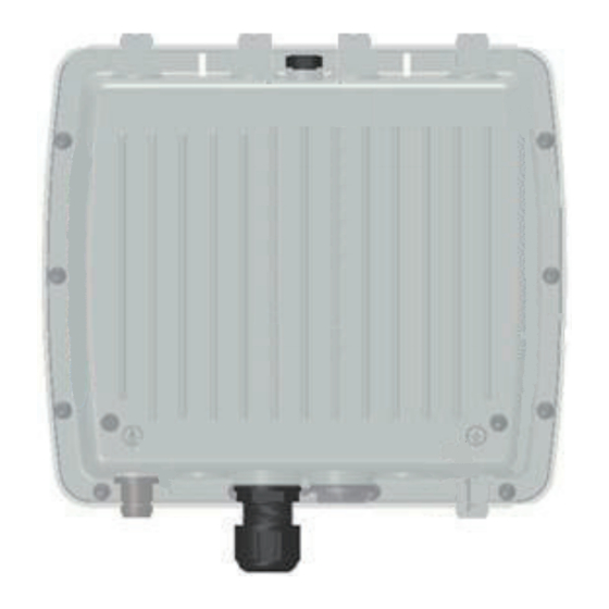
MultiConnect Conduit IP67 Base Station
Manufactured by Multi-Tech Systems
Disabling the DHCP Server ................................................................ 12
Time Settings ...................................................................................... 13
LoRaWAN Settings ............................................................................. 13
LTE Settings ........................................................................................ 16
Ethernet Settings ................................................................................ 17
Checking Wireless Communication Status ........................................ 22
Gateway Inspection ............................................................................ 22
Handling a Device in a Warning State ................................................ 22
Adding a Gateway (Providing Redundancy) ...................................... 23
Replacing a Gateway .......................................................................... 23
Yokogawa Electric Corporation
2-9-32, Nakacho, Musashino-shi, Tokyo, 180-8750 Japan
Tel.: 81-422-52-5885 Fax.: 81-422-52-2102
TI01W06A51-50EN
©Copyright Mar. 2019
1st Edition Mar. 2019
Advertisement
Table of Contents

Related Manuals for YOKOGAWA Sushi Sensor


Summary of Contents for YOKOGAWA Sushi Sensor
-
Page 1: Table Of Contents
Adding a Gateway (Providing Redundancy) ........23 6.2.2 Replacing a Gateway ................23 Troubleshooting ..................24 Checking Sushi Sensor Connection Status ........... 24 Changing the Radio Frequency ............... 25 Initializing the Gateway ..................25 Collecting Gateway Logs .................. 26 Revision Information ................... 28... -
Page 2: Introduction
Indicates that operating the hardware or software in this manner may damage it or lead to system failure. NOTE Draws attention to information essential for understanding the operation and features. TI 01W06A51-50EN Mar.26,2019-00 All Rights Reserved, Copyright © 2019, Yokogawa Electric Corporation... -
Page 3: Overview Of The Lorawan Gateway
Sensor system administrator. Set this encryption key to the gateway, and store the same key in the Support server. Android device with Sushi Sensor App installed communicate with Support server and acquire App key. Then, this encryption key is written to the Sushi Sensor through the NFC function of the Android device. Android device can also acquire encryption key via an NFC card. - Page 4 Sushi Sensor system and the application. For details, refer to the manual of the Sushi Sensor to be used and the manual of the application data collection server.
-
Page 5: Preparation Of Necessary Items
Preparation of Necessary Items When the gateway is delivered, check that the main unit and all standard accessories are included. Then, refer to “Items you need to prepare” listed below and prepare a PoE-compliant switch and an Ethernet cable. In addition, a PC equipped with an Ethernet port is required to configure various gateway settings. -
Page 6: Assembly And Wiring
Assembly and Wiring Check that the necessary items described in the preceding chapter have been prepared, and carry out assembly and wiring. Connecting the Ethernet Cable The gateway receives power from the PoE switch or injector through the Ethernet cable to carry out operations. Therefore, the Ethernet cable must be connected even if LTE communications are used as a connection to data collection server. -
Page 7: Mounting The Lte Antennas
Mounting the LTE Antennas By inserting a SIM card into the gateway, Sushi Sensor data can be directly transferred to the application on the Internet via an LTE network. Even if LTE are not used, the two LTE antennas must be mounted to protect the connectors. -
Page 8: Mounting The Lora Antenna
(3) Use a tightening torque of 2 to 3 N•m to mount the antenna. Mounting the GPS Antenna The GPS function of the gateway is not used in the Sushi Sensor system; however, the GPS antenna must be mounted to protect the connector. (1) Connect the GPS antenna to antenna connector “3” at the top of the gateway. -
Page 9: Installation
Installation This chapter describes how to install the gateway. Precautions on Installation • For information about the conditions of the installation location, refer to the gateway specifications issued by Multi-Tech Systems. • Install the gateway in an outdoor location that is as high as possible and where there are as few surrounding obstacles as possible. -
Page 10: Installing The Gateway
Installing the Gateway Attach the gateway to a pipe in the installation location. If there are no appropriate pipes, prepare one in advance. A flat blade screwdriver is required to carry out this work. Check that the following items have been prepared. • Flat blade screwdriver • Stainless hose band (x 2) • Gateway with the bracket mounted CAUTION • To mount the gateway, use a pipe with a diameter of 50 to 125 mm. -
Page 11: Grounding
Grounding Directly connect the ground terminal to class D grounding (third class grounding) with a grounding resistance of 100 Ω or less. The grounding screw is provided in the rear of the unit. For the grounding cable, use an electrical wire that has a conductor cross-sectional area of AWG14 or greater and that is based on outdoor specifications. Attach a round crimping terminal to the end of the cable. Pass the round crimping terminal through the grounding screw in the rear of the unit, and tighten it using a tightening torque of 1.69 N•m. -
Page 12: Gateway Setup
Gateway Setup This chapter describes how to set up the gateway. IMPORTANT • In the settings of this gateway, the DHCP server is enabled by default. Before configuring initial settings, ensure that this gateway is only connected to the configuration PC. NOTE • Changes made to the settings of this gateway are applied by selecting [Save and Restart]. If you have made any changes, do not forget to click [Save and Restart]. Login After logging in to the gateway via the Web browser, start the setup work. The IP address, user name, and password are required to set up the gateway. The factory default settings are as follows. • IP address: 192.168.2.1 • User name: admin • Password: admin When you log in to the gateway for the first time via the Web browser, the First Time Setup... -
Page 13: Basic Setting Of The Gateway
Basic Setting of the Gateway This section describes how to disable the DHCP server, set the gateway time, and configure LoRaWAN settings. 5.2.1 Disabling the DHCP Server The DHCP server function is enabled by default. In this section, disable the DHCP server. When using the DHCP server function of this gateway, proceed to the next section. (1) Access the gateway via the Web browser, and log in to the gateway. -
Page 14: Time Settings
5.2.2 Time Settings Set the system time of the gateway. (1) Access the gateway via the Web browser, and log in to the gateway. (2) Click [Setup] to display the sub menu. Click [Time]. (3) In [Time], type the time in 24-hour notation. As necessary, change [Time Zone] to the time zone of the region in which the gateway is to be used. (4) Click the [Submit] button. - Page 15 2 - SF10BW125 2 - SF10BW125 Max Datarate 5 - SF7BW125 6 – SF6BW125 (6) Specify the log-related items. Change [Path] of [Network Server Logging] to “/var/log/”, and [Log Level] to [MAXIMUM]. (7) Click the [Submit] button. (8) Click [Key Management] in the sub menu of the [LoRaWAN] menu, and set [Location] of [Join Server] to [Local Key]. (9) Specify App EUI and App Key. Set the [Local Network Settings] items to the parameters shown below. These settings are required in the network settings of each Sushi Sensor. For details about the Sushi Sensor settings, refer to the relevant manual. TI 01W06A51-50EN Mar.26,2019-00...
- Page 16 Item Value Enabled Checked Network ID (AppEUI) Specify the EUI-64 address of the gateway. Hexadecimal notation. Delimit each byte using a colon (:). Network Key (AppKey) Sixteen arbitrary bytes. Hexadecimal notation. Delimit each byte using a colon (:). NOTE App EUI is generated from the MAC address of the gateway. The MAC address is indicated as “NODE” on the [Device Information] page or the nameplate of the gateway.
-
Page 17: Data Collection Server Interface Settings
Data Collection Server Interface Settings To transfer sensor data of a Sushi Sensor to the application, configure interface settings for connecting the gateway to the application. To transfer data to the application, use LTE or Ethernet. 5.3.1 LTE Settings Configure LTE communication settings. If you do not use LTE communications, skip this procedure. NOTE • Configure the LTE settings with the SIM card inserted. (1) Access the gateway via the Web browser, and log in to the gateway. (2) Click [Cellular] to display the sub menu. Click [Cellular Configuration]. -
Page 18: Ethernet Settings
5.3.2 Ethernet Settings The default IP address is set to the Ethernet port of this gateway. When the IP address and/or default gateway setting must be changed to match the installation network, follow the procedure below to change the setting(s). (1) Access the gateway via the Web browser, and log in to the gateway. -
Page 19: Message Transfer Settings
Message Transfer Settings This section describes the setting required to transfer Sushi Sensor data received by the gateway to the application. To configure this setting, use the “Node-RED” software that runs on the Web browser. Node-RED, combined with functions called “nodes”, offers a visual programming environment. In this section, “nodes” are referred to as “blocks”. NOTE • In order to configure the message transfer settings, configuration information (URL, user name, and password) of the application that is the connection destination is required. Before starting the gateway setting procedure, check the application setting. (1) Access the gateway via the Web browser, and log in to the gateway. (2) Click [Apps]. - Page 20 (7) Drag and drop the “function” block from the left pane to the sheet (Sheet1) in the center. Double-click the “function” block you have placed. (8) Configure the following settings in the [Edit function node] window. After configuring the settings, click the [OK] button. Item Value Name Overwrite Payload Function msg.payload = { data: { payload: msg.payload, eui: msg.eui, ack: msg.ack, appeui: msg.appeui,...
- Page 21 Item Value Method POST Use basic Checked authentication? Username Password Name Arbitrary character string (Example: Send http POST) *1: URL, Username, and Password are information required to transfer data to the application. These values must match the values specified for application engineering. (12) Drag the connection point of the “function” block to connect it to the “http request” block with a line. (13) Drag and drop the “debug” block from the left pane to the sheet (Sheet1) in the center. Double-click the “debug”...
- Page 22 (15) Drag the connection point of the “function” block to connect it to the “debug” block with a line. (16) Click the [Deploy] button. When “Successfully deploy” is displayed, the setting is completed. TI 01W06A51-50EN Mar.26,2019-00...
-
Page 23: Operation And Maintenance
If a warning message appears due to a low battery level of a Sushi Sensor, replace the battery as soon as possible regardless of the displayed number of days. For details about the replacement procedure, refer to the Sushi Sensor user’s manual. -
Page 24: Gateway Addition And Replacement
The new gateway App EUI and App Key values must be different from those of the gateway that has already been used. The gateway configuration can be made redundant by additionally registering a new gateway in Sushi Sensors via an Android device. To register a gateway, access the network setting of each Sushi Sensor. For details, refer to the Sushi Sensor user’s manual. 6.2.2 Replacing a Gateway To replace a gateway, configure a new gateway using the same information as that which was configured for the old gateway. The new gateway App EUI and App Key settings must be the... -
Page 25: Troubleshooting
Message sending/receiving counter for the Sushi Sensor. If the target Sushi Sensor is not found in the list or the message sending/receiving counter is not incremented, it is assumed that the Sushi Sensor battery power has been empty, the network setting is not correct, the distance between the Sushi Sensor and the gateway is too long, or there is a problem with the communication environment. -
Page 26: Changing The Radio Frequency
Changing the Radio Frequency This section describes how to change the frequency the Sushi Sensor system uses. If many wireless devices using the same frequency band are provided in the gateway communication area, it may be difficult to connect the Sushi Sensor to the gateway. Such a problem may be improved by changing the frequency of the Sushi Sensor system. (1) Access the gateway via the Web browser, and log in to the gateway. (2) Click [LoRaWAN] to display the sub menu. Click [Network Setting]. (3) Change the value of [Additional Channels]. Select the appropriate setting value from the table shown below. Specify a value that is different from the frequency of the nearby wireless system if possible. Setting Value Item Japan 922.6 MHz (default) from 865.5 MHz 924.2 MHz Additional to 867.5 MHz (0.2 MHz step) -
Page 27: Collecting Gateway Logs
(3) Mount the SIM/USB cover. The tightening torque for the SIM/USB cover is 1.18 N•m. (4) When approximately 10 minutes have elapsed, the gateway starts in the factory default state. Collecting Gateway Logs This section describes how to acquire gateway logs. Logs can be collected from the gateway if necessary. However, the amount of log data that can be stored in the gateway is small, so it may not be possible to store logs that have been collected for a long period. - Page 28 Then, configure the log sending settings on the gateway. (5) Access the gateway from the Web browser, and log in to the gateway. (6) Click [Administration] to display the sub menu. Click [Debug Options]. (7) In [Remote Syslog], configure settings to send logs to the outside of the gateway. Item Value Enabled Checked IP Address IP address of the logging PC (8) Click the [Submit] button. (9) Click the [Save and Restart] button to restart the gateway. After the gateway is restarted, gateway logs are sent. Check in Visual Syslog Sever that gateway logs have been received. TI 01W06A51-50EN Mar.26,2019-00...
-
Page 29: Revision Information
Revision Information Title : LoRaWAN Gateway Setup Guide Manual number : TI 01W06A51-50EN Edition Date Revised Item March 2019 New issue TI 01W06A51-50EN Mar.26,2019-00...
Need help?
Do you have a question about the Sushi Sensor and is the answer not in the manual?
Questions and answers