
Related Manuals for GEM R563


Summary of Contents for GEM R563
- Page 1 GEMÜ R563 Motorized control valve Operating instructions further information webcode: GW-R563...
- Page 2 All rights including copyrights or industrial property rights are expressly reserved. Keep the document for future reference. © GEMÜ Gebr. Müller Apparatebau GmbH & Co. KG 17.07.2020 GEMÜ R563 2 / 53 www.gemu-group.com...
-
Page 3: Table Of Contents
LED symbols ............Definition of terms ..........Warning notes ............ 2 Safety information ............ 3 Product description ........... 4 GEMÜ CONEXO ............5 Correct use ............... 6 Order data ..............7 Technical data ............8 Dimensions ............... 13 9 Manufacturer's information ........15 Delivery ............... -
Page 4: General Information
Flashing Hot plant components! 1.4 Definition of terms Working medium Replacement of spare parts The medium that flows through the GEMÜ product. 1.5 Warning notes Wherever possible, warning notes are organised according to the following scheme: SIGNAL WORD Type and source of the danger... -
Page 5: Safety Information
13. Maintain the product correctly. 14. Do not carry out any maintenance work and repairs not described in this document without consulting the manu- facturer first. In cases of uncertainty: 15. Consult the nearest GEMÜ sales office. www.gemu-group.com 5 / 53 GEMÜ R563... -
Page 6: Gemü Conexo
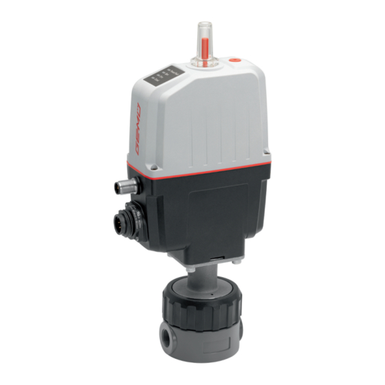
● explosive zones. 3.3 Description WARNING The GEMÜ R563 2/2-way straight seat control valve has a body with an integrated control mechanism. The GEMÜ R563 Improper use of the product valve was specially developed for controlling small quantities ▶ Risk of severe injury or death. -
Page 7: Order Data
24 V DC 8 Control module Positioner 9 Control characteristic Regulating cone, equal-percentage 10 Kv value 63 l/h 11 Actuator version Actuator size 0 12 CONEXO Integrated RFID chip for electronic identification and traceability www.gemu-group.com 7 / 53 GEMÜ R563... -
Page 8: Technical Data
Data for extended temperature ranges on request. Please note that the ambient temperature and media tem- perature generate a combined temperature at the valve body which must not exceed the above values. Leakage rate: Seat seal Standard Test procedure Leakage rate Test medium PEEK, PVC, PVDF DIN EN 60534-4 GEMÜ R563 8 / 53 www.gemu-group.com... - Page 9 4000 1600 3500 1400 3000 1200 2500 1000 2000 1500 1000 Stroke [mm] Stroke [mm] Characteristic Kv values DN 10 Kv values DN 15 1000 2500 1600 3300 1600 3300 Kv values in l/h www.gemu-group.com 9 / 53 GEMÜ R563...
- Page 10 ▶ With reduced forces, higher duty cycles and/or higher ambient temperatures are possible. At higher force settings the duty cycle and/or ambient temperature is reduced. ▶ IO-Link: Index 0x90 - Subindex 2 - Force GEMÜ R563 10 / 53 www.gemu-group.com...
- Page 11 0/4 - 20 mA; 0 - 10 V (function selectable via IO-Link) Output type: active Accuracy: ≤ ±1% of full flow Temperature drift: ≤ ±0.1% / 10°K Load resistor: ≤ 750 kΩ Resolution: 12 bit www.gemu-group.com 11 / 53 GEMÜ R563...
- Page 12 20 ms (eSyStep positioner, code S0) Vendor-ID: Device-ID: 1906801 (eSyStep positioner, code S0), Product-ID: eSyStep Positioner (code S0) ISDU support: SIO operation: IO-Link specification: V1.1 IODD files can be downloaded via https://ioddfinder.io-link.com/ or www.gemu-group.com. GEMÜ R563 12 / 53 www.gemu-group.com...
-
Page 13: Dimensions
8 Dimensions 8 Dimensions 8.1 Installation and actuator dimensions Actuator version 130.5 59.4 62.49 114.99 133.49 Dimensions in mm www.gemu-group.com 13 / 53 GEMÜ R563... - Page 14 3, 6, 10 3, 6, 10 G 3/4 DN 15 Dimensions in mm 1) Connection type Code 1: Threaded socket DIN ISO 228 2) Valve body material Code 1: PVC-U, grey / regulating cone PEEK GEMÜ R563 14 / 53 www.gemu-group.com...
-
Page 15: Manufacturer's Information
▶ Damage to the GEMÜ product. 4. Do not store solvents, chemicals, acids, fuels or similar Provide precautionary measures against exceeding the ● fluids in the same room as GEMÜ products and their maximum permitted pressures caused by pressure spare parts. surges (water hammer). -
Page 16: Installation Position
14. Please note the flow direction. 15. Please note the installation position (see chapter "Install- ation position"). 10.2 Installation position GEMÜ recommend installing the actuator vertically upright or vertically down to optimise the service life. 10.3 Installation with threaded sockets NOTICE Sealing material ▶... -
Page 17: Electrical Connection
Connection X2 (only for control module code S0) 5-pin M12 plug, A-coded Signal name I+/U+, set value input I-/U-, set value input I+/U+, actual value output I-/U-, actual value output n. c. www.gemu-group.com 17 / 53 GEMÜ R563... - Page 18 0 – 20 mA 0 – 10 V Analogue output 4 – 20 mA 4 – 20 mA 4 – 20 mA 4 – 20 mA 0 – 20 mA 0 – 10 V GEMÜ R563 18 / 53 www.gemu-group.com...
-
Page 19: Specific Data Io-Link (Pin 6)
12.1 Operation on IO-Link 12.1.1 Operation on PLC as a 24 V device The motorized actuator GEMÜ eSyStep can be operated directly in a PLC control unit without limitations. Technical data of the product and of PLC must be complied with. - Page 20 2. Connect pin 4 (CQ) of the master with pin 6 of the product. During IO-Link operation, pin 6 cannot be evaluated by the PLC control unit as an output signal. Item Name eSyStep PLC with supply voltage USB IO-Link Master USB interface Mains plug – laptop GEMÜ R563 20 / 53 www.gemu-group.com...
- Page 21 In this case, the master is connected as when the power supply is identical ● Connect pin 4 (CQ) IO-Link master with pin 6 of the product. Do not connect (pin 3) L- IO-Link master. (L-) Item Name eSyStep B1 and B2 Supply voltages USB IO-Link Master www.gemu-group.com 21 / 53 GEMÜ R563...
-
Page 22: Process Data
0 → Process valve not in Closed position 1 → Process valve in Closed position Operating mode 0 → Normal operation 1 → Initialization mode Valve position analog 8 … 23 Position of the valve in the range 0 … 1000 GEMÜ R563 22 / 53 www.gemu-group.com... -
Page 23: Parameter Overview
Product ID Read out product "eSyStep Positioner" 0x15 Serial number Read out serial "XXXXXXXX/YYYY" number 0x16 Hardware revision Read out hard- "Rev. XX/XX" ware version 0x17 Firmware revision Read out software "V X.X.X.X." version www.gemu-group.com 23 / 53 GEMÜ R563... - Page 24 1 → Active low Output 2 Configure logical 0 → Active high digital output 1 → Active low 0x4F Error action Error action Set safety position 0 → Hold 1 → Open 2 → Close GEMÜ R563 24 / 53 www.gemu-group.com...
- Page 25 Operating time 0 to 255 CLOSE (0 to 25.5s) 0x90 Drive sets Force Force, dependent 1 … 6 on valve used Force initialization Force during ini- 1 … 6 tialization, de- pendent on valve used www.gemu-group.com 25 / 53 GEMÜ R563...
- Page 26 1 → 4 to 20 mA 2 → 0 to 10 V Min. Determine min- 0 to Max imum signal out- (0.0% to Max) Determine max- 1000 Min to 1000 imum signal out- (Min to 100%) GEMÜ R563 26 / 53 www.gemu-group.com...
-
Page 27: Parameter
Type Values Rights Data storage index 0x03 1 byte Data Storage Cmd UIntegerT8 1 byte State Property UIntegerT8 4 bytes Data Storage Size UIntegerT32 4 bytes Parameter Check- UIntegerT32 Index List Octet- bytes StringT www.gemu-group.com 27 / 53 GEMÜ R563... - Page 28 Profile 0x0D 8 bytes ArrayT 0x8000 Characteristics 0x8002 0x8003 0x8100 Description of parameter values Index name Parameter Values Description Profile Characteristics 0x8000 Device identification objects 0x8002 Process data mapping 0x8003 Diagnostics 0x8100 External identification GEMÜ R563 28 / 53 www.gemu-group.com...
- Page 29 12.4.8 Product name The device name can be read out in ASCII format with the Product name parameter. Off- Access Length Index name Parameter Type Values Rights Product name 0x12 18 byte StringT "eSyStep Positioner" www.gemu-group.com 29 / 53 GEMÜ R563...
- Page 30 A text with 32 characters can be stored in the device with the Application specific tag parameter. For example, installation location, function, installation date, etc. Off- Access Length Index name Parameter Type Values Rights Application 0x18 StringT „**************** " specific tag bytes GEMÜ R563 30 / 53 www.gemu-group.com...
- Page 31 Length Index name Parameter Type Values Rights Detailed Device 0x25 39 byte ArrayT See chapter 12.5 Events Status Description of parameter values Index name Parameter Values Description Detailed Device Status See chapter 12.5 Events www.gemu-group.com 31 / 53 GEMÜ R563...
- Page 32 The functions of the digital inputs can be configured with the Function digital inputs parameter. Off- Access Lengt Index name Parameter Type Default Values Rights Function digital 0x4B 3 bits Input 1 uint:8 inputs 3 bits Input 2 uint:8 GEMÜ R563 32 / 53 www.gemu-group.com...
- Page 33 If there is no signal, the device moves into the safety position. The safety position is defined by the parameter Error Action (index 0x4F (see "Error Action'"). (Init) Input can be used as an initialization input. www.gemu-group.com 33 / 53 GEMÜ R563...
- Page 34 (Output Error & Warning) Output error and warnings. (Input Init) Configure input/output as initialization input. (Push-Pull) Configure output as Push-Pull. Type in- / output (NPN) Configure output as NPN. (PNP) Configure output as PNP. GEMÜ R563 34 / 53 www.gemu-group.com...
- Page 35 (Active high) Input 2 not inversed. Input 2 (Active low) Input 2 inversed. (Active high) Input/output not inversed. Input / output 1 (Active low) Input/output inversed. (Active high) Output not inversed. Output 2 (Active low) Output inversed. www.gemu-group.com 35 / 53 GEMÜ R563...
- Page 36 (Open) Actuator moves to the OPEN position in case of an error. (Close) Actuator moves to the CLOSED position in case of an error. Error time 1 … 1000 Determine delay time between error detection and error message. GEMÜ R563 36 / 53 www.gemu-group.com...
- Page 37 Operating mode for positioner activated. Operating mode for OPEN/CLOSE control activated. (Disabled) Use of IO-Link process data (see “Process data“, IO-Link process data page 22) is deactivated. (Enabled) Use of IO-Link process data (see “Process data“, page 22) is activated. www.gemu-group.com 37 / 53 GEMÜ R563...
- Page 38 Values Description Initialized positions Open 0 … 4092 Analog value valve position OPEN Close 0 … 4092 Analog value valve position CLOSED Stroke 0 … 4092 Analog value stroke (difference between OPEN and CLOSED). GEMÜ R563 38 / 53 www.gemu-group.com...
- Page 39 Read out current analog value of the supply voltage. Temperature 0 … 4095 Read out current analog value of the temperature sensor. Set value (W) 0 … 4095 Read out current analog value of the set value. www.gemu-group.com 39 / 53 GEMÜ R563...
- Page 40 Force initialization 1 … 6 Set the force during initialization. Preset at the factory depending on the valve type. Force settings Actuator size Setting parameter Force AG0 and AG1 Minimum force Maximum force GEMÜ R563 40 / 53 www.gemu-group.com...
- Page 41 Open / close tight Open tight 800 … 1000 Set the sealing function valve position OPEN. (80.0 … 100.0 Close tight 0 … 200 Set the sealing function valve position CLOSED. (0 … 20.0 %) www.gemu-group.com 41 / 53 GEMÜ R563...
- Page 42 Set the stroke limiter of the control range in valve position 1000 OPEN. (Min Pos to 100.0%) Min pos 0 to Max Pos Set the stroke limiter of the control range in valve position (0.0% to Max CLOSED. Pos) GEMÜ R563 42 / 53 www.gemu-group.com...
- Page 43 "Set value too high" is issued. U max 100 to 110 Determine maximum value of the voltage input. If the set (10.0 to 11.0 V) value is exceeded, the message "Set value too high" is issued. www.gemu-group.com 43 / 53 GEMÜ R563...
-
Page 44: Events
Event Description Possible cause Troubleshooting Device Hardware Fault The event occurs when a Fault in valve position Contact GEMÜ Support 0x5000 hardware fault is detected. detection. Parameter can no longer be read when switching the device on. Motor Unable To Move... - Page 45 Error when replacing a "Open" direction. diaphragm (stroke of the valve in incorrect area). Actuator has been fitted on the valve incorrectly (stroke of the valve in the incorrect area). www.gemu-group.com 45 / 53 GEMÜ R563...
-
Page 46: Operation
ð Turn anticlockwise to open the valve. 2. Valve automatically moves into the OPEN position. 3. Valve automatically moves into the CLOSED position. 4. Initialization mode is automatically ended. 5. The end positions are set. GEMÜ R563 46 / 53 www.gemu-group.com... -
Page 47: Inspection And Maintenance
14.1 Spare parts The product can only be repaired at GEMÜ. The replacement WARNING of spare parts may only be carried out by GEMÜ. If this pro- The equipment is subject to pressure! cedure is not observed, the purchaser's guarantee rights and the manufacturer's legal liability cease. -
Page 48: Troubleshooting
Emergency power operation, OPEN position Emergency power operation, CLOSED position Emergency power operation, position unknown Set value too small Set value too high Maintenance required, OPEN position Maintenance required, CLOSED position Maintenance required, position unknown GEMÜ R563 48 / 53 www.gemu-group.com... - Page 49 Valve body / actuator damaged Replace valve body/actuator Body of the GEMÜ product is leaking Body of the GEMÜ product is faulty or Check the body of the GEMÜ product for corroded potential damage, replace body if...
-
Page 50: Removal From Piping
3. Disassemble the product. Observe warning notes and goods can be processed only when this note is completed. If safety information. no return delivery note is included with the product, GEMÜ cannot process credits or repair work but will dispose of the 17 Disposal goods at the operator's expense. -
Page 51: Declaration Of Conformity According To 2014/68/Eu (Pressure Equipment Directive)
EN 1983, AD 2000 Note for products with a nominal size ≤ DN 25: The products are developed and produced according to GEMÜ process instructions and quality standards which comply with the requirements of ISO 9001 and ISO 14001. According to Article 4, Paragraph 3 of the Pressure Equipment Directive 2014/68/EU these products must not be identified by a CE-label. -
Page 52: Declaration Of Conformity According To 2014/30/Eu (Emc Directive)
20 Declaration of conformity according to 2014/30/EU (EMC Directive) EU Declaration of Conformity in accordance with 2014/30/EU (EMC Directive) GEMÜ Gebr. Müller Apparatebau GmbH & Co. KG Fritz-Müller-Straße 6-8 74653 Ingelfingen-Criesbach, Germany declare that the product listed below complies with the safety requirements of the EMC Directive 2014/30/EU. - Page 53 GEMÜ Gebr. Müller Apparatebau GmbH & Co. KG Subject to alteration Fritz-Müller-Straße 6-8, 74653 Ingelfingen-Criesbach, *88714506* Germany 07.2020 | 88714506 Phone +49 (0)7940 123-0 · info@gemue.de www.gemu-group.com...
Need help?
Do you have a question about the R563 and is the answer not in the manual?
Questions and answers