
Related Manuals for GEM R677


Summary of Contents for GEM R677
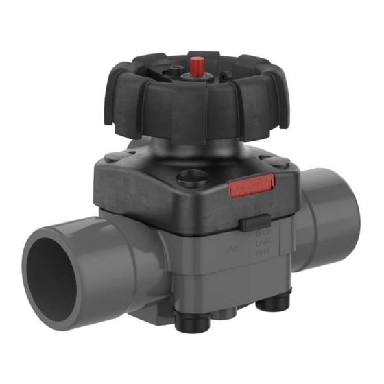
- Page 1 GEMÜ R677 Manually operated diaphragm valve Operating instructions further information webcode: GW-R677...
- Page 2 All rights including copyrights or industrial property rights are expressly reserved. Keep the document for future reference. © GEMÜ Gebr. Müller Apparatebau GmbH & Co. KG 08.07.2024 GEMÜ R677 2 / 33 www.gemu-group.com...
-
Page 3: Table Of Contents
Mounting the diaphragm ......16.4 Mounting the actuator ........16.5 Sectional drawing and spare parts ....17 Disposal .............. 18 Returns ..............19 EU Declaration of Conformity in accordance with 2014/68/EU (Pressure Equipment Directive) ..www.gemu-group.com 3 / 33 GEMÜ R677... -
Page 4: General Information
1.3 Definition of terms Corrosive chemicals! Working medium The medium that flows through the GEMÜ product. Diaphragm size Uniform seat size of GEMÜ diaphragm valves for different Hot plant components! nominal sizes. 1.4 Warning notes Maximum permissible pressure exceeded. Wherever possible, warning notes are organised according to... -
Page 5: Safety Information
The product is designed for use in piping. It controls a flowing medium by manual operation. The valve body and the dia- In cases of uncertainty: phragm are available in various designs as shown in the data- 15. Consult the nearest GEMÜ sales office. sheet. www.gemu-group.com 5 / 33... -
Page 6: Correct Use
The product is designed for installation in piping systems and for controlling a working medium. The product is not intended for use in potentially explosive areas. ● Use the product in accordance with the technical data. GEMÜ R677 6 / 33 www.gemu-group.com... -
Page 7: Order Data
FTF EN 558 series 1, ISO 5752, 10 CONEXO Code basic series 1, length only for body configuration D Without Integrated RFID chip for electronic identification and 5 Valve body material Code traceability PVC-U, grey PP, reinforced PVDF www.gemu-group.com 7 / 33 GEMÜ R677... -
Page 8: Order Example
PVC-U, grey 6 Diaphragm material EPDM 7 Control function Manually operated 8 Actuator version Actuator size EDZ 9 Special version NSF 61 water approval 10 CONEXO Integrated RFID chip for electronic identification and traceability GEMÜ R677 8 / 33 www.gemu-group.com... -
Page 9: Technical Data
10,0 10,0 10,0 10,0 10,0 10,0 Data for extended temperature ranges on request. Please note that the ambient temperature and media temper- ature generate a combined temperature at the valve body which must not exceed the above values. www.gemu-group.com 9 / 33 GEMÜ R677... -
Page 10: Product Conformity
6.4 Product conformity Pressure Equipment Dir- 2014/68/EU ective: Food: FDA* Regulation (EC) No. 1935/2004 Regulation (EC) No. 10/2011* EAC: TR CU 010/2011 Drinking water: NSF/ANSI* * depending on version and/or operating parameters GEMÜ R677 10 / 33 www.gemu-group.com... -
Page 11: Mechanical Data
0.73 0.83 0.93 1.13 2.36 0.57 0.47 1.00 1.40 1.50 1.60 3.08 0.92 3.57 3.20 4.00 3.30 6.70 4.40 4.00 8.20 MG = diaphragm size Weights in kg Installation position: Optional Flow direction: Optional www.gemu-group.com 11 / 33 GEMÜ R677... -
Page 12: Dimensions
40 - 50 114.0 99.0 101.0 140.0 119.0 122.0 214.0 167.0 169.0 214.0 216.0 211.0 Dimensions in mm * only for control function code L * CT = A + H1 (see body dimensions) GEMÜ R677 12 / 33 www.gemu-group.com... -
Page 13: Body Dimensions
Code 30: Spigot – inch, for welding or solvent cementing, depending on the body material 2) Valve body material Code 1: PVC-U, grey Code 4: ABS Code 5: PP, reinforced Code 20: PVDF Code 71: Inliner PP-H, grey, outliner PP, reinforced Code 75: Inliner PVDF/outliner PP, reinforced www.gemu-group.com 13 / 33 GEMÜ R677... - Page 14 MG = diaphragm size 1) Connection type Code 20: Spigot for IR butt welding 2) Valve body material Code 20: PVDF Code 71: Inliner PP-H, grey, outliner PP, reinforced Code 75: Inliner PVDF/outliner PP, reinforced GEMÜ R677 14 / 33 www.gemu-group.com...
- Page 15 Code 7: Union end with insert (socket) – DIN 2) Valve body material Code 1: PVC-U, grey Code 4: ABS Code 71: Inliner PP-H, grey, outliner PP, reinforced Code 75: Inliner PVDF/outliner PP, reinforced www.gemu-group.com 15 / 33 GEMÜ R677...
- Page 16 Code 33: Union end with inch insert – BS (socket) Code 3M: Union end with inch insert – ASTM (socket) Code 3T: Union end with insert – JIS (socket) 2) Valve body material Code 1: PVC-U, grey Code 4: ABS GEMÜ R677 16 / 33 www.gemu-group.com...
- Page 17 MG = diaphragm size 1) Connection type Code 78: Union end with insert (for IR butt welding) – DIN 2) Valve body material Code 71: Inliner PP-H, grey, outliner PP, reinforced Code 75: Inliner PVDF/outliner PP, reinforced www.gemu-group.com 17 / 33 GEMÜ R677...
- Page 18 MG = diaphragm size 1) Connection type Code 7R: Union end with insert (Rp threaded socket) – DIN Code 3P: Union end with insert (NPT threaded socket) 2) Valve body material Code 1: PVC-U, grey GEMÜ R677 18 / 33 www.gemu-group.com...
- Page 19 Code 4: Flange EN 1092, PN 10, form B, face-to-face dimension FTF EN 558 series 1, ISO 5752, basic series 1 2) Valve body material Code 1: PVC-U, grey Code 5: PP, reinforced Code 20: PVDF www.gemu-group.com 19 / 33 GEMÜ R677...
- Page 20 Code 4: Flange EN 1092, PN 10, form B, face-to-face dimension FTF EN 558 series 1, ISO 5752, basic series 1 2) Valve body material Code 71: Inliner PP-H, grey, outliner PP, reinforced Code 75: Inliner PVDF/outliner PP, reinforced GEMÜ R677 20 / 33 www.gemu-group.com...
- Page 21 Code 39: Flange ANSI Class 125/150 RF, face-to-face dimension FTF EN 558 series 1, ISO 5752, basic series 1, length only for body config- uration D 2) Valve body material Code 1: PVC-U, grey Code 5: PP, reinforced Code 20: PVDF www.gemu-group.com 21 / 33 GEMÜ R677...
- Page 22 Code 39: Flange ANSI Class 125/150 RF, face-to-face dimension FTF EN 558 series 1, ISO 5752, basic series 1, length only for body config- uration D 2) Valve body material Code 71: Inliner PP-H, grey, outliner PP, reinforced Code 75: Inliner PVDF/outliner PP, reinforced GEMÜ R677 22 / 33 www.gemu-group.com...
-
Page 23: Valve Body Mounting
M6 * 25.0 40 - 50 M8 * 44.5 M8 * 44.5 1/2“ ** 100.0 3/4“ ** 120.0 Dimensions in mm, MG = diaphragm size * Inch thread on request ** Metric thread on request www.gemu-group.com 23 / 33 GEMÜ R677... -
Page 24: Delivery
3. Do not exceed the maximum storage temperature (see chapter "Technical data"). 4. Do not store solvents, chemicals, acids, fuels or similar fluids in the same room as GEMÜ products and their spare parts. 5. Close the compressed air connections with protection caps or sealing plugs. -
Page 25: Installation In Piping
5. Allow butt weld spigots to cool down. 6. Reassemble the valve body and the actuator with dia- phragm (see "Mounting the actuator" chapter). 7. Re-attach or reactivate all safety and protective devices. 8. Flush the system. www.gemu-group.com 25 / 33 GEMÜ R677... -
Page 26: Installation With Union Ends
8. Connect the insert with the piping by solvent cementing/ welding. 9. Screw the union nut back onto the GEMÜ R677 body. 10. Connect the GEMÜ R677 body to the piping on the other 10. Re-attach or reactivate all safety and protective devices. side in a like manner. -
Page 27: After The Installation
CAUTION Unlock the handwheel: Cleaning agent! Insert the key in the lock (arrow) and unlock with a clockwise ▶ Damage to the GEMÜ product rotation. The key cannot be removed. The plant operator is responsible for selecting the clean- ●... -
Page 28: Troubleshooting
Threaded connections / unions loose Tighten threaded connections / unions Sealing material faulty Replace sealing material Valve body of the GEMÜ product is leak- Valve body of the GEMÜ product is faulty Check valve body of the GEMÜ product or corroded... -
Page 29: Inspection And Maintenance
6. Check parts for potential damage, replace if necessary NOTICE (only use genuine parts from GEMÜ). ▶ If the diaphragm is not screwed into the adapter far 16.2 Removing the diaphragm enough, the closing force is transmitted directly onto the 1. -
Page 30: Mounting The Actuator
7. Align the weir of compressor and diaphragm in parallel. phragm), the PTFE diaphragm face and the EPDM backing diaphragm must be positioned level with and parallel to the valve body. 9. With the valve fully assembled, check the function and tightness. GEMÜ R677 30 / 33 www.gemu-group.com... -
Page 31: Sectional Drawing And Spare Parts
Connection thread goods can be processed only when this note is completed. If for position no return delivery note is included with the product, GEMÜ indicator cannot process credits or repair work but will dispose of the goods at the operator's expense. -
Page 32: Eu Declaration Of Conformity In Accordance With 2014/68/Eu (Pressure Equipment Directive)
Information for products with a nominal size ≤ DN 25: The products are developed and produced according to GEMÜ's in-house process instructions and standards of quality which comply with the requirements of ISO 9001 and ISO 14001. According to Article 4, Paragraph 3 of the Pressure Equipment Direct- ive 2014/68/EU, these products must not be identified by a CE-marking. - Page 33 GEMÜ Gebr. Müller Apparatebau GmbH & Co. KG Fritz-Müller-Straße 6-8, 74653 Ingelfingen-Criesbach, Germany Subject to alteration Phone +49 (0) 7940 1230 · info@gemue.de www.gemu-group.com 07.2024 | 88836656...
Need help?
Do you have a question about the R677 and is the answer not in the manual?
Questions and answers