GEM eSyDrive R649 Operating Instructions Manual
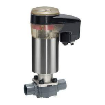
Motorized diaphragm valve
Hide thumbs
Also See for eSyDrive R649:
- Operating instructions manual (51 pages) ,
- Operating instructions manual (51 pages)

Related Manuals for GEM eSyDrive R649


Summary of Contents for GEM eSyDrive R649
- Page 1 GEMÜ R649 eSyDrive Motorized diaphragm valve Operating instructions further information webcode: GW-R649...
- Page 2 All rights including copyrights or industrial property rights are expressly reserved. Keep the document for future reference. © GEMÜ Gebr. Müller Apparatebau GmbH & Co. KG 26.09.2019 GEMÜ R649 2 / 41 www.gemu-group.com...
-
Page 3: Table Of Contents
19 Declaration of Incorporation according to 2006/42/ EC (Machinery Directive) ........... 38 20 Declaration of conformity according to 2014/68/EU (Pressure Equipment Directive) ......... 39 21 Declaration of conformity according to 2014/30/EU (EMC Directive) ............40 3 / 41 www.gemu-group.com GEMÜ R649... -
Page 4: General Information
Corrosive chemicals – Lists 1.3 Definition of terms Working medium Hot plant components! The medium that flows through the GEMÜ product. 1.4 Warning notes Wherever possible, warning notes are organised according to Rotating cover! the following scheme: SIGNAL WORD Possible... -
Page 5: Safety Information
13. Maintain the product correctly. 14. Do not carry out any maintenance work and repairs not described in this document without consulting the manu- facturer first. In cases of uncertainty: 15. Consult the nearest GEMÜ sales office. www.gemu-group.com 5 / 41 GEMÜ R649... - Page 6 Resets the network operation settings "INIT/CLOSE" Moves actuator to button the closed position Manual Starting initialisation operation Actuator switched off (OFF mode) Manual operation (on- site) Software update alternating On-site initialisation (buttons) Remote initialisation (via DigIn) GEMÜ R649 6 / 41 www.gemu-group.com...
-
Page 7: Correct Use
3.3.2 High visibility LEDs 3.4 Description The GEMÜ R649 2/2-way diaphragm valve has a hollow shaft actuator and is electrically operated. The eSyDrive hollow shaft actuator can be operated as an ON/OFF actuator or as an actuator with integrated positioner or process controller. -
Page 8: Order Data
FTF EN 558 series 1, ISO 5752, basic series 1, length only for body configuration D 5 Valve body material Code PVC-U, grey PP, reinforced PVDF Inliner PP-H, grey, outliner PP, reinforced Inliner PVDF/outliner PP, reinforced PP-H, natural 8 / 41 GEMÜ R649 www.gemu-group.com... - Page 9 5 Valve body material PVC-U, grey 6 Diaphragm material EPDM 7 Voltage/Frequency 24 V DC 8 Control module OPEN/CLOSE, positioner and process controller 9 Actuator version 2 A Actuator size 2 10 Mounting plate Without 9 / 41 www.gemu-group.com GEMÜ R649...
-
Page 10: Technical Data
Sealing at the valve seat and atmospheric sealing is ensured for the given values. Information on operating pressures applied on both sides and for high purity media on request. 10 / 41 GEMÜ R649 www.gemu-group.com... - Page 11 The Kv values for other product configurations (e.g. other diaphragm or body materials) may dif- fer. In general, all diaphragms are subject to the influences of pressure, temperature, the process and their tightening torques. Therefore the Kv values may exceed the tolerance limits of the stand- ard. 11 / 41 www.gemu-group.com GEMÜ R649...
- Page 12 Flange code 4, 39 2.36 3.08 3.20 MG = diaphragm size, weight in kg Operating time: Actuator version 0A adjustable, max. 6 mm/s Actuator version 01 adjustable, max. 6 mm/s Actuator version 2A adjustable, max. 4 mm/s 12 / 41 GEMÜ R649 www.gemu-group.com...
- Page 13 6.6.2 Digital input signals Digital inputs: Function: selectable using software Voltage: 24 V DC Logic level "1": >14 V DC Logic level "0": < 8 V DC Input current: typ. 2.5 mA (at 24 V DC) 13 / 41 www.gemu-group.com GEMÜ R649...
- Page 14 The actuator and the PC must be in the same network to use the web server. The IP address of the actuator is entered in the web browser and the actuator can then be parametrised. In order to use more than one actuator, a definitive IP address must be assigned to each actuator in the same network. 14 / 41 GEMÜ R649 www.gemu-group.com...
-
Page 15: Dimensions
82.0 132.0 172.0 243.0 40, 50 360.0 124.0 134.0 157.0 224.0 296.0 360.0 124.0 134.0 157.0 224.0 296.0 Dimensions in mm, MG = diaphragm size * CT = A + H1 (see body dimensions) 15 / 41 www.gemu-group.com GEMÜ R649... - Page 16 Code 30: Imperial butt weld spigot 2) Valve body material Code 1: PVC-U, grey Code 4: ABS Code 5: PP, reinforced Code 20: PVDF Code 71: Inliner PP-H, grey, outliner PP, reinforced Code 75: Inliner PVDF/outliner PP, reinforced 16 / 41 GEMÜ R649 www.gemu-group.com...
- Page 17 Dimensions in mm, MG = diaphragm size 1) Connection type Code 20: Spigot for IR butt welding 2) Valve body material Code 20: PVDF Code 71: Inliner PP-H, grey, outliner PP, reinforced Code 75: Inliner PVDF/outliner PP, reinforced 17 / 41 www.gemu-group.com GEMÜ R649...
- Page 18 Dimensions in mm, MG = diaphragm size 1) Connection type Code 7: Union end with DIN insert (socket) 2) Valve body material Code 1: PVC-U, grey Code 5: PP, reinforced Code 20: PVDF Code N5: PP-H, natural 18 / 41 GEMÜ R649 www.gemu-group.com...
- Page 19 Material code 1 øD ød 21.4 Dimensions in mm, MG = diaphragm size 1) Connection type Code 33: Union end with inch insert - BS (socket) 2) Valve body material Code 1: PVC-U, grey 19 / 41 www.gemu-group.com GEMÜ R649...
- Page 20 Code 33: Union end with inch insert - BS (socket) Code 3M: Union end with inch insert - ASTM (socket) Code 3T: Union end with JIS insert (socket) 2) Valve body material Code 1: PVC-U, grey Code 4: ABS 20 / 41 GEMÜ R649 www.gemu-group.com...
- Page 21 Dimensions in mm, MG = diaphragm size 1) Connection type Code 78: Union end with DIN insert (for IR butt welding) 2) Valve body material Code 5: PP, reinforced Code 20: PVDF Code N5: PP-H, natural 21 / 41 www.gemu-group.com GEMÜ R649...
- Page 22 Dimensions in mm, MG = diaphragm size 1) Connection type Code 78: Union end with DIN insert (for IR butt welding) 2) Valve body material Code 71: Inliner PP-H, grey, outliner PP, reinforced Code 75: Inliner PVDF/outliner PP, reinforced 22 / 41 GEMÜ R649 www.gemu-group.com...
- Page 23 G 2 3/4 2" 103.0 184.0 63.2 23.2 266.0 Dimensions in mm, MG = diaphragm size 1) Connection type Code 7R: Union end with Rp threaded socket insert 2) Valve body material Code 1: PVC-U, grey 23 / 41 www.gemu-group.com GEMÜ R649...
- Page 24 Code 4: Flange EN 1092, PN 10, form B, length FTF EN 558 series 1, ISO 5752, basic series 1 2) Valve body material Code 1: PVC-U, grey Code 5: PP, reinforced Code 20: PVDF Code 71: Inliner PP-H, grey, outliner PP, reinforced Code 75: Inliner PVDF/outliner PP, reinforced 24 / 41 GEMÜ R649 www.gemu-group.com...
- Page 25 Code 39: Flange ANSI Class 125/150 RF, face-to-face dimension FTF EN 558 series 1, ISO 5752, basic series 1, length only for body con- figuration D 2) Valve body material Code 1: PVC-U, grey Code 5: PP, reinforced Code 20: PVDF Code 71: Inliner PP-H, grey, outliner PP, reinforced Code 75: Inliner PVDF/outliner PP, reinforced 25 / 41 www.gemu-group.com GEMÜ R649...
- Page 26 Material code 1 ø D 27.5 12.5 55.0 Dimensions in mm, MG = diaphragm size 1) Connection type Code 2: Solvent cement socket DIN 2) Connection type Code 1: Threaded socket DIN ISO 228 26 / 41 GEMÜ R649 www.gemu-group.com...
- Page 27 100.0 see drawing Dimensions in mm, MG = diaphragm size For valve body material ABS (code 4) and connection type inch (code 30) the mounting bushes can be supplied as inch threads on request. 27 / 41 www.gemu-group.com GEMÜ R649...
-
Page 28: Manufacturer's Information
● chapter "Technical data"). Completely drain the plant. ● 4. Do not store solvents, chemicals, acids, fuels or similar fluids in the same room as GEMÜ products and their WARNING spare parts. Corrosive chemicals ▶ Risk of caustic burns Wear suitable protective gear. -
Page 29: Installation Position
3. Screw the threaded connections into the pipe in accord- ance with valid standards. 4. Screw the body of the product onto the piping using ap- propriate thread sealant. 5. Re-attach or reactivate all safety and protective devices. Fig. 4: Clamp connection www.gemu-group.com 29 / 41 GEMÜ R649... -
Page 30: Installation With Threaded Spigots
5. Clamp the product centrally between the piping with flanges. 6. Centre the gaskets. 7. Connect the valve flange and the piping flange using ap- propriate sealing materials and matching bolting. 8. Use all flange holes. GEMÜ R649 30 / 41 www.gemu-group.com... -
Page 31: Electrical Connection
Relay output K2, make contact Pin PE Function earth 10.2 Connection X2 5-pin M12 built-in socket, D-coded Signal name Pin 1 Tx + (Ethernet) Pin 2 Rx + (Ethernet) Pin 3 Tx - (Ethernet) www.gemu-group.com 31 / 41 GEMÜ R649... -
Page 32: Network Connection
● using the manual override. 12.2 Commissioning via the eSy-Web web interface 1. Disconnect the power supply. ● See separate eSy-Web operating instructions. 2. Turn housing cover 3 clockwise. 3. Remove housing cover 3. GEMÜ R649 32 / 41 www.gemu-group.com... -
Page 33: Inspection And Maintenance
4. Secure plant or plant component against recommission- ing. 5. Depressurize the plant or plant component. 5. Turn housing cover 3 anticlockwise. 6. Actuate GEMÜ products which are always in the same position four times a year. ð The product opens. 6. Turn housing cover 3 clockwise. - Page 34 6. Check parts for potential damage, replace if necessary leakage of the product. If the diaphragm is screwed in (only use genuine parts from GEMÜ). too far, perfect sealing at the valve seat will not be achieved. The function of the product is no longer en- 14.3 Removing the diaphragm...
- Page 35 10. Press the diaphragm face tightly onto the backing dia- tightness. phragm manually so that it returns to its original shape 9. Carry out initialisation. and fits closely on the backing diaphragm. 11. Align the weir of compressor and diaphragm in parallel. www.gemu-group.com 35 / 41 GEMÜ R649...
-
Page 36: Troubleshooting
Valve body / actuator damaged Replace valve body/actuator Body of the GEMÜ product is leaking Body of the GEMÜ product is faulty or Check the body of the GEMÜ product for corroded potential damage, replace body if... -
Page 37: Removal From Piping
3. Disassemble the product. Observe warning notes and goods can be processed only when this note is completed. If safety information. no return delivery note is included with the product, GEMÜ cannot process credits or repair work but will dispose of the 17 Disposal goods at the operator's expense. -
Page 38: Declaration Of Incorporation According To 2006/42/Ec (Machinery Directive)
19 Declaration of Incorporation according to 2006/42/EC (Machinery Directive) Declaration of Incorporation according to the EC Machinery Directive 2006/42/EC, Annex II, 1.B for partly completed machinery GEMÜ Gebr. Müller Apparatebau GmbH & Co. KG Fritz-Müller-Straße 6-8 74653 Ingelfingen-Criesbach, Germany declare that the following product Make: GEMÜ... -
Page 39: Declaration Of Conformity According To 2014/68/Eu (Pressure Equipment Directive)
AD 2000 Note for products with a nominal size ≤ DN 25: The products are developed and produced according to GEMÜ process instructions and quality standards which comply with the requirements of ISO 9001 and ISO 14001. According to Article 4, Paragraph 3 of the Pressure Equipment Directive 2014/68/EU these products must not be identified by a CE-label. -
Page 40: Declaration Of Conformity According To 2014/30/Eu (Emc Directive)
21 Declaration of conformity according to 2014/30/EU (EMC Directive) EU Declaration of Conformity according to 2014/30/EU (EMC Directive) GEMÜ Gebr. Müller Apparatebau GmbH & Co. KG Fritz-Müller-Straße 6-8 74653 Ingelfingen-Criesbach, Germany declare that the product listed below complies with the safety requirements of the EMC Directive 2014/30/EU. - Page 41 GEMÜ Gebr. Müller Apparatebau GmbH & Co. KG Subject to alteration Fritz-Müller-Straße 6-8, 74653 Ingelfingen-Criesbach, *88659161* Germany 09.2019 | 88659161 Phone +49 (0)7940 123-0 · info@gemue.de www.gemu-group.com...
Need help?
Do you have a question about the eSyDrive R649 and is the answer not in the manual?
Questions and answers