Table of Contents
Advertisement
Quick Links
NAV E 401 D and NAV E 201 D • Setup Guide
This guide provides instructions for an experienced installer to install the Extron NAV E 401 D and NAV E 201 D streaming encoder and to
make all connections. The Extron NAV encoder and one or more compatible decoders form an AV distribution and switching matrix on a
managed 1G IP network. The encoder fits in a standard US three-gang mud ring or electrical junction box. The encoder ships with a three-
gang mud ring and a decorator-style wallplate (white or black, depending on the version ordered). The front panel faceplates are in white or
black, as appropriate.
For more information on any subject in this guide, see the NAV E 401 D and NAV E 201 D User Guide, available at
NOTE:
www.extron.com
Features
Front Panel
NOTES:
•
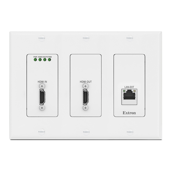
Figure 1 shows a NAV E 401 D. The NAV E 201 D is similar; the only
exception is lack of an Extension port (
C
F
•
Items
and
Connectors
HDMI IN port
Receives the HDMI video input (or DVI, with
A
—
an appropriate adapter) from the HDMI output port of the digital
video source (see
LockIt
securely fasten the HDMI connectors to the encoder).
HDMI OUT port — Outputs looped-through HDMI video for
B
local monitoring of the source signal.
C
Configuration (CONFIG) port —
for configuration of the encoder. The port uses IP over USB
; the IP address is always
technology
. The Config port is also discoverable via Toolbelt and Product Configuration Software (PCS).
be changed
NAV - Ext(ension) port (NAV E 401 D only) — If desired, connect another networked device to this port (see
D
connector
on page 7 to wire the connector). The port acts as a networked switch to the NAV 1G/PoE+ port (see
page 2).
Indicators and buttons
(LEDs that are always visible)
E
Visible LEDs
•
Power — Indicates power and startup status.
Blinking — The unit is receiving power, either locally or remotely (via PoE) and is booting up.
Lit steadily — The unit is receiving power, either locally or remotely (via PoE) and is operational.
•
HDMI — The encoder is detecting an HDMI input.
•
HDCP — The HDMI signal is HDCP encrypted.
•
Stream — Indicates the output status of the A/V stream.
Lit steadily – The encoder is actively streaming a NAV output consisting of video, audio, or both.
Blinking – The encoder is actively streaming a NAV output, but network errors are present.
F
Hidden buttons and LEDs (features that are visible only when the faceplate is removed) —
•
Reset button and LED — This recessed button and LED initiate and display three modes of reset (see the NAV E 401 D and
NAV E 201 D User Guide, available at
•
ID button and LED — The recessed ID button identifies the encoder when pressed. The LED blinks when the encoder is in
pairing mode (see
•
NAV 1G LEDs — Indicate the status of the network connection.
Link LED — Lit steadily indicates that a network link is established. Blinking indicates a link speed less than 1Gbps.
Act LED — Blinking indicates network traffic. The blink rate corresponds to activity.
.
D
.
)
are
visible only when the faceplate is removed
Lacing Brackets
on page 7 to
®
Connect a PC into the encoder
203.0.113.22 and CANNOT
—
www.extron.com
Pairing devices on front panel
E E
E
PWR
HDMI HDCP
F
F F
.
HDMI IN
A
A A
Figure 1.
NAV E 401 D Front Panel Features
, for details).
on page 7 for details).
STRM
RESET
ID
HDMI OUT
NAV 1G
NAV - EXT
LNK
ACT
CONFIG
E
C
C C
B
B B
LAN and Ext
NAV E 401 D
D
D D
only
on
A
1
Advertisement
Table of Contents

Related Manuals for Extron electronics NAV E 401 D


Summary of Contents for Extron electronics NAV E 401 D
- Page 1 NAV E 401 D and NAV E 201 D • Setup Guide This guide provides instructions for an experienced installer to install the Extron NAV E 401 D and NAV E 201 D streaming encoder and to make all connections. The Extron NAV encoder and one or more compatible decoders form an AV distribution and switching matrix on a managed 1G IP network.
-
Page 2: Rear Panel Connectors
NAV E 401 D and NAV E 201 D • Setup Guide (Continued) Rear Panel Connectors NAV 1G/PoE+ port Connects to an Ethernet LAN on which — one or more decoders also reside for streaming and control (see LAN and Ext connector on page 7 to wire the connector). -
Page 3: Site Preparation
Site preparation The encoder fits into a standard US three-gang junction box or mud ring and decorator- Wall style wallplate. The encoder ships with a mud ring. Optional UL Listed junction boxes, external junction boxes, and surface mounting boxes are available for use with the unit. Read any installation instructions and UL guidelines that come with the mounting devices, then install the box or mud ring in the opening at the installation site. -
Page 4: System Operation
NAV E 401 D and NAV E 201 D • Setup Guide (Continued) Wall Stud Metal Junction Box Flush with Wall Surface Mounting Screws (6 Plcs) NAV E 201 D NOTE: Ensure that the vent holes on the top and bottom of the encoder remain unobstructed. - Page 5 Connection via web pages Connection to the encoder and its embedded web pages can be made via either the front panel Configuration (USB) port (using IP over figure 1 figure 2 USB technology) (see on page 1) or the rear panel NAV 1G/PoE+ port (see on page 2).
-
Page 6: Connection Settings
1 1 1 1 Figure 7. Home Page Detailed descriptions of communication, configuration, and NOTE: monitoring are provided in the NAV E 401 D and NAV E 201 D User www.extron.com Guide, available at Connection settings View and change connection settings as follows: On the home page, click Settings (see figure 7, ) >... -
Page 7: Connection Details
Pairing devices on front panel Pair devices from the front panel as follows: Use a Tweeker or other small screwdriver to press and hold the encoder ID button on the front panel, behind the bezel (see figure 1 on page 1) for approximately 3 seconds, until the ID LED blinks. The encoder enters pairing mode, which allows decoders to receive AV streams from encoders. - Page 8 For information on safety guidelines, regulatory compliances, EMI/EMF compatibility, accessibility, and related topics, see the Extron Safety and Regulatory Compliance Guide on the Extron website. www.extron.com © 2020 Extron — All rights reserved. 68-2978-50 Rev. A All trademarks mentioned are the property of their respective owners. 11 20 Worldwide Headquarters: Extron USA West, 1025 E.
Need help?
Do you have a question about the NAV E 401 D and is the answer not in the manual?
Questions and answers