
Related Manuals for Extron electronics NAV E 401 D


Summary of Contents for Extron electronics NAV E 401 D
- Page 1 User Guide NAV Pro AV Over IP NAV E 401 D and NAV E 201 D Streaming HDMI Encoders 68-2978-01 Rev. A 01 22...
- Page 2 Safety Instructions Safety Instructions • English WARNING: This symbol, , when used on the product, is intended to alert the user of the presence of uninsulated dangerous voltage within the product’s enclosure that may present a risk of electric shock. ATTENTION: This symbol, , when used on the product, is intended...
- Page 3 Copyright © 2022 Extron. All rights reserved. www.extron.com Trademarks All trademarks mentioned in this guide are the properties of their respective owners. The following registered trademarks ( ® ), registered service marks ( ), and trademarks ( ) are the property of RGB Systems, Inc. or Extron (see Terms of Use page at www.extron.com): the current list of trademarks on the...
- Page 4 FCC Class A Notice This equipment has been tested and found to comply with the limits for a Class A digital device, pursuant to part 15 of the FCC rules. The Class A limits provide reasonable protection against harmful interference when the equipment is operated in a commercial environment.
- Page 5 Conventions Used in this Guide Notifications The following notifications are used in this guide: CAUTION: Risk of minor personal injury. ATTENTION : Risque de blessure mineure. ATTENTION: • Risk of property damage. • Risque de dommages matériels. NOTE: A note draws attention to important information. TIP: A tip provides a suggestion to make working with the application easier.
-
Page 7: Table Of Contents
Power ..............17 Alarms ..............68 Pairing Devices ........... 17 Operation ............18 System operation with a NAVigator ....18 Configuration and other operations ....18 Reset operations ..........18 NAV E 401 D and NAV E 201 D Encoders • Contents... - Page 8 NAV E 401 D and NAV E 201 D Encoders • Contents viii...
-
Page 9: Introduction
NOTE: In this guide: • The NAV E 401 D and NAV E 201 D are both referred to as an “encoder.” They are referenced by model name when differences exist. •... -
Page 10: About The Decoder
The external 100 VAC to 240 VAC, 50-60 Hz power supply provides worldwide power compatibility. NAV E 401 D and NAV E 201 D Encoders • Introduction... -
Page 11: Features
HDCP-compliant devices. • (NAV E 401 D only) Ethernet extension — Built-in Ethernet extension facilitates connection to peripheral Ethernet-enabled devices over the same cable as video and audio. Saves on cabling cost in installations with any remote devices requiring LAN connectivity. - Page 12 • Mounts in an included 3-gang decorator-style wallplate — The 3-gang decorator- style wallplate is available in black or white to blend with a wide range of environments. NAV E 401 D and NAV E 201 D Encoders • Introduction...
-
Page 13: Installation
Connector and Cable Details • Mounting and Rear Panel Connections The NAV E 401 D and NAV E 201 D encoder can be installed in the provided three-gang mud ring or a compatible junction box. A decorator-style wallplate cover is supplied. -
Page 14: Installing The Optional Wall Box
For guidelines, see sections 307 (“Protruding Objects”) and 308 (“Reach Ranges”) of the 2010 ADA Standards for Accessible Design available at: http://www.ada.gov/regs2010/2010ADAStandards/2010ADAStandards.pdf. NAV E 401 D and NAV E 201 D Encoders • Installation... - Page 15 NOTE: Read any installation instructions and UL guidelines that come with the mounting devices, then install the box or mud ring in the opening at the installation site. NAV E 401 D and NAV E 201 D Encoders • Installation...
- Page 16 Trim back and insulate exposed cable shields with heat shrink to reduce the chance of short circuits. The outer foil shield can be cut back to the point where the cable exits the cable clamp. NAV E 401 D and NAV E 201 D Encoders • Installation...
-
Page 17: Make Rear Panel Connections
CONTROL 2.0A MAX Figure 4. NAV E 401 D and NAV E 201 D Rear Panel Connectors NAV 1G/PoE+ port — Connect to an Ethernet LAN on which one or more decoders also reside for streaming and control (see LAN and Ext connector on page 14 to wire the connector). -
Page 18: Complete The Physical Installation
Attach the faceplate to the encoder: insert the six included screws through the circular holes in the faceplate and the tabs on the encoder. Tighten the screws using a flat bladed screwdriver until snug. NAV E 401 D and NAV E 201 D Encoders • Installation... -
Page 19: Connectors
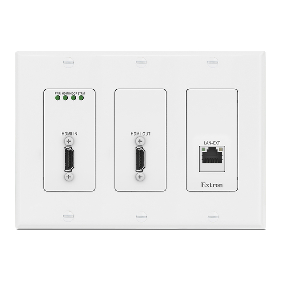
NAV E 401 D and NAV E 201 D Front Panel Features NOTES: • Figure 6 shows a NAV E 401 D. The NAV E 201 D is similar; the only exception is lack of an Extension port (D). •... -
Page 20: Indicators And Buttons
Lit steadily — Indicates that a network link is established at 1 Gbps. Blinking – Indicates that network link is established less than 1 Gbps. Act LED — Blinking indicates network traffic. The blink rate corresponds to activity. NAV E 401 D and NAV E 201 D Encoders • Installation... -
Page 21: Connector And Cable Details
( While holding the connector securely against the lacing bracket, use pliers or similar tools to tighten the tie wrap, then remove any excess length ( NAV E 401 D and NAV E 201 D Encoders • Installation... -
Page 22: Control Connector Wiring
TIA/EIA T568-B wiring standard (see figure 9). Pins: 12345678 TIA/EIA T568B Wire color White-orange Orange White-green Blue White-blue Green White-brown Brown TP Wires Figure 9. RJ-45 Connector and Pinout Table NAV E 401 D and NAV E 201 D Encoders • Installation... -
Page 23: Power Supply Wiring
Ne pas étamer les conducteurs avant de les insérer dans le connecteur. Les câbles étamés ne sont pas aussi bien fixés dans le connecteur et pourraient être retirés. NAV E 401 D and NAV E 201 D Encoders • Installation... - Page 24 15) permettent de repérer le pôle négatif du cordon d’alimentation. To verify the polarity before connection, plug in the power supply with no load and check the output with a voltmeter. NAV E 401 D and NAV E 201 D Encoders • Installation...
-
Page 25: Basic Operation
Use a Tweeker or other small screwdriver to press and release the encoder front panel ID button. The encoder exits pairing mode. Repeat steps 1 through 4 to pair decoders to other encoders. NAV E 401 D and NAV E 201 D Encoders • Basic Operation... -
Page 26: Operation
1 to mode 5. • The modes listed close all open IP and other connections and close all sockets. NAV E 401 D and NAV E 201 D Encoders • Basic Operation... - Page 27 Removes the initial serial number passwords and sets them password to extron. on page 64. to extron. The reset LED blinks four times in succession during the reset. NAV E 401 D and NAV E 201 D Encoders • Basic Operation...
- Page 28 Figure 11. Resets Release the RESET button and then immediately press and release the RESET button again. Nothing happens if you do not momentarily RESET within 1 second. NAV E 401 D and NAV E 201 D Encoders • Basic Operation...
-
Page 29: Html Operation
If you use IP over USB, Extron recommends waiting a minute after plugging in the cable for your PC to identify the USB connection as a valid Ethernet port. NAV E 401 D and NAV E 201 D Encoders • HTML Operation... - Page 30 In the event of a complete system reset, the passwords revert to the default. • The default username is and the default password is admin extron • Passwords are case sensitive. NAV E 401 D and NAV E 201 D Encoders • HTML Operation...
- Page 31 £ £ £ £ £ £ £ £ £ £ £ £ ¦ ¦ ¦ ¦ ¦ ¦ ¦ ¦ ¦ ¦ ¦ ¦ ¦ ¦ ¦ ¦ ¦ ¦ Figure 14. Home Page NAV E 401 D and NAV E 201 D Encoders • HTML Operation...
-
Page 32: Using The Html Pages
ABOUT link — Opens a pane that provides information about the encoder (see About ¦ Page on page 57). NAV E 401 D and NAV E 201 D Encoders • HTML Operation... -
Page 33: Input Configuration Page
) in the appropriate pane. The pane opens (see Video Video pane on page 26). NOTE: For the Audio pane, the EDIT button ( ) is not available for selection. NAV E 401 D and NAV E 201 D Encoders • HTML Operation... - Page 34 This feature is typically used when EDID slot 6 (loop-thru monitor) or 7 (decoder output) is selected to save the EDID from a connected display. NAV E 401 D and NAV E 201 D Encoders • HTML Operation...
-
Page 35: Output Configuration Page
Output Configuration Stream Loop Thru Test ), and ) that display the status of Pattern AES67 Audio On Screen Display the streamed output. NAV E 401 D and NAV E 201 D Encoders • HTML Operation... - Page 36 NOTE: The AES67 standard allows for interoperability among AES67 capable devices. Enabling AES67 audio allows the device to transmit a audio stream to a third-party AES67 capable receiver. NAV E 401 D and NAV E 201 D Encoders • HTML Operation...
- Page 37 NOTE: Allow Audio Only must be disabled to use the NAV screen saver (see Screen Display (OSD) pane on page 32). NAV E 401 D and NAV E 201 D Encoders • HTML Operation...
- Page 38 Loop Thru (see item on page 11) and streamed outputs: • Disabled (no test pattern) • Color Bar • Grayscale NAV E 401 D and NAV E 201 D Encoders • HTML Operation...
- Page 39 ( ) are based on the encoder MAC address. Audio Address — Click in the Audio Address field and directly enter a new address as necessary. NAV E 401 D and NAV E 201 D Encoders • HTML Operation...
- Page 40 33) for a period of time set by the Screen Saver Duration setting, NOTE: Allow Audio Only (see , Allow Audio only on page 29) must be disabled to use a screen saver. NAV E 401 D and NAV E 201 D Encoders • HTML Operation...
- Page 41 1080P image and the output is 4K, you will see black boarders. • If you have not already uploaded an image, the pane displays the Select File button (see Upload a custom image on page 34). NAV E 401 D and NAV E 201 D Encoders • HTML Operation...
- Page 42 2 2 2 2 2 2 2 2 2 2 2 2 NOTE: Click ) to delete the image. This action is necessary to replace the custom image. NAV E 401 D and NAV E 201 D Encoders • HTML Operation...
-
Page 43: Ties Page
The proxied decoder HTML page behaves as described in the guide for the decoder (see the applicable decoder guide available at www.extron.com). NAV E 401 D and NAV E 201 D Encoders • HTML Operation... -
Page 44: Tools Pages
NOTE: Unless otherwise directed, the encoder backup file goes to the Downloads folder of the connected PC. Click Keep to save the file to the folder or Discard as desired. Downloads NAV E 401 D and NAV E 201 D Encoders • HTML Operation... - Page 45 Navigate to the folder where the Restore file is saved (typically the folder) Downloads (see figure 29, ). Select the file. Click ). The page returns to the top (see figure 30 on page 38). Device Tools Open NAV E 401 D and NAV E 201 D Encoders • HTML Operation...
- Page 46 When the operation completes, the encoder reboots. NOTE: You must reconnect to the encoder (see Opening the Embedded HTML Pages on page 21) if you have other operations to perform. NAV E 401 D and NAV E 201 D Encoders • HTML Operation...
- Page 47 Click ). The dialog box closes and the pane returns to the top, with Open Open Tools the selected firmware file identified (see figure on page 40). NAV E 401 D and NAV E 201 D Encoders • HTML Operation...
- Page 48 3 3 3 3 4 4 4 4 4 4 4 4 4 4 4 4 4 4 4 4 4 4 Figure 35. Tools — Reset Function NAV E 401 D and NAV E 201 D Encoders • HTML Operation...
- Page 49 Any of these operations concludes, with the encoder rebooting. NOTE: You must reconnect to the encoder (see Opening the Embedded HTML Pages on page 21) if you have other operations to perform. NAV E 401 D and NAV E 201 D Encoders • HTML Operation...
- Page 50 Figure 37 shows the typical results of a Trace diagnostic. Figure 37. Trace Results Shown ) to reset the Address field if you want to run another diagnostic. Click CLEAR ( NAV E 401 D and NAV E 201 D Encoders • HTML Operation...
-
Page 51: Monitoring Page
NAV E 401 D only Figure 38. Monitoring Page IGMP Querier Primary Controller Memory Utilization Alarms AV LAN Utilization Download Logs Ethernet Extension Utilization (NAV E 401 D only) NAV E 401 D and NAV E 201 D Encoders • HTML Operation... - Page 52 51) or enabled with nothing connected to it. Ethernet Extension Normal Indication Ethernet Extension Disabled or Not Connected Figure 40. Ethernet Extension Utilization Pane Indications NAV E 401 D and NAV E 201 D Encoders • HTML Operation...
- Page 53 Click the All checkbox ( ) or individual endpoint checkboxes ( ) to select one or more alarms to clear. Click CLEAR ALARMS ( ) to clear this alarm. NAV E 401 D and NAV E 201 D Encoders • HTML Operation...
- Page 54 The encoder monitors the active alarm states of all devices in the NAV system. All alarm state changes are logged even if status reporting is disabled from the encoder. NAV E 401 D and NAV E 201 D Encoders • HTML Operation...
-
Page 55: Settings Page
Hyphens are allowed in any other position. character. • Cannot begin with a space. • Multiple tags are allowed, making filtering • Spaces are allowed after the first character. and sorting searching easier. NAV E 401 D and NAV E 201 D Encoders • HTML Operation... - Page 56 Location — Click in this field and type in a location to customize your system. SAVE and CANCEL buttons — Click SAVE to take changes or Device Details CANCEL to abandon them. Clicking either button closes the editable pane. NAV E 401 D and NAV E 201 D Encoders • HTML Operation...
- Page 57 Date | Time — Click in this field and type in the date and time. Time Zone — Click the drop-down list to select the offset from Coordinated Universal Time (UTC). NAV E 401 D and NAV E 201 D Encoders • HTML Operation...
- Page 58 NTP server — Click in these fields and type in the IP address or DNS name of an NTP server. SAVE and CANCEL buttons — Click SAVE to take changes or CANCEL to Date & Time abandon them. Clicking either button closes the editable pane. NAV E 401 D and NAV E 201 D Encoders • HTML Operation...
- Page 59 1 1 1 1 1 1 1 1 1 1 1 1 1 1 1 1 1 1 NAV E 401 D only Figure 51. Network Connection Pane NAV E 401 D and NAV E 201 D Encoders • HTML Operation...
- Page 60 ) — DHCP is on by default. When a DHCP server is not accessible, the Link local IP Address is available. • MAC Address ( ) — A unique read-only identifier for network connected devices. NAV E 401 D and NAV E 201 D Encoders • HTML Operation...
- Page 61 SAVE and CANCEL buttons — Click SAVE ( ) to take change or CANCEL to Password abandon it. Clicking either button closes the editable pane. NAV E 401 D and NAV E 201 D Encoders • HTML Operation...
- Page 62 SAVE and CANCEL buttons — Click SAVE to take Port changes or CANCEL to abandon them. Clicking either button closes the editable pane. NAV E 401 D and NAV E 201 D Encoders • HTML Operation...
- Page 63 Link Layer Discovery Protocol (LLDP) — LLDP, a vendor-neutral protocol, is used by network devices to discovery, identify and share information between two directly connected network devices. Click to toggle LLDP on and off. NAV E 401 D and NAV E 201 D Encoders • HTML Operation...
- Page 64 SAVE and CANCEL buttons — Click SAVE to take changes or CANCEL to abandon them. Clicking either button closes the editable pane. NAV E 401 D and NAV E 201 D Encoders • HTML Operation...
-
Page 65: About Page
Firmware version number, which is current NAV firmware version running. Installed licenses, which can be sorted by clicking the desired filtering letter. NAV E 401 D and NAV E 201 D Encoders • HTML Operation... -
Page 66: Control System
, and Ping Reset Reboot • Configure 802.1x security settings View 802.1x status logs • • Update the firmware to a selected device or group of devices NAV E 401 D and NAV E 201 D Encoders • Control System... - Page 67 Contact your IT administrator for more information on what tools and policies are required to obtain or create the SSL certificate and, if necessary, the corresponding passphrase. NAV E 401 D and NAV E 201 D Encoders • Control System...
-
Page 68: Global Configurator Plus And Professional
Control Professional Certification. For detailed descriptions and procedures to setup a control system with an IPCP Pro device and Global Configurator, see the applicable Global Configurator Help file. NAV E 401 D and NAV E 201 D Encoders • Control System... -
Page 69: Global Scripter
Python and should know how to use Extron ControlScript. For detailed descriptions and procedures to setup a control system with an IPCP Pro device and Global Scripter, see the Global Scripter Help File. NAV E 401 D and NAV E 201 D Encoders • Control System... -
Page 70: Sis Operation
The HDMI Out hot plug connection is changed. is plugged and is unplugged. In<status> A change in signal input status has occurred. is input detected and is no input. NAV E 401 D and NAV E 201 D Encoders • SIS Operation... -
Page 71: Encoder Error Responses
= Carriage return (no line feed) = Pipe (can be used interchangeably with the character) • = space = Escape key = Can be used interchangeably with the character NAV E 401 D and NAV E 201 D Encoders • SIS Operation... -
Page 72: Sis Command And Response Tables
No blank or space characters are permitted as part of a name. The first character must be a letter, and the last character must not be a minus sign/hyphen = Device number 0001 — 4096 NAV E 401 D and NAV E 201 D Encoders • SIS Operation... - Page 73 Multicast IP 00 — = Dropped packets (in percent) = IP address, subnet, or gateway address xxx.xxx.xxx.xxx = Serial number < xxxxxxx > • = Internal temperature NAV E 401 D and NAV E 201 D Encoders • SIS Operation...
- Page 74 Read full firmware version — Advanced Part number View part number 60-xxxx-xx X1& KEY: = Firmware version = Full firmware version xxxx = Full firmware version — advanced xxxx-bnnn NAV E 401 D and NAV E 201 D Encoders • SIS Operation...
- Page 75 = On, enabled, detected = IP address, subnet, or gateway address xxx.xxx.xxx.xxx = Subnet prefix Number of bits used to create the subnet = MAC address xx.xx.xx.xx.xx.xx NAV E 401 D and NAV E 201 D Encoders • SIS Operation...
-
Page 76: Troubleshooting
An assigned NAVigator is not discovered Check the offline NAVigator for a power Device Offline on the network. failure. Check the network connectivity of the endpoint. NAV E 401 D and NAV E 201 D Encoders • Troubleshooting... - Page 77 NAV device cannot synchronize its Ensure that network policies allow PTP Sync PTPv2 clock with any peers. PTPv2 packets to reach the NAV Device from a clock master. NAV E 401 D and NAV E 201 D Encoders • Troubleshooting...
- Page 78 The input is changed and video sync Debug the connectivity of the AV source Video loss cannot be established for within a two- device to the NAV encoder. second window. NAV E 401 D and NAV E 201 D Encoders • Troubleshooting...
- Page 79 Extron Electronics makes no further warranties either expressed or implied with respect to the product and its quality, performance, merchantability, or fitness for any particular use. In no event will Extron Electronics be liable for direct, indirect, or consequential damages resulting from any defect in this product even if Extron Electronics has been advised of such damage.
Need help?
Do you have a question about the NAV E 401 D and is the answer not in the manual?
Questions and answers