
Related Manuals for Extron electronics Quantum Elite Series


Summary of Contents for Extron electronics Quantum Elite Series
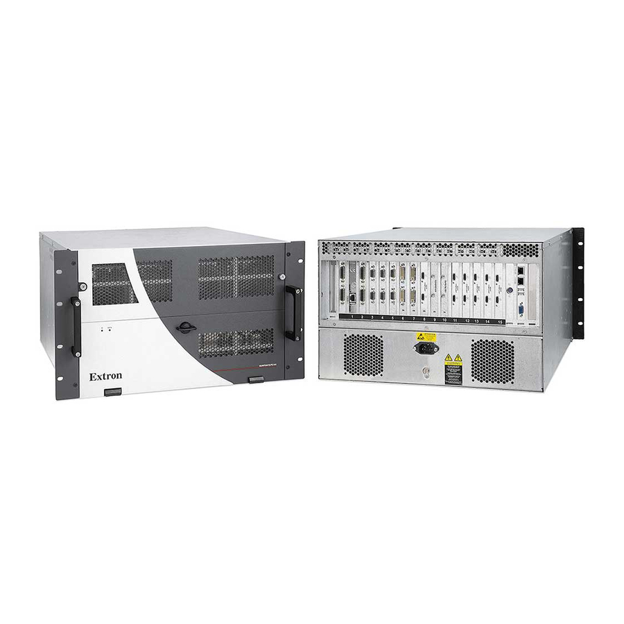
- Page 1 User Guide Quantum Processors ® Quantum Elite and Quantum Connect Videowall Processing Systems 68-2010-01 Rev. E 12 19...
- Page 2 Safety Instructions Safety Instructions • English Istruzioni di sicurezza • Italiano AVVERTENZA: Il simbolo, , se usato sul prodotto, serve ad WARNING This symbol, , when used on the product, is intended to avvertire l’utente della presenza di tensione non isolata pericolosa alert the user of the presence of uninsulated dangerous voltage within the all’interno del contenitore del prodotto che può...
- Page 3 Copyright © 2011-2020 Extron Electronics. All rights reserved. www.extron.com Trademarks All trademarks mentioned in this guide are the properties of their respective owners. The following registered trademarks ( ® ), registered service marks ( ), and trademarks ( ) are the property of RGB Systems, Inc. or Extron Electronics (see the current list of trademarks on the...
- Page 4 FCC Class A Notice This equipment has been tested and found to comply with the limits for a Class A digital device, pursuant to part 15 of the FCC rules. The Class A limits provide reasonable protection against harmful interference when the equipment is operated in a commercial environment.
- Page 5 Conventions Used in this Guide Notifications The following notifications are used in this guide: Potential risk of severe injury or death. WARNING: AVERTISSEMENT : Risque potentiel de blessure grave ou de mort. CAUTION: Risk of minor personal injury. ATTENTION : Risque de blessure mineure. ATTENTION: •...
-
Page 7: Table Of Contents
Contents Introduction Operation .............. 61 ............3 Powering On and Off ........61 About this Guide ..........3 About the Quantum Videowall Processors ..3 Using the Control Panel ........63 Starting the Control Panel ......63 Models ............4 Features ............. - Page 8 Reference Information ........80 Mounting ............80 UL Guidelines for Rack Mounting ....80 Rack Mounting the Quantum Processor ..81 Mounting the QC 101 ........82 Network Setup ..........83 What is an IP Address?......... 83 Choosing IP Addresses ........ 83 Subnet Mask ..........
-
Page 9: Introduction
Introduction This section gives an overview of the Extron Quantum Videowall Processors, describes significant features of the series, and provides sample application diagrams. The following topics are covered: • About this Guide About the Quantum Videowall Processors • • Features Functional Overview •... -
Page 10: Models
Models Quantum Elite • The Quantum Elite 615 has a 6U high, 15-slot card frame. It has a maximum input capacity of 28 single-link DVI-D, 28 HDMI, 28 SDI, 28 RGB or HD component video, or 168 composite or S-video. Maximum output capacity is 28 DVI-I or HDMI. Multiple Quantum Elite 615 card cages can be used to create very large display arrays. - Page 11 Quantum Elite: • DVI input: The dual DVI-D input card accepts two digital or analog DVI sources at resolutions up to 1920x1200 and HDTV 1080p @ 60 Hz as well as custom resolutions. • SDI input: The dual SDI input card accepts two 3G-SDI, HD-SDI, or SD-SDI sources in any combination at 480i, 576i, 720p, 1080i, and 1080p resolutions.
- Page 12 Image up-scaling and down-scaling — High performance image scaling • technology provides high quality up-scaling and down-scaling of high resolution RGB or HD video signals. • Solid state flash storage (Quantum Elite 615 only) — The Quantum Elite 615 model features CompactFlash-based data storage for the operating system and image files.
-
Page 13: Functional Overview
USB port — Two USB ports are provided to access image files on a USB flash drive • or to connect a USB keyboard and mouse to access the Quantum Control Panel. Motion adaptive deinterlacing — The SDI input card provides motion adaptive •... - Page 14 Maximum Number of Real Time Sources Source Type Sampling Deinterlacing At 50 Hz At 60 Hz Single field – NTSC 4:2:2 Three field – Single field – PAL/SECAM 4:2:2 Three field – HD 1080i Single field 4:4:4 Three field HD 1080p 4:4:4 HD 720p 4:4:4...
-
Page 15: Display Architecture
High-definition sources Maximum Number of Resolution Real Time Sources Full native HD 720p Quarter Full native HD 1080p Quarter Display Architecture When Quantum is controlled by the Quantum Control Software, source signals are placed on the display in windows, which are fully resizable and can be positioned anywhere on the displays. -
Page 16: Scenario Examples
Rectangulation Limit (RAPT Source Layer) There is no limit to the number of source windows that can be placed on the PCI source layer. However, the maximum number of windows that can be displayed at one time on the RAPT source layer is dependent on a rectangulation limit, which is the maximum number of rectangles needed to draw the display layout. - Page 17 Scenario 1 — Maximum number of video sources on a single screen Screen layout — Scenario 1 In this scenario, a single 1600x1200 display device displays 128 video source windows. Figure 2. Example of a Single 1600x1200 Display Showing the Maximum Number of Windows Possible on One Screen Because each window is smaller than the native source resolution, the input card scales each source down to the required size.
- Page 18 Expansion Options — Scenario 1 On the Quantum Elite 615, you have three spare card slots to which you can add more input cards, increasing the choice of sources. Alternatively, you can add output cards to spread out the windows and increase their size. Scenario 2 —...
- Page 19 Expansion options — Scenario 2 With the Quantum Elite 615, you have five spare card slots to which you can add more output cards to provide more screens, or you can add more input cards to increase the choice of sources. NOTE: Increasing the number of full resolution source windows exceeds the real time limit of the RAPT bus, so the Quantum uses its bandwidth management scheme.
- Page 20 System capacity — Scenario 3 Figure 7. System Capacity for Scenario 3 The limit of 144 real time video source windows is imposed by the maximum number of card slots being used. Expansion options — Scenario 3 Assuming that all video sources are using single-field deinterlacing, approximately 50 percent of the RAPT bandwidth is being used.
- Page 21 Hardware requirements — Scenario 4 • 4 output cards driving 8 UXGA screens 11 input cards providing 132 source inputs • • A Quantum Elite 615 card frame. System capacity — Scenario 4 Figure 9. System Capacity for Scenario 4 The limit of 132 real time video source windows is imposed by the maximum number of card slots being used.
-
Page 22: Application Diagrams
Application Diagrams The following application diagrams show examples of how the Quantum Connect and Quantum Elite can be connected. 4K Display Control PC 1 2 3 4 WiFi Extron HDMI HDMI Quantum Connect Control Software DATA Extron Quantum Connect 84 HDCP-Compliant Videowall Processor QUANTUM CONNECT 408... - Page 23 HDCP-Compliant Displays Quantum Elite Control Software HDMI HDMI Control VLAN Control Software can select: Display Presets Source Changes in Windows Window Borders Color and Style Text Insertion POWER DATA Extron Quantum Elite HDCP-compliant Scalable Videowall Processing System QUANTUM ELITE CCTV Cameras Composite or S-video Blu-ray Player HDMI...
- Page 24 HDCP-Compliant Displays Extron TLP 1000 TV 10" TouchLink Tabletop Touchpanel Ethernet Ethernet HDMI HDMI Control VLAN Ethernet Ethernet Quantum Elite Control Software WARNING SEE USER GUIDE BEFORE USING THIS EQUIPMENT DO NOT REMOVE THIS PANEL NO USER-SERVICEABLE PARTS INSIDE REFER ALL SERVICING TO QUALIFIED SERVICE PERSONNEL THIS EQUIPMENT MUST BE GROUNDED/EARTHED...
- Page 25 HDMI HDMI Extron QC 101 E Controller for Quantum Elite 100-240V ~ --A MAX OUTPUTS REMOTE OUTPUTS RESET POWER DISPLAYPORT POWER DATA Tx Rx G RS232 HDMI RGBHV 50/60 Hz QUANTUM ELITE Ethernet RS-232 Extron Quantum Elite 615 HDCP-Compliant Videowall Processing System IPCP PRO 250 Control...
-
Page 26: Installation And Maintenance
Installation and Maintenance This section provides the steps to install the Quantum processor. It also describes the rear panel components and provides instructions for cabling. The following topics are included: • Installation Steps Rear Panel Features • • Card Connections and Functions •... - Page 27 Set the Quantum power switch or switches to On. (The power switches are on the front panel behind the access door. See Front Panel Features, beginning on page 52.) WARNING: To avoid the risk of electric shock or product damage due to condensation, always allow the Quantum processor to become acclimated to ambient temperature and humidity for at least 30 minutes before switching it on.
-
Page 28: Rear Panel Features
Rear Panel Features The Quantum rear panels provide slots for cards containing video input and output connectors, RJ-45 network connectors, connectors for a keyboard, mouse, and monitor, and USB connectors. It also contains the power connector and two vents. Quantum Elite 615 Rear Panel The Quantum Elite 615 rear panel has 15 slots in which cards can be installed to order, plus three slots in which cards are permanently installed. - Page 29 Input and output cards — The slots numbered 2 through 15 on the rear panel contain input and output cards. When you order the Quantum, you specify the desired number and type of input cards and output cards. You receive the system with all cards installed.
-
Page 30: Quantum Elite 408 And Quantum Connect Rear Panels
Quantum Elite 408 and Quantum Connect Rear Panels The Quantum Elite 408 and Quantum Connect 84 and 82 rear panels have 11 slots in which cards are installed: • Quantum Elite 408 — Has eight slots in which cards can be installed to order, plus three slots in which cards are permanently installed. - Page 31 Power connector — Connect the supplied IEC power cord between this male IEC connector and an AC power source. (A power switch on the front panel powers the unit on and off.) Unused slots — No cards are installed in these slots. Control card —...
-
Page 32: Card Connections And Functions
Card Connections and Functions This section describes the cards that can be installed in the Quantum processor and provides instructions for connecting to the ports on each card, along with a connection example for each. Control Card The Control card is installed in the second slot from the left in all models. Connect a computer that is running the Quantum Control Software to the fast Ethernet (100Base-T) Control port on this card to enable you to control the Quantum processor and to set up videowall applications via the computer. - Page 33 Control Port Ethernet 100Base-T Quantum Elite ATTENTION OBSERVE PRECAUTIONS FOR HANDLING ELECTROSTATIC SENSITIVE DEVICES Control Software Crossover Cable WARNING SEE USER GUIDE BEFORE USING THIS EQUIPMENT DO NOT REMOVE THIS PANEL NO USER-SERVICEABLE PARTS INSIDE REFER ALL SERVICING TO QUALIFIED SERVICE PERSONNEL THIS EQUIPMENT MUST BE GROUNDED/EARTHED DO NOT OBSTRUCT...
-
Page 34: Input Cards
Input Cards Analog and digital video sources such as computers, cameras, Blu-ray™ or DVD players, and video servers are input to the Quantum processor through one or more of the Quantum input cards. These cards provide digitization, deinterlacing, and down-scaling of sources as well as full source auto-detection. - Page 35 1/16 of the original source (horizontally, vertically, or both). For simplicity, the example in the diagram below assumes that each screen in the target display has the same resolution as the source. Card Outputs a Ruth Dire Unity Image Extron Electronics Ruth Dire Extron Electronics Input RAPT Output...
- Page 36 Video/S-video input card (Quantum Elite only) The Video/S-video input card enables you connect up to 12 composite video sources, S-video (YC) sources, or both types in combination. You can connect input devices to one or both connectors via one or two of the provided breakout adapter cables. The Quantum Elite 615 card frame can accommodate up to 14 Video/S-video input cards, allowing up to 168 video source inputs.
- Page 37 Connecting composite video sources • Input connectors: The Video/S-video input card contains two female 26-pin D type connectors, to which the breakout cables are attached for composite video or S-video. • Breakout cables (adapters): Each of the two provided breakout cables has a male 26-pin, high-density, D-type connector attached to 12 flying leads terminated in BNC connectors (see the figure 20...
- Page 38 NOTE: The breakout cable connected to the bottom connector on the Video/S-video input card should have only the C cables of S-video devices attached. Repeat step 2 for any additional S-video devices that you want to connect. Connector pin assignments Top connector: Function Function...
- Page 39 Video and S-video connection example The diagram below shows an example of composite and S-video sources connected to the Video/S-video input card via breakout cables. Video Input Card Composite Video Breakout Cable or Y of S-video Breakout Cable C of S-video Only Composite Composite TUNER...
- Page 40 Analog RGB/YUV input card (Quantum Elite only) Analog RGB/YUV cards are installed immediately to the left of the DVI cards. Connect one or two analog RGB graphics sources or HD video sources (in RGB or component YPrPb format) to the VGA connectors on this card. Input connectors: The RGB/YUV input card contains two female 15-pin VGA •...
- Page 41 RGB/YUV connector pin assignments The following diagram shows the pin assignments for the 15-pin high-density D-type connectors on the RGB/YUV input card. Gnd (H Sync) DDC Clock 15 10 Gnd (V Sync) V-sync 14 4 No Connection 9 DDC 5 V DC 3 Blue C-sync/H-sync 13 8 Gnd (Blue Return)
- Page 42 DVI input card (Quantum Elite only) The DVI input cards are installed immediately to the left of the HDMI input cards in the card frame. Connect one or two DVI-D video or graphics sources to the input connectors on this card. The two DVI connectors are identical and can be used interchangeably. They provide down-scaling of sources as required.
- Page 43 DVI input card connection example The following diagram shows an example of DVI sources connected to the DVI input card. DVI Source DVI Source Figure 25. DVI Input Connection Example HDMI Input Card (all models) The HDMI input cards are installed immediately to the left of the SDI cards in the card frame of a Quantum Elite.
- Page 44 HDMI LockIt Cable Lacing bracket: An Extron LockIt • cable lacing bracket is provided with the Quantum to enable you to secure the HDMI device cable to the HDMI input connector to prevent intermittent or complete signal loss due to a loose cable connection. Above each connector is a hole into which an HDMI connection mounting screw (provided) can be inserted to attach the lacing bracket to the Quantum Top Mounted...
- Page 45 3G-SDI Input Card (Quantum Elite only) Connect one or two 3G-SDI, HD-SDI, or SD-SDI video or graphics sources to the input connectors on this card (in any combination of SDI signal types). These cards are installed immediately to the left of the output cards in the card frame. NOTE: The Quantum detects the SDI input signal format (3G-SDI, HD-SDI, or SD-SDI) and sets the input to support it.
- Page 46 SDI input card connection example HD-BNC to Standard BNC Adapter Cable HD-BNC to Standard BNC Adapter Cable SDI Source SDI Source Figure 28. SDI Input Connection Example Quantum Series Videowall Processing Systems • Installation and Maintenance...
-
Page 47: Output Cards
Output Cards The Quantum DVI-I and HDMI output cards provide the final output to a display device. They integrate all inputs to be displayed in a layout that you define using the control software (see the Quantum Control Software User Guide for information on using the program to set up displays). - Page 48 LEDs on the HDMI output card The HDMI output card contains two tri-color LEDs (one for each connector) that light to indicate the HDMI output signal status and HDCP compliance: Output LED Color Status Definition Not defined in the output array Not applicable Green Unencrypted (non-compliant) HDMI or DVI signal...
- Page 49 QGE 100 sources. Independent horizontal and vertical scaling is possible up to 16 times native resolution. For example, a source of 720x486 pixels can be scaled up to approximately 11520x7776 pixels. Card Outputs a Ruth Dire Extron Electronics Unity Image Ruth Dire Extron Electronics Input...
- Page 50 Output Channels The two output channels on each card can be used to drive separate displays or individual screen elements within a larger tiled display. In a tiled display, each output card channel pair can be configured to output any region of the overall display.
- Page 51 Connection and mapping examples All of the display layout examples in figures 32 (below) and figure 33 (on the next page) show channel numbering as seen from a viewing position in front of the screen. The digits to the left of the decimal point are the slot number of the card, and the digit to the right of the decimal point is the output channel number.
- Page 52 Figure 33. Channel Mapping Examples for Quantum Elite 408 and Quantum Connect Quantum Series Videowall Processing Systems • Installation and Maintenance...
-
Page 53: Input And Output Card Arrangements
Input and Output Card Arrangements The Quantum card frames are configured to order. Therefore, the combination and position of cards varies depending on your specified configuration. At least one output card and one input card are required. Other than that, any number or combination of input and output cards can be used, depending on the number of input or output channels required and the number of available slots. -
Page 54: Keyboard, Mouse, Monitor, Usb, And Media Cards
Keyboard, Mouse, Monitor, USB, and Media Cards The two cards installed in the first two slots on the right side of the rear panel contain the connectors listed below. The locations of these connectors depend on the Quantum model. PS/2 keyboard connector •... - Page 55 Monitor connector pin assignments 5 Ground (H-sync) DDC Clock 15 10 Ground (V-sync) V-sync 14 4 No Connection 9 +5 V Output* 3 Blue H-sync 13 8 Ground (Blue) DDC Data 12 2 Green 7 Ground (Green) 1 Red No Connection 11 6 Ground (Red) *5 V on pin 9 is limited to 200 mA by thermal fuse.
- Page 56 Figure 37. Connecting a USB Keyboard and Mouse to the Quantum Elite 408 or Quantum Connect Quantum Elite 615 keyboard, mouse, and monitor connections On the Quantum Elite 615, a mini DIN connector for the keyboard is located on the second card from the right in the card cage.
- Page 57 USB ports All Quantum models have two USB ports, to either of which you can connect an optional USB storage device (such as a flash drive) or a USB keyboard, mouse, or both to access the Quantum Control Panel (see figure 39). Using the Control Panel screens, you can perform functions such as loading image files to the Quantum from the connected USB storage device or uploading firmware directly from the storage device to the Quantum processor (see...
- Page 58 Media I and Media II network ports (Quantum Elite models only) The Media I and Media II network ports allow the Quantum Elite to be connected to external Ethernet LANs or WANs in order to access remote QGE 100 RGB sources or network-based files or media.
-
Page 59: Ethernet Connections
Ethernet Connections The Control port on all Quantum models and the Media I and Media II network ports on the Elite models are Ethernet ports on RJ-45 connectors. The Link and Activity LEDs on these RJ-45 connectors (shown at right) indicate the status of the Ethernet connection. -
Page 60: Front Panel Features
Front Panel Features Each Quantum front panel is covered by an access panel, or door, which you unlatch in order to reach most of the front panel features. Quantum Elite 615 Front Panels Access panels — Quantum Elite 615 The Quantum Elite 615 front panel is covered by two access panels. The upper access panel covers the four fan modules. - Page 61 Front panel — Quantum Elite 615 The following front panel features are located behind the upper and lower access panels. Figure 43. Quantum Elite 615 Front Panel Fans Flash drive bay Power supply units (PSUs) Data LED Power switch Power indicator LED Fans —...
- Page 62 Power supply units (PSUs) — These two removable power supplies operate in a redundant configuration. They are hot-swappable — if one fails, it can be replaced while the processor is operating (see Replacing a power supply (Quantum Elite 615 only) on page 58).
-
Page 63: Quantum Elite 408 And Quantum Connect Front Panels
Quantum Elite 408 and Quantum Connect Front Panels Access panel — Quantum Elite 408 and Quantum Connect The access panel is a door that covers and protects the items on the front panel of the Quantum Elite 408 and of the Quantum Connect. Figure 44. - Page 64 Front panel — Quantum Elite 408 and Quantum Connect The following front panel features are located behind the access panel: Figure 46. Quantum Elite 408 and Quantum Connect Front Panel Power indicator LED — This green LED lights when the unit is receiving power. Data LED —...
-
Page 65: Maintenance
Maintenance Cleaning Ventilation Grilles and Filters The front ventilation grilles and air filters should be checked periodically for dust buildup. Excess dust deposits reduce the efficiency of the cooling fans and can cause the unit to overheat. To clean the grilles and filters, use a vacuum cleaner and, if necessary, a soft brush to remove any dust. - Page 66 Tilt the top of the fan forward, then lift the module up and out of its housing. Place the new fan into the housing by inserting the two tabs at the bottom of the fan module into the two slots at the bottom of the opening and tilting the top of the fan back into the unit.
-
Page 67: Operation
Operation When all sources, displays, and the computer or other controlling device have been connected to the cards in the card frame and set up as needed via the Control Panel and Quantum Control Software, the Quantum system is fully operational. While the processor is operating, you can continue to create and revise layouts, scenes, and window parameters using the Quantum Control Software (see the Quantum Control Software User Guide for the procedures). - Page 68 Quantum Elite 408 and Quantum Connect: • Unlatch and lower the front access panel. Press and release the bottom section of the front panel vertical Power rocker switch. While the system is powering up, the 0 in the LCD window to the right of the hard drive blinks.
-
Page 69: Using The Control Panel
Using the Control Panel The Quantum processor is a host device with Microsoft Windows XP embedded. The Quantum Control Panel is a Windows-based program that is resident on the Quantum internal disk or flash drive and enables you to perform various setup tasks, such as setting the processor IP address or updating its firmware. -
Page 70: Control Panel Buttons
Control Panel Buttons The following buttons give you access to setup and other functions via the Control Panel: • Service Mode — Enables you to access service mode, in which you can load image files onto the processor hard drive or flash drive (see “Loading Image Files (Quantum Elite Models Only,”... -
Page 71: Changing Network Settings
From the Address drop-down menu, select External Drive [X] for the drive containing the image files to be loaded (usually the E: drive). Copy or move the image files to the Pictures folder on the Quantum D: drive. The files can now be accessed via the Quantum Control Software for use in presentations (see the Quantum Control Software User Guide for information on creating presentations). - Page 72 On the Quantum Control Panel window, click the Install Software button. Figure 52. Install Software Button on the Control Panel Window On the Install Software window, select Install Software, then click OK. Figure 53. Install Software Window On the Open window that appears, navigate to My Computer. Double-click on External [ ] drive for the drive containing the firmware executable file (usually drive E:).
- Page 73 While the firmware file is uploading, the Installing screen shows the progress of the firmware installation. Figure 55. Firmware File on the Control Panel Quantum D Drive When the installation is complete, a message appears, notifying you that the processor is rebooting. Figure 56.
-
Page 74: Shutting Down Using The Control Panel
Shutting Down Using the Control Panel When a keyboard, mouse, and monitor are attached, the Quantum can be shut down via the Control Panel. There are two methods of shutting down, depending on whether or not the Quantum is in service mode for uploading stored images. NOTE: You can also shut down the Quantum at any time by pressing the front panel Power switch (see Powering off... -
Page 75: Accessing The Quantum Control Software
Accessing the Quantum Control Software The Windows-based Quantum Control Software enables you to configure and control the Quantum from your computer by creating a videowall project. Use this control program to display multiple image sources on single or multiple target displays. Two different control programs are provided: one for the Quantum Elite models and one for the Quantum Connect. -
Page 76: Starting The Software
• the desktop during installation. • From the desktop, click Start > All Programs > Extron Electronics > Quantum Elite (or Connect) > Quantum Elite (or Connect). The Quantum Control Software splash screen appears for a few seconds, followed by the main application window. -
Page 77: Qc 101 Controller
QC 101 Controller This section describes the optional QC 101 Controller and provides instructions for connecting it and using it with the Quantum processors. Topics include: • Overview of the QC 101 • Installation and Connections Connecting for RS-232 Control •... -
Page 78: Installation And Connections
Installation and Connections QC 101 Rear Panel Connections The rear panels of the QC 101 E and the QC 101 C are identical except for a label indicating the model (QC 101 E or QC 101 C). A A A B B B C C C D D D... -
Page 79: Installation Overview
HDMI output connector — (Optional) Connect an external display that supports HDMI to this connector for use when configuring a Quantum processor using the Quantum Configuration Software. NOTE: The LED and recessed button labeled Reset are not functional on this product. -
Page 80: Connecting For Rs-232 Control
Indirectly from a QC 101 LAN port to the network to which the Quantum processors • are connected (see figure 61). One to eight Quantum processors can be connected to the QC 101 simultaneously. The QC 101 and all connected processors must be on the same subnet. -
Page 81: Configuring The Qc 101
RS-232 QC 101 Rear Panel RS-232 Port Tx Rx 1 2 3 NOTES: • If you use cable that has a drain wire, tie the drain wire to ground at both ends. • Connect a ground wire between the QC 101 and the control system. Ground (G) Receive (Rx) Transmit (Tx) - Page 82 On the Network Connections window, right-click the name of the LAN port currently in use. Figure 63. Selecting a LAN Port From the LAN pop-up menu, select Properties. On the LAN properties dialog box, scroll to locate and select the Internet Protocol Version 4 (TCP/IPv4) checkbox (see figure 63, , and click the Properties button (...
- Page 83 In the Internet Protocol Version 4 (TCP/IPv4) Properties dialog box, enter the desired IP address parameters and click OK. The IP address must be on the same subnet as those of the Quantum processors. Figure 65. Internet Protocol Version 4 (TCP/IPv4) Properties Dialog Box In the QC 101 Shell window, click the Commit C Drive button (see figure 65, Figure 66.
-
Page 84: Configuring The Rs-232 Connection
Configuring the RS-232 Connection To set up the RS-232 connection between the QC 101 and a control system: Create a new project or upload an existing one. • If creating a new project, see the Quantum Control Software User Guide for detailed instructions. -
Page 85: Front Panel Indicators
Front Panel Indicators After the QC 101 has been connected and configured, no user operation is necessary. The front panel contains four green LEDs that provide status on QC 101 activity. A A A A A B B B LAN A LAN B CONFIG QC 101... -
Page 86: Reference Information
Reference Information This section contains reference information about the Quantum products. Topics that are covered include: Mounting • • Network Setup Mounting UL Guidelines for Rack Mounting The following Underwriters Laboratories (UL) guidelines pertain to the installation of the Quantum processor into a rack: •... -
Page 87: Rack Mounting The Quantum Processor
Rack Mounting the Quantum Processor The Quantum processor can be placed on a tabletop or mounted in a rack (recommended). CAUTION: The Quantum processor is very heavy. When it is fully populated with input and output cards, its weight can be: Quantum Elite 615: Up to 61 lbs (27.5 kg) •... -
Page 88: Mounting The Qc 101
Rack mounting procedure for Quantum The Quantum processors are housed in rack-mountable metal enclosures with mounting flanges for standard 19-inch racks. Mount the processor as follows (see figure 69): Insert the unit into the rack, aligning the holes in the mounting flanges with those in the rack. -
Page 89: Network Setup
Network Setup What is an IP Address? An IP address is a 32-bit binary number that is used to identify each device on an Ethernet network. This number is usually four decimal numbers (called “octets”), each in the range of 0 to 255 and separated by dots, such as 198.123.34.240. This is called “dotted decimal notation.”... -
Page 90: Subnet Mask
The following is an example of an invalid Class C addressing scheme: Device IP Address Computer running Quantum Control Software 192.168.180.41 Quantum processor 1 168.192.180.42 Quantum processor 2 209.100.180.43 NOTE: The above addresses are invalid because the network identifier for each address is not the same even though each IP address is unique. -
Page 91: Subnetting, A Primer
At the command prompt, enter ping . The computer returns a display IP address similar to the one shown in figure 70. The Pinging ... line reports the actual numeric IP address, regardless of whether you entered the address or an alias name. Figure 70. - Page 92 IP addresses and octets Valid IP addresses consist of four 1-, 2-, or 3-digit numeric sub-fields, called “octets,” which are separated by dots (periods) (figure 71). Each octet can be numbered from 000 through 255. Leading zeros, up to 3 digits total per octet, are optional. Values of 256 and above are invalid.
- Page 93 Extron Electronics makes no further warranties either expressed or implied with respect to the product and its quality, performance, merchantability, or fitness for any particular use. In no event will Extron Electronics be liable for direct, indirect, or consequential damages resulting from any defect in this product even if Extron Electronics has been advised of such damage.
Need help?
Do you have a question about the Quantum Elite Series and is the answer not in the manual?
Questions and answers
На extron quantum подается сигнал с ноутбука по hdmi кабеля, но на экран выводится зеленый цвет