S&C BankGuard PLUS Setup Instructions
Hide thumbs
Also See for BankGuard PLUS:
- Operation instructions manual (28 pages) ,
- Installation manual (24 pages) ,
- Operation (19 pages)
Table of Contents
Advertisement
Quick Links
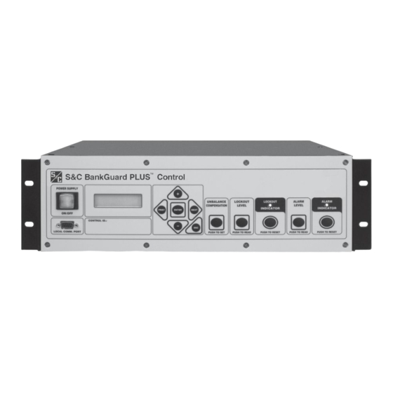
S&C BankGuard PLUS™ Control
TABLE OF CONTENTS
Section
Qualified Persons . . . . . . . . . . . . . . . . . . . . . . . . . . . . . . . 2
Read this Instruction Sheet . . . . . . . . . . . . . . . . . . . . . . . 2
Retain this Instruction Sheet. . . . . . . . . . . . . . . . . . . . . . 2
Warranty . . . . . . . . . . . . . . . . . . . . . . . . . . . . . . . . . . . . . . 2
Latest Document Release . . . . . . . . . . . . . . . . . . . . . . . . 2
Understanding Safety-Alert Messages . . . . . . . . . . . . . . 3
Following Safety Instructions . . . . . . . . . . . . . . . . . . . . . 3
Replacement Instructions and Labels . . . . . . . . . . . . . . 3
Applicable Software . . . . . . . . . . . . . . . . . . . . . . . . . . . . . 5
Ungrounded Wye Banks . . . . . . . . . . . . . . . . . . . . . . . . . 5
Graphical Method . . . . . . . . . . . . . . . . . . . . . . . . . . . . . . . 5
Formula Method . . . . . . . . . . . . . . . . . . . . . . . . . . . . . . . . 9
Gross Overvoltage . . . . . . . . . . . . . . . . . . . . . . . . . . . . . 11
Unbalance Compensation . . . . . . . . . . . . . . . . . . . . . . . 12
Graphical Method . . . . . . . . . . . . . . . . . . . . . . . . . . . . . . 16
Formula Method . . . . . . . . . . . . . . . . . . . . . . . . . . . . . . . 19
Gross Overvoltage . . . . . . . . . . . . . . . . . . . . . . . . . . . . . 21
Alarm Level . . . . . . . . . . . . . . . . . . . . . . . . . . . . . . . . . . . 22
Formula Method . . . . . . . . . . . . . . . . . . . . . . . . . . . . . . . 23
Gross Overvoltage . . . . . . . . . . . . . . . . . . . . . . . . . . . . . 23
Unbalance Compensation . . . . . . . . . . . . . . . . . . . . . . . 24
S&C ELECTRIC COMPANY
Specialists in Electric Power Switching and Protection
Setup Instructions
. . . . . . . . . . . . . . . . . . . . . . . . . . 15
Page
Section
Display Mode Shortcut Buttons . . . . . . . . . . . . . . . . . .26
LCD Setup Mode . . . . . . . . . . . . . . . . . . . . . . . . . . . . . . .27
Hardware and Software Requirements . . . . . . . . . . . .29
Install IntelliLINK Software . . . . . . . . . . . . . . . . . . . . . .29
Start IntelliLINK Software . . . . . . . . . . . . . . . . . . . . . . .29
IntelliLINK Screens . . . . . . . . . . . . . . . . . . . . . . . . . . . . .31
IntelliLINK Menu Tree . . . . . . . . . . . . . . . . . . . . . . . . . .32
IntelliLINK Setup. . . . . . . . . . . . . . . . . . . . . . . . . . . . . . .32
Enter Setup Information . . . . . . . . . . . . . . . . . . . . . . . .33
Unbalance Compensation Feature . . . . . . . . . . . . . . . .40
Calculated Lockout Level. . . . . . . . . . . . . . . . . . . . . . . .47
Calculated Alarm Level . . . . . . . . . . . . . . . . . . . . . . . . .48
Normal Operation . . . . . . . . . . . . . . . . . . . . . . . . . . . . . .49
Page
. . . . . . . . . . . . . . . . . . . . .25
Instruction Sheet 1011-530
©
October 22, 2007
2007
Supersedes 1011-530 dated 2-13-06
Advertisement
Table of Contents

Related Manuals for S&C BankGuard PLUS


Summary of Contents for S&C BankGuard PLUS
-
Page 1: Table Of Contents
S&C BankGuard PLUS™ Control Setup Instructions TABLE OF CONTENTS Section Page Section Page USING THE LCD FOR SETUP INTRODUCTION .....25 Display Mode Shortcut Buttons . -
Page 2: Introduction
INTRODUCTION Qualified Persons WARNING The equipment covered by this publication must be installed, operated, and main- tained by qualified persons who are knowledgeable in the installation, operation, and maintenance of overhead electric power distribution equipment along with the asso- ciated hazards. A qualified person is one who is trained and competent in: •... -
Page 3: Safety Information
SAFETY INFORMATION Understanding There are several types of safety-alert messages which may appear throughout this instruction sheet as well as on labels attached to the IntelliTEAM II Interface Module. Safety-Alert Familiarize yourself with these types of messages and the importance of the various Messages signal words, as explained below. - Page 4 1011-530...
-
Page 5: Ungrounded Wye Banks
Ungrounded Wye Banks Applicable This instruction sheet was prepared for use with software UPPD106S. You can find the release date on the Setup disk label. For questions regarding the applicability of infor- Software mation in this instruction sheet to future software releases, please contact S&C. Ungrounded Wye You must establish the settings for each control device installation, using either graphs or formulas. - Page 6 Figure 1. V versus F/P (Ungrounded Wye Capacitor Bank). 1011-530...
- Page 7 Figure 2. V versus F/P (Ungrounded Wye Capacitor Bank) Graphical Method – Example 1 An installation has the following profile: • Highest anticipated continuous system line-to-neutral voltage (V ): 20 kV • Nameplate rating of the capacitor units (V ): 9.96 kV •...
- Page 8 For F = 1, × 1.072 10kV --------------------------------- - 1.076 per unit 9.96kV For F = 2, × 1.16 10kV ------------------------------ - 1.16 per unit 9.96kV For F = 1, enter at 10 on the horizontal scale. Follow this up to the curve for S = 2 (2 series groups per phase).
-
Page 9: Formula Method
to 7 series groups per phase (interpolate between the curves for S = 6 and S = 8). Here, = 0.0043 per unit. Similarly, for F = 2, enter the graph at 16.67 on the horizontal scale. Follow this up to a point corresponding to 7 series groups per phase. - Page 10 For F = 1, ⋅ ⋅ 20000 ------------------------------------------------------- V o (volts) 10714 volts 2 1 ( ) ⋅ ) 10 1 – 10714 -------------- - (per unit) 1.0757 per unit (or 7.57% overvoltage) 9960 For F = 2, ⋅ ⋅ 20000 (volts) -------------------------------------------------------...
-
Page 11: Gross Overvoltage
For F = 1, ⋅ ⋅ 139440 ------------------------------------------------------- (volts) 21544 volts 2 1 ( ) ⋅ ) 12 1 – 21544 -------------- - V o (per unit) 1.0815 per unit (or 8.15% overvoltage) 19920 For F = 2, ⋅ ⋅ 139440 ------------------------------------------------------- (volts) -
Page 12: Unbalance Compensation
Therefore, the desired gross overvoltage lockout level is: 769 volts 5000 volts ----------------------------------------------------- - 2885 volts For Example 2 above, the V for the critical step (F = 2) was 1303 volts. The V result- ing from shorting out a series group is: ------------------- - 139440 volts 7339 volts 3 7 ( ) 2... - Page 13 ⎛ ⎞ ⎛ ⎞ Per-unit System ⎜ ⎟ ⎜ ⎟ ⎜ ⎟ ⎜ ⎟ System Voltage Line-to-Neutral ⎜ ⎟ ⎜ ⎟ Error Voltage ⎝ Imbalance ⎠ ⎝ Voltage ⎠ from System Voltage ----------------------------------------------------------------------------------------------- - Imbalance Unbalance Compensation – Example 1 Assume a per-unit capacitor bank imbalance of 0.01 and a per-unit system voltage imbalance of 0.005.
- Page 14 Field Determination of the need for Unbalance Compensation. Close the capacitor bank switching device to energize the capacitor bank. Verify that no capacitor units have been isolated from the capacitor bank (check for blown fuses). The LCD should display a voltage that is essentially zero, or at most 50% of the capaci- tor bank neutral-to-ground voltage calculated to result from the isolation of one capaci- tor unit.
-
Page 15: Grounded Wye Banks
Grounded Wye Banks You must establish the settings for each control device installation, using either graphs or formulas. Both methods are described in this section for grounded wye-connected shunt capacitor banks only. It also describes how to calculate the gross overvoltage and alarm levels, and how to coordinate capacitor bank isolation with the individual capacitor unit fuses. -
Page 16: Graphical Method
Graphical Method Figure 3 shows the per-unit voltage applied to surviving capacitor units in a series group (V ), versus the percentage of capacitor units isolated from the same series group (F/P). shows the tap-point voltage percent imbalance (U ), versus the percent- age of capacitor units isolated from the same series group (F/P). - Page 17 Graphical Method – Example 1 An installation has the following profile: • Highest anticipated continuous system line-to-neutral voltage (V ): 20 kV • Nameplate rating of the capacitor units (V ): 9.96 kV • Number of series groups per phase (S): 2 •...
- Page 18 × 1.11 10kV ------------------------------ - 1.114 per unit 9.96kV For F = 1, enter at 10 on the horizontal scale. Follow this up to the curve for S = 2 (2 series groups per phase). Here, U = 5.2%. Similarly, for F = 2, enter the graph at 20 on the horizontal scale. Follow this up to the curve for S = 2.
-
Page 19: Formula Method
between the higher value of U for F = 1 and the lower value of U for F = 2 (= F 1.7% 2.8% ------------------------------- - 2.25% Thus, the desired lockout level for this capacitor bank is 2.25%. Formula Method To calculate the lockout level for the capacitor bank: A. - Page 20 ⋅ 20000 ------------------------------- - (volts) 11111 volts 2 10 2 – 11111 V o (per unit) -------------- - 1.1156 per unit (or 11.56% overvoltage) 9960 Because we are looking for a V of 1.1 or less per unit, our F in this example is 2.
-
Page 21: Gross Overvoltage
For F = 1, ⋅ ------------------------------- - 1.28% 7 12 1 – For F = 2, ⋅ ------------------------------- - U tp 2.78% 7 12 2 – Because the number of series groups per phase in this example is odd, you must com- pute alternate values of U using the adjustment factor for isolation of capacitor units in a series group between the tap point and ground. -
Page 22: Alarm Level
from shorting out a series group is: ----------- - 16.67% – Therefore, the desired gross overvoltage lockout level is: 3.70% 16.67% ---------------------------------------- - 10.19% Alarm Level The alarm lets you choose a voltage level below lockout. When an alarm becomes active, you can choose whether to continue operating the bank (deferring replacement of the failed unit until a convenient time) or to replace the failed unit sooner (minimiz- ing the time that the surviving capacitor units are exposed to overvoltage and thus... -
Page 23: Ungrounded Wye Shunt Reactors
Ungrounded Wye Shunt Reactors You must establish the settings for each control device installation. The method described in this section is for ungrounded wye-connected shunt reactors only. It also describes how to calculate the gross overvoltage level and when to use unbalance com- pensation. -
Page 24: Unbalance Compensation
In the example above, the V was 120 volts. The V resulting from a fault which would open an entire phase winding is: ) volts -- - 7200 3600 volts Therefore, the desired gross overvoltage lockout level is: 3600 volts 120 volts ----------------------------------------------------- - 1860 volts... -
Page 25: Using The Lcd For Setup
Using the LCD for Setup The BankGuard PLUS Automatic Control Device includes a 2-line LCD that gives you access to information about the control device and the capacitor bank/reactor. Table 1 gives you an overview of all of the faceplate buttons used to set up the control device from the LCD. -
Page 26: Display Mode Shortcut Buttons
Button Description When the control device is in display mode and the display is blinking, press this button to cancel a setpoint change. The LCD then shows the original, unchanged value. If the display is not blinking, pressing this button returns the LCD to [N-G Voltage]. -
Page 27: Lcd Setup Mode
UNBALANCE COMPENSATION Button LOCKOUT LEVEL Button ALARM LEVEL Button Unbalance “Lockout Level” “Alarm Level” setpoint compensation value setpoint in use A new calculated “Lockout Time Delay” “Alarm Time Delay” unbalance setpoint setpoint compensation value Comparison between Comparison between the “Lockout Level” the “Alarm Level”... - Page 28 Description Present neutral-to-ground voltage [N-G Voltage] Password, if required [Password] Unbalance compensation value in use [UBC In Use] “Lockout Level” setpoint [Lckout Lvl] “Lockout Time Delay” setpoint [Lockout Delay] “Alarm Level” setpoint [Alarm Level] “Alarm Time Delay” setpoint [Alarm Delay] “Gross Overvoltage Level”...
-
Page 29: Hardware And Software Requirements
Start IntelliLINK The steps below explain how to start the IntelliLINK software when you want to work with the setpoints or stored data in the BankGuard PLUS control device. If you want to Software edit a snapshot (virtual memory file) or simply view the software without data, see Using Snapshots (VM Files) in the Operations Instruction Sheet 1011-540. - Page 30 “live” data that is in the control device, load settings into the control device, and perform maintenance and troubleshooting. Figure 5. Operation Screen for the BankGuard PLUS IntelliLINK Software. NOTE: If the IntelliLINK software does NOT establish communications with a function- ing control device, it displays the following dialog box.
-
Page 31: Intellilink Screens
NOTE: The exact appearance and content of the IntelliLINK screens depend on which version of the software is installed. The screen arrangements shown below apply to all IntelliLINK versions for the BankGuard PLUS control devices (except where noted). To Change Data Values on IntelliLINK Screens... -
Page 32: Intellilink Menu Tree
BankGuard PLUS – standard version IntelliLINK Menu Tree Operation Setup (2 pages) Product Information Communications Communications Setup (2 pages) Communications Troubleshooting (DNP version) Unbalance Setup IntelliLINK Setup To set up the control device for normal operation, you must: Connect your portable computer to the control device and start the IntelliLINK software as described in Start IntelliLINK Software on page 29. -
Page 33: Enter Setup Information
Enter Setup Once communication is established between the IntelliLINK software and the control device, the Operation screen opens. You can now enter the setup information for this Information control device. There are two ways to do this: • Follow the steps in this section to enter all the required values for this control device, beginning at Step 1 below. - Page 34 Unbalance Compensation This setpoint enables or disables unbalance compensation. The choice of values dis- played by this setpoint is dependent on the Installation Type setpoint value. There- fore, the Installation Type setpoint must be set to the correct value before setting the Unbalance Compensation Setpoint.
- Page 35 The range is: 1 to 30 seconds, and latched. The default value is “Latched”. Alarm Contacts Configuration The BankGuard PLUS has two sets of normally open and normally closed (a & b) con- tacts called Alarm and 2nd Alarm. Alarm contacts change state when control power is applied to the BankGuard PLUS, and when control power is off all alarm contacts are in the active state.
- Page 36 When either of these two setpoints is selected all Alarm and 2nd Alarm contacts indi- cate simultaneously for neutral over-voltage or relay trouble. To determine which con- dition caused the alarm the user must connect to the BankGuard PLUS device with their PC using IntelliLINK Setup Software and review the event logs.
- Page 37 Separate Alarm Contacts (new default) Contacts Terminals Power Is At Power-Up At Power-Up No Over-Voltage Over-Voltage Present Present TB1-2&3 Open State at last power-down. Open; closed by reset * Over-voltage If open; closed by reset. Alarm TB1-4&5 Closed State at last power-down. Closed;...
- Page 38 Alarmed at Power-Up With Dual (Redundant) Contacts Contacts Terminals Power Is At Power-Up At Power-Up No Over-Voltage Over-Voltage Present Present TB1-2&3 Alarm Open Open; closed by reset Open; closed by reset * TB1-4&5 Alarm Closed Closed; opened by reset Closed; opened by reset * TB1-7&8 2nd Open Open;...
- Page 39 Figure 8. Setup Screen Page 2. Converts UP Volts to Percent The default for the Control is all related setpoints and the neutral to ground voltage is displayed in Volts. Setting this setpoint value to “Yes” will convert these voltages to a percentage.
-
Page 40: Unbalance Compensation Feature
Location Enter your company’s standard location identification information. This information may help identify the control device to the SCADA master station operator and appears on all reports generated from the control device. You can enter up to 100 characters. Unbalance The Unbalance Compensation (UBC) feature compensates for variances Compensation which result in an error voltage existing between the capacitor bank neutral... - Page 41 Installation Unbalance Potential Device Configu- Unbalance Compensa- Type Compensation ration tion Provided Type Ungnd Wye Reactor Only One neutral-point-to-ground Provides approximate unbal- Reactor 15-Volt-Ampere Potential anced compensation for Device and one line 30-Volt- inherent reactor bank unbal- Ampere Potential Device. ance.
- Page 42 Press the ENTER button to accept the new “InstallType” setpoint value. Using the NEXT button, scroll the LCD to the “Unbal. Comp.” display. Press the ENTER button and Line 2 of the LCD will blink to indicate that the setpoint will accept a new value.
- Page 43 2. Click the Comm button to display Page 1 of the Communications Setup screen (Figure 9). Enter all required information (as described below). Go to the next step. Figure 9. Page 1 of the Communications Setup Screen (DNP Version). This screen includes the following fields: Communications RTU Address If this control device will be accessed via SCADA communications, enter the network address for this installation.
- Page 44 Number of Confirmation Attempts This is the number of times the control device asks for a confirmation when the Appli- cation Layer Confirmations setpoint is enabled. This number includes the initial response transmission. Time Delay Between Attempts If the control device did not receive a confirmation within this time period, it retrans- mits the response with a request for another confirmation, unless the Number of Con- firmation Attempts has been reached.
- Page 45 3. At Page 1 of the Communications Setup screen, click the PgDn button to display Page 2 of the Communications Setup screen (Figure 10). Enter all required information (as described below). Figure 10. Page 2 of the Communications Setup Screen (DNP Version). This screen includes the following fields: SCADA Communication Baud Rate, Port A SCADA Communication Baud Rate, Port B...
- Page 46 • SCADA – This port is connected to a SCADA master station. • Direct – This port is connected directly to another control device and is intended to relay messages to it. RTS Active Before Xmit Duration, Port A RTS Active Before Xmit Duration, Port B This is the amount of time (in milliseconds) that RTS (“request to send”) is active for this port before a transmission takes place.
-
Page 47: Calculated Lockout Level
Verify the Calculated Lockout Level (capacitor banks only) Calculated Lockout Level 1. Check that no capacitor units have been isolated from the bank. 2. De-energize the capacitor bank. Open the capacitor bank switching device. Then ground the bank, observing estab- lished operating procedures and safety precautions. -
Page 48: Calculated Alarm Level
Verify the Calculated Alarm Level (capacitor banks only – optional) Calculated Alarm Level 1. Check that no capacitor units have been isolated from the bank. 2. De-energize the capacitor bank. Open the capacitor bank switching device. Then ground the bank, observing estab- lished operating procedures and safety precautions. -
Page 49: Normal Operation
Do one of the following: • Set the alarm level to a value lower than the lowest voltage just measured. Note that this means that an alarm may occur with fewer capacitor units removed from service. • Set up the unbalance compensation feature, as described in Unbalance Compensa- tion on page 12. - Page 50 1011-530...
Need help?
Do you have a question about the BankGuard PLUS and is the answer not in the manual?
Questions and answers