S&C BankGuard Plus Operation
Hide thumbs
Also See for BankGuard Plus:
- Setup instructions (50 pages) ,
- Operation instructions manual (28 pages) ,
- Installation manual (24 pages)
Table of Contents
Advertisement
Quick Links
BankGuard Plus
Control
®
Table of Contents
Section
Qualified Persons . . . . . . . . . . . . . . . . . . . . . . . . . . . 2
Read this Instruction Sheet . . . . . . . . . . . . . . . . . . . 2
Retain this Instruction Sheet . . . . . . . . . . . . . . . . . . . 2
Proper Application . . . . . . . . . . . . . . . . . . . . . . . . . . 2
Warranty . . . . . . . . . . . . . . . . . . . . . . . . . . . . . . . . . . 2
Understanding Safety-Alert Messages . . . . . . . . . . . 3
Following Safety Instructions . . . . . . . . . . . . . . . . . . 3
Replacement Instructions and Labels . . . . . . . . . . . 3
. . . . . . . . . . . . . . . . . . . . . . . . . 4
Applicable Software . . . . . . . . . . . . . . . . . . . . . . . . . 5
Hardware and Faceplate . . . . . . . . . . . . . . . . . . . . . 5
Control Software . . . . . . . . . . . . . . . . . . . . . . . . . . . . 6
SCADA Communication Equipment . . . . . . . . . . . . . 6
Overvoltage Protection for Capacitor Banks . . . . . . 7
Protection for Reactors . . . . . . . . . . . . . . . . . . . . . . . 7
Automatic Control Features . . . . . . . . . . . . . . . . . . . 8
Capacitor Banks . . . . . . . . . . . . . . . . . . . . . . . . . . 9
Ungrounded Wye Shunt Reactors . . . . . . . . . . . . . .11
Signal Processing . . . . . . . . . . . . . . . . . . . . . . . . . . .12
April 27, 2020
© S&C Electric Company 2003-2020, all rights reserved
Operation
Page
Section
Saving the Setup Configuration . . . . . . . . . . . . . . . .16
Loading a Saved Configuration . . . . . . . . . . . . . . . .16
Viewing (Connect To) a Snapshot . . . . . . . . . . . . . .18
Saving Changes Made to the Snapshot . . . . . . . . . .18
Generating a Report from a Snapshot . . . . . . . . . . .18
Creating a CFG File From a Snapshot . . . . . . . . . . .18
. . . . . . . . . . . . . . . . . . . . . . . . .15
®
. . . . . . . . . . . . . . . . . . . . . .17
. . . . . . . . . . . . . . . . . .19
Instruction Sheet 1011-540
Page
Advertisement
Table of Contents

Related Manuals for S&C BankGuard Plus


Summary of Contents for S&C BankGuard Plus
-
Page 1: Table Of Contents
BankGuard Plus Control ® Operation Table of Contents Section Page Section Page Introduction Generating Reports . . . . . . . . . . . . . . . . . . . . . . . . .15 Qualified Persons . -
Page 2: Introduction
3 and 4 . The latest version of this publication is available online in PDF format at sandc.com/en/support/product-literature/ . Retain this This instruction sheet is a permanent part of your BankGuard Plus Control. Designate a location where you can easily retrieve and refer to this publication. Instruction Sheet... -
Page 3: Safety Information
Safety Information Understanding Several types of safety-alert messages may appear throughout this instruction sheet and on labels and tags attached to the BankGuard Plus Control. Familiarize yourself with Safety-Alert these types of messages and the importance of these various signal words:... -
Page 4: Safety Precautions
Safety Precautions DANGER The BankGuard Plus Control line voltage input range is 93 to 276 Vac. Failure to observe the precautions below will result in serious personal injury or death. Some of these precautions may differ from your company’s operating procedures and rules . -
Page 5: Control Hardware And Software
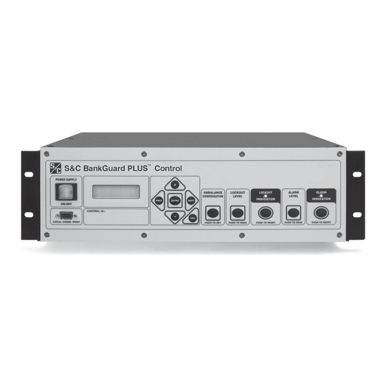
Their configuration is shown in Instruction Sheet 1011-510, “S&C BankGuard Plus® Control: Installation.” Terminal strips (on back) Power supply ON/OFF button Faceplate Local Faceplate LCD Communications and keypad port Figure 1. The location of BankGuard Plus Control components. S&C Instruction Sheet 1011-540... -
Page 6: Control Software
Control Hardware and Software Control Software IntelliLink Setup Software IntelliLink Setup Software is supplied on the Setup disk S&C controls are entirely software-driven. Each control and runs on IBM/PC-compatible computers. This software is shipped with control software and IntelliLink® Setup enables onsite communications with the control software. -
Page 7: Control Operation
18-1992, “IEEE Standard for Shunt Power Capacitors.” The initiated by the BankGuard Plus Control. The control also standard specifies a curve that indicates the permissible will isolate and lock out the entire shunt reactor when a capacitor unit operating time at varying per-unit multiples predetermined neutral-to-ground voltage is exceeded. -
Page 8: Automatic Control Features
Bank/Reactor Lockout and Alarm switch-operator auxiliary switch. This digital input pre- vents nuisance operation of the BankGuard Plus Control The Lockout logic includes a user-selectable time delay Alarm or Lockout functions resulting from neutral-to- (0.2 to 30 second). -
Page 9: Ungrounded And Grounded Wye Shunt
Figure 3. A system diagram of a BankGuard Plus Control for ungrounded wye-connected capacitor banks. Figure 4. A system diagram of a BankGuard Plus Control for grounded wye-connected capacitor banks. S&C Instruction Sheet 1011-540... - Page 10 Control Operation In addition to the neutral-to-ground potential device, one magnitude exceeds a setpoint value continuously for a 30-Volt-Ampere S&C Potential Device is required to be time greater than the applicable Time Delay setpoint installed on any one of the line phases to obtain a reference value, the appropriate control action is taken.
-
Page 11: Ungrounded Wye Shunt Reactors
Unbalance Alarm Level setpoint value is exceeded. Optional Sensing for Unbalance Compensation function Figure 5. A system diagram of a BankGuard Plus Control for ungrounded wye-connected shunt reactors. S&C Instruction Sheet 1011-540... -
Page 12: Signal Processing
Because the sum is obtained from all the line voltages, Signal Processing compensation for fixed-system imbalances is provided. The BankGuard Plus Control hardware samples the During the set-up of the Unbalance Compensation fea- sensor(s) analog output waveform and then converts ture, a neutral-to-ground voltage magnitude sample, and a the samples to digital values. - Page 13 Control Operation to-ground voltage and the reference line voltage. Using memory during the feature’s setup procedure. When the the Law of Cosines, an approximate correct magnitude is control is operating, the stored corrected magnitude is obtained using the reference angle. See Figure 7 on page 12. subtracted from the real-time neutral-to-ground voltage each 200 milliseconds to obtain a compensated neutral- An approximate corrected magnitude is calculated...
- Page 14 Control Operation For a grounded wye capacitor bank with the Unbalance Compensation feature in Enable mode, the Discrete Fourier Transform algorithm yields the magnitude of the sum of the intermediate tap-point voltages (|V tap sum|) and the value of the phase angle (Aref) between the tap- point voltages sum and the reference line voltage.
-
Page 15: Generating Reports
Connect a portable computer to the control and start the IntelliLink software. For details, see the “To Start the IntelliLink Software” section in Instruction Sheet 1011-530, “BankGuard Plus Control: Setup.” If the com- puter is already connected to the control, this step can be skipped. STEP 2. -
Page 16: Saving And Loading Setup Configurations
IntelliLink software. Saving a Setup Configuration For details, see the “To Start the IntelliLink Software” section in Instruction Sheet 1011-530, Complete the following steps to save a setup configuration: “BankGuard Plus Control: Setup.” If the com- Determine which control contains STEP 1. -
Page 17: Viewing Intellilink Software Without Data
Viewing IntelliLink Software Without Data To view the IntelliLink software screens and Help file without connecting to a control or a snapshot: STEP 1. Start the IntelliLink software on a computer. During startup, click on the Cancel button to STEP 2. close the Connect dialog box. -
Page 18: Using Snapshots (Vm Files)
For details, see the “To Start the IntelliLink For details, see the “Viewing (Connect To) a Software” section in Instruction Sheet 1011-530, Snapshot” section. “BankGuard Plus Control: Setup.” If the com- Change the configuration settings in the STEP 2. puter is already connected to the control, this snapshot as needed. -
Page 19: Updating Control Software
Install the contents of the new Setup disk on the computer. For details, see the “To Start the IntelliLink Software” section in Instruction Sheet 1011-530, “BankGuard Plus Control: Setup.” STEP 2. Connect the computer to the LOCAL COMM PORT or optical port on the control.
Need help?
Do you have a question about the BankGuard Plus and is the answer not in the manual?
Questions and answers