Table of Contents
Advertisement
S&C Vista
Underground Distribution Switchgear
®
Table of Contents
Section
Qualified Persons . . . . . . . . . . . . . . . . . . . . . . . . . . . 2
Read this Instruction Sheet . . . . . . . . . . . . . . . . . . . 2
Video . . . . . . . . . . . . . . . . . . . . . . . . . . . . . . . . . . . . . 2
Retain this Instruction Sheet . . . . . . . . . . . . . . . . . . . 2
Proper Application . . . . . . . . . . . . . . . . . . . . . . . . . . 2
Special Warranty Provisions . . . . . . . . . . . . . . . . . . . 3
Understanding Safety-Alert Messages . . . . . . . . . . . 4
Following Safety Instructions . . . . . . . . . . . . . . . . . . 4
Replacement Instructions and Labels . . . . . . . . . . . 4
Location of Safety Labels . . . . . . . . . . . . . . . . . . . . . 5
. . . . . . . . . . . . . . . . . . . . . . . . . 6
Inspection . . . . . . . . . . . . . . . . . . . . . . . . . . . . . . . . . 7
Packing . . . . . . . . . . . . . . . . . . . . . . . . . . . . . . . . . . . 7
Handling . . . . . . . . . . . . . . . . . . . . . . . . . . . . . . . . . . 7
Time-Current Characteristics and Settings . . . . . . . 8
Trip Mode . . . . . . . . . . . . . . . . . . . . . . . . . . . . . . . . . 9
User Access and Privileges . . . . . . . . . . . . . . . . . . . 9
Hardware and Software . . . . . . . . . . . . . . . . . . . . . .10
Installing the USB Driver . . . . . . . . . . . . . . . . . . . . . .10
. . . . . . . . . . . . . . . . . . . . . . . 11
Connecting to the Overcurrent Control
Connecting to the Overcurrent Control Using
USB . . . . . . . . . . . . . . . . . . . . . . . . . . . . . . . . . . . . .17
Explorer . . . . . . . . . . . . . . . . . . . . . . . . . . . . . . . . .18
Logging in to the Control . . . . . . . . . . . . . . . . . . . . 20
Default Passwords . . . . . . . . . . . . . . . . . . . . . . . . . .21
Changing the Admin Password . . . . . . . . . . . . . . . .21
Changing the User Password . . . . . . . . . . . . . . . . . 23
June 10, 2019
© S&C Electric Company 2018-2019, all rights reserved
Programming
Page
Section
Load Current Menu . . . . . . . . . . . . . . . . . . . . . . . . . 27
Control Settings Menu . . . . . . . . . . . . . . . . . . . . . . 27
About Menu . . . . . . . . . . . . . . . . . . . . . . . . . . . . . . 27
Changing the Admin and User Password . . . . . . . . 28
Changing the Interrupter ID . . . . . . . . . . . . . . . . . . 29
Changing the Global Settings . . . . . . . . . . . . . . . . . 29
USB Network Settings . . . . . . . . . . . . . . . . . . . . . . 33
Trip Mode . . . . . . . . . . . . . . . . . . . . . . . . . . . . . . 34
Programming Interrupter 1 and Interrupter 2 . . . . . 34
Time Overcurrent Phase Protection . . . . . . . . . . . . 38
Ground Protection . . . . . . . . . . . . . . . . . . . . . . . . . . 39
Negative Sequence . . . . . . . . . . . . . . . . . . . . . . . . .41
Sensitive Earth Fault . . . . . . . . . . . . . . . . . . . . . . . . 42
Factory Default Protective Settings . . . . . . . . . . . . 44
Factory Default Reset . . . . . . . . . . . . . . . . . . . . . . . 44
Trip Event Log . . . . . . . . . . . . . . . . . . . . . . . . . . . . . 46
Diagnostic Event Log . . . . . . . . . . . . . . . . . . . . . . . .47
Control Self-Test Report . . . . . . . . . . . . . . . . . . . . . 48
. . . . . . . . . 14
Trip Outputs . . . . . . . . . . . . . . . . . . . . . . . . . . . . . . 53
Signal Inputs . . . . . . . . . . . . . . . . . . . . . . . . . . . . . . 54
Power Inputs . . . . . . . . . . . . . . . . . . . . . . . . . . . . . . 54
Programming the S&C Vista
Overcurrent Control 2.0
. . . . . . . . . . . . . . . . . . . . . . 51
. . . . . . . . . . . . . . . . . . . . . . . . 52
. . . . . . . . . . . . . . . . . . . . . . . . . . . . . 55
. . . . . . . . . . . . . . . . . . . . . . . . 62
Instruction Sheet 681-530
Page
. . . . . . . . . . 25
. . . . . . . . . . . . . . . 56
. . . . . . . . . . 61
Advertisement
Table of Contents

Subscribe to Our Youtube Channel
Related Manuals for S&C Vista


Summary of Contents for S&C Vista
-
Page 1: Table Of Contents
S&C Vista Underground Distribution Switchgear Programming the S&C Vista ® Overcurrent Control 2.0 Programming Table of Contents Section Page Section Page Introduction Understanding the Status Display . . . . . . . . . . 25 Qualified Persons . -
Page 2: Introduction
The video is supplementary to this instruction sheet and should in no way be considered a replacement for the written instructions. Retain this This instruction sheet is a permanent part of the S&C Vista Underground Distribution Switchgear. Designate a location where you can easily retrieve and refer to this publication. Instruction Sheet A copy of these instructions should be stored in the instruction manual holder, if present. -
Page 3: Special Warranty Provisions
Special Warranty The standard warranty contained in seller’s standard conditions of sale, as set forth in Price Sheets 150 and 181, applies to Vista Underground Distribution Switchgear and its Provisions associated options. The Vista Overcurrent Control 2.0 has the following warranty: the... -
Page 4: Safety Information
Center at 1-888-762-1100 or 1-773-338-1000 outside the U.S. NOTICE Read this instruction sheet thoroughly and carefully before installing and programming your S&C Vista Overcurrent Control . Replacement If you need additional copies of this instruction sheet, contact your nearest S&C Sales Office, S&C Authorized Distributor, S&C Headquarters, or S&C Electric Canada Ltd. -
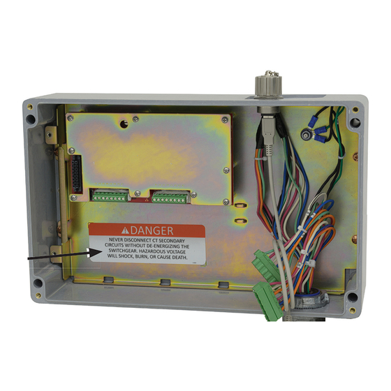
Page 5: Location Of Safety Labels
Safety Information Location of Safety Labels Reorder Information for Safety Information Location Safety Alert Message Description Part Number DANGER Hazardous voltage inside . Will shock, burn, or cause death . . . G-9636 Never disconnect CT secondary circuits without de-energizing the switchgear . DANGER G-9635 Hazardous voltage will shock, burn, or cause death . -
Page 6: Safety Precautions
Some of these precautions may differ from your company’s operating procedures and rules . Where a discrepancy exists, follow your company’s operating procedures and rules . 1 . QUALIFIED PERSONS. Access to the Vista 4 . SAFETY LABELS. Do not remove or obscure any overcurrent control must be restricted only to of the “DANGER,”... -
Page 7: Shipping And Handling
Notify S&C Electric Company in all instances of loss and/or damage. Packing The overcurrent control for your S&C Vista Underground Distribution System is housed in an enclosure mounted on the operation side of the switchgear. For UnderCover™ Style and Wet-Vault Mounted-Style Vista Underground Distribution Switchgear, the enclosure is fully submersible. -
Page 8: Product Overview
Product Overview The overcurrent control is programmed using a personal computer connected to the control via a USB cable. The control features a variety of time-current characteristic (TCC) curves and definite time settings listed in the "Overcurrent Control Settings" section starting on page 56. -
Page 9: Trip Mode
Product Overview Trip Mode Three-phase fault interrupters are designed for three-phase tripping. Single-phase tripping is not possible with three-phase fault interrupters. With single-phase fault interrupters, the overcurrent control can be programmed for either single-phase trip/single-phase lockout or single-phase trip/three-phase lockout. When set for single-phase trip/single-phase lockout the control will trip only the phase experiencing an overcurrent condition. -
Page 10: Computer Requirements
Microsoft Windows to install the incorrect driver . A Vista Overcurrent Control USB driver is required to access and program the control via USB. The latest Vista overcurrent control USB driver software release for your version of Microsoft Windows is posted at http://www.sandc.com/vistaocc. -
Page 11: Removing The Electronics Module For Service Center Programming
NOTICE S&C does not recommend removing the submersible S&C Overcurrent Control used in UnderCover Style and Wet-Vault Mounted Style Vista switchgear from its enclosure for workbench programming . Opening the submersible enclosure may damage the sealing gasket . Contact your local S&C Sales Office or the S&C Global Support and Monitoring Center at 1-888-762-1100 (or 1-773-338-1000 outside the U .S . - Page 12 Removing the Electronics Module for Service Center Programming Loosen the screws holding the two trip connectors in place. Disconnect the trip STEP 2. connectors and USB connector from the front of the electronics module. See Figure 3. Connector Trip Connectors Figure 3.
- Page 13 Removing the Electronics Module for Service Center Programming Grasp the electronics module by the lifting handle and the rear lifting tab, and STEP 4. lift it straight up from the base plate to raise the stand-off attached to the inside of the cover of the electronics module.
-
Page 14: Reinstalling The Electronics Module
The control will power up if suffi cient current is fl owing through the Vista switchgear. See Figure 8 on page 15. Holes Holes... - Page 15 Reinstalling the Electronics Module Screws Screws (not visible) Figure 8. Lower the electronics module onto the base plate and tighten the four captive screws. STEP 3. Tighten the four captive screws that secure the electronics module to the base plate. Start tightening the screws by hand to avoid cross threading. See Figure 8.
- Page 16 Reinstalling the Electronics Module STEP 5. Place the cover on the control enclosure and tighten the captive screws that secure the cover in place. See Figure 10. Enclosure cover Figure 10. Secure the enclosure cover. S&C Instruction Sheet 681-530...
-
Page 17: Usb
Connecting to the Overcurrent Control Connecting to the To connect to the overcurrent control : Overcurrent Control STEP 1. Make sure the USB driver has been installed on the computer per the instructions Using USB in the “Installing the USB Driver” section on page 10. STEP 2. -
Page 18: Accessing The Overcurrent Control With A Web Browser
Accessing the Overcurrent Control with a Web Browser The software for the overcurrent control is resident on the control and can be accessed using a Web browser. (See the “Computer Requirements” section on page 10 for compatible Web browsers and operating systems.) After connecting to the control by connecting to the USB port, access the control by opening the Web browser. - Page 19 Accessing the Overcurrent Control with a Web Browser From the Compatibility View Settings menu, uncheck the box next to “Display STEP 2. intranet sites in Compatibility View.” See Figure 13. Figure 13. Uncheck “Display intranet sites in Compatibility View” from the Compatibility View Settings menu.
-
Page 20: Logging In To The Control
This will open the Login screen. See Figure 14. There are three types of login: Figure 14. The Vista Overcurrent Control Login screen. • admin – The admin login should ONLY be used when initially setting up the control or as directed by S&C, such as for installing a fi rmware update. -
Page 21: Logging In For The First Time
Logging In for the First Time Default Passwords NOTICE DO NOT lose the admin password . For security reasons, there is no password- retrieval system built in to the overcurrent control . If the admin password is lost, the control must be returned to S&C Electric Company to restore access to the control . The overcurrent control comes with two default passwords, one for the “admin”... - Page 22 Logging In for the First Time STEP 2. Click on the Control Settings tab on the side menu. Then navigate to the “Change Admin Password” section of the Control Settings screen. See Figure 16. Control Settings Figure 16. The Change Admin Password menu. STEP 3.
-
Page 23: Changing The User Password
Logging In for the First Time Changing the User To change the User password: Password STEP 1. At the Login screen, enter the user username and password. See Figure 19. Figure 19. Enter the username and password. When logging in with the user login for the first time, a prompt to change the password will open in the Control Settings menu. - Page 24 Logging In for the First Time STEP 3. If desired, click on the Eye icon to on the right side of the Current Password fi eld to reveal the text of the password. See Figure 21. Eye icon Figure 21. Click on the Eye icon to reveal the password. STEP 4.
-
Page 25: Understanding The Status Display
Understanding the Status Display The Status screen and menus provide a summary of the status of the overcurrent control, measurement of the load current of the associated fault interrupters, and the control settings. It also provides a summary of the login status, the overcurrent control serial number and MAC address, and the fi rmware installed on the control. -
Page 26: Status Display "Black Box
Understanding the Status Display Status Display “Black The FAULT INTERRUPTER 1 and FAULT INTERRUPTER 2 orange LED displays indicate whether a fault interrupter has experienced a Trip event initiated by the overcurrent Box” control. If more than one fault interrupter has responded to a fault, both LED displays light. -
Page 27: Load Current Menu
Understanding the Status Display Load Current Menu The Load Current menu shows a snapshot of the load current going through the two fault interrupters or through ground. When the control is removed from its enclosure for service center programming, the load current will be zero in all interrupting ways and to ground. -
Page 28: Programming The Control Settings
• Change the User and Admin passwords from their factory default settings • Confi rm the system frequency (60 Hz is the default setting) • Confi rm the continuous current rating matches the ratings of the Vista switchgear, as listed on the nameplate •... -
Page 29: Changing The Interrupter Id
Click on the Save button. A message that the setting has been saved will display. Changing the Global The global settings are programmed at the factory to match the Vista switchgear model. Recheck all settings to make sure they are accurate before energizing the switchgear. If... - Page 30 Programming the Control Settings Nominal Frequency The Nominal Frequency setting confi gures the overcurrent control for the operating frequency of the switchgear. To change the switchgear frequency: STEP 1. From the Global Settings menu, select the frequency setting to match the system operating frequency.
- Page 31 Programming the Control Settings Interrupter Rating NOTICE Make sure to select the correct interrupting rating for the switchgear . These ratings will set the upper limit of the Definite Time Current, Low-Current Cutoff, and Minimum Trip Current values . The Interrupter Rating setting confi gures the overcurrent control for the interrupting rating of the switchgear.
- Page 32 The Trip Mode setting confi gures the interrupting setting for the available interrupting ways (Interrupter 1 and Interrupter 2) of the overcurrent control. There are three trip modes available for Vista Underground Distribution Switchgear: • Single-Phase Trip/Single-Phase Lockout • Single-Phase Trip/Three-Phase Lockout •...
-
Page 33: Usb Network Settings
Programming the Control Settings USB Network Settings The USB network settings are not user-editable. Refer to the “Installing the USB Driver” section on page 10 for information on installing the USB driver. The factory default USB settings are: USB Network Settings MAC Address xx:xx:xx:xx:xx:xx (Set at Factory) -
Page 34: Programming The Overcurrent Protection Settings
Trip event. Ground Protection, Negative Sequence, and Sensitive Earth Fault protection settings are available for switchgear in this Trip Mode setting. Single- Phase Trip/Three-Phase Lockout mode is only available on 12.5-kA and 16-kA Vista switchgear models. Three-Phase Trip/Three-Phase Lockout An interrupting way in Three-Phase Trip/Three-Phase Lockout mode is equipped with three-pole fault interrupters. - Page 35 Programming the Overcurrent Protection Settings Figure 30. The Time Overcurrent Phase Protection menu, single-phase trip/single-phase lockout. Figure 31. The Time Overcurrent Phase Protection menu, three-phase trip/three-phase lockout. S&C Instruction Sheet 681-530...
- Page 36 Programming the Overcurrent Protection Settings Different TCC families have different setting selections and editable fi elds. Fields that are not editable will be grey. Selections that are invalid will prompt an error message, and any cell with an invalid value will be highlighted in yellow after clicking on the Save button.
- Page 37 Programming the Overcurrent Protection Settings If the coordination settings selections are invalid, or contradictory, an error message explaining the problem will appear, and any cell with an invalid value will be highlighted in yellow after clicking on the Save button. Please note that selections will not be saved until the error is fixed.
-
Page 38: Overcurrent Protection Setting Definitions
Definite Time selection is available if a IEC, IEEE, or Vista coordination phase TCC curve is selected or if no TCC curve is specified for phase protection. Definite-Time Phase Protection settings will trip the fault interrupter if the selected current exceeds the setting value for the specified time setting. -
Page 39: Ground Protection
Inverse Curve or Definite Time settings. Curve Family – Select the TCC Curve Family: IEC, IEEE, or Vista Coordination curve. For more details on the curve families, see the “Overcurrent Control Settings” section on page 56 for the curve families available. - Page 40 Definite Time selection is available if a IEC, IEEE, or Vista coordination phase TCC curve is selected or if no TCC curve is specified for phase protection. Definite-Time Phase Protection settings will trip the fault interrupter if the selected current exceeds the setting value for the specified time setting.
-
Page 41: Negative Sequence
Inverse Curve or the Definite Time settings. Curve Family – Select the TCC curve family: IEC, IEEE, or Vista Coordination. For more details on the curve families, see the “Overcurrent Control Settings” section on page 56 for the curve families available. -
Page 42: Sensitive Earth Fault
Definite Time selection is available if a IEC, IEEE, or Vista coordination phase TCC curve is selected or if no TCC curve is specified for phase protection. Definite-Time Phase Protection settings will trip the fault interrupter if the selected current exceeds the setting value for the specified time setting. - Page 43 Definite Time selection is available if a IEC, IEEE, or Vista coordination phase TCC curve is selected or if no TCC curve is specified for phase protection. Definite-Time Phase Protection settings will trip the fault interrupter if the selected current exceeds the setting value for the specified time setting.
-
Page 44: Factory Defaults And Factory Default Reset
Time Overcurrent Phase Protection Element Protection Element ENABLED ENABLED ENABLED DISABLED DISABLED DISABLED Curve Family Vista Speed Vista Speed Vista Speed Vista Coord . Vista Coord . Vista Coord . Inverse Segment Ampere Rating 200E 200E 200E Minimum-Trip Current, A Time Multiplier 1 .00... - Page 45 “Changing the Global Settings” section on page 29. STEP 3. Update the Interrupter IDs to match the way designations on the Vista switchgear, or change to the user's preferred naming convention. STEP 4. Reprogram the Overcurrent Protection Settings as explained in the “Programming the Overcurrent Protection Settings”...
-
Page 46: Viewing Event Logs
Viewing Event Logs Trip Event Log The Trip Event Log displays the last 64 events recorded by the overcurrent control. The Trip Event Log records seven messages in the order the event occurs, with the most recent event on top. Trip events remain recorded even if the control loses power and will only be removed if more than 64 events are recorded (the oldest event will be overwritten) or if the log is cleared manually. -
Page 47: Diagnostic Event Log
Viewing Event Logs Diagnostic Event Log The Diagnostic Event Log records event messages in a fi rst-in-fi rst out basis with the most recent events on top. Diagnostic events will remain recorded even if the control loses power and will only be removed if more than 12 events are recorded (the oldest event will be overwritten) or if the log is cleared manually. -
Page 48: Control Self-Test Report
Viewing Event Logs Event Category Legend: OK = Operating within normal parameters ERROR = Operating outside of normal parameters (The control requires immediate servicing. Contact the local S&C Sales Office.) TRIP = Shows the Magnetic Latching Solenoid (MLS) voltage upon trip POWERUP = Shows when the overcurrent control was powered on The overcurrent control tests vital subsystems at power up and periodically thereafter to ensure the control is working properly. - Page 49 Viewing Event Logs Figure 40. A Control Self-Test Report. NOTICE If a control error is registered on the Control Self-Test report, notify S&C Electric Company . A control in an error state may not operate as expected . S&C Instruction Sheet 681-530...
- Page 50 Viewing Event Logs Table 7. Control Self-Test Report Description Self-Test Item Description Elapsed Time Counter The amount of time the control has been powered . MLS Voltage- Interrupter1 - A Phase Magnetic Latching Solenoid (MLS) trip capacitor voltage MLS Voltage- Interrupter2 - A Phase MLS Voltage- Interrupter1 - B Phase MLS Voltage- Interrupter2 - B Phase MLS Voltage- Interrupter1 - C Phase...
-
Page 51: Performing A Trip Test
Trip Mode: Single-Phase, Interrupter 2, Phase A Trip Mode: Single-Phase, Interrupter 2, Phase B Trip Mode: Single-Phase, Interrupter 2, Phase C To test trip the Vista Underground Distribution Switchgear: STEP 1. Click on the Test Trip tab and select the Test Trip menu. From the drop-down menu, select the Trip mode desired for the switchgear confi guration. -
Page 52: Updating Firmware
To update the overcurrent control fi rmware: STEP 1. Log in to the S&C Automation Customer Support Portal and open the “Vista Overcurrent Control” workspace. Download the latest fi rmware fi le, as directed by S&C Electric Company, and move it from the Downloads folder to the desktop. -
Page 53: External Connections
External Connections Trip Outputs This section describes each of the external connections to the control. Included in the following tables are terminal numbers, terminal names, and mating-connector part numbers (where applicable.) Terminal numbers are identifi ed by labels on the electronics module or terminal block. -
Page 54: Signal Inputs
External Connections Signal Inputs Signal inputs Power inputs Figure 44. Signal and power inputs. Table 9. Signal Inputs Terminal Number Signal Pole Fault Interrupter 1, Phase A Fault Interrupter 1, Phase B Fault Interrupter 1, Phase C Fault Interrupter 1, Residual Fault Interrupter 2, Phase A Fault Interrupter 2, Phase B Fault Interrupter 2, Phase C... -
Page 55: Specifications
Specifications Table 11. Specifications USB Power Type A to Type A USB cable 2 .5 W 14 A RMS in all three phases, or 42 A RMS in a 600-A models single phase 28 A RMS in all three phases, or 84 A RMS in a CT Power 900-A models single phase . -
Page 56: Overcurrent Control Settings
Overcurrent Control Settings The Vista Overcurrent Control can be programmed to provide a wide variety of settings combinations. Listed below are the setting ranges that are available to the overcurrent control. Table 12. IEC Curves Time Overcurrent Phase Protection Inverse Segment... - Page 57 Overcurrent Control Settings Table 13. IEEE Curves Time Overcurrent Phase Protection Standard Inverse (U1) Very Inverse (U2) Extremely Inverse (U3) Inverse Segment Long-Time Inverse (U4) Short-Time Inverse (U5) Continuous Current 900/1200 Short Circuit, RMS Sym. Short Circuit, RMS Sym. 12.5 and 16 kA 25 kA 12.5 and 16 kA 25 kA...
- Page 58 Overcurrent Control Settings Table 14. Vista Speed - E Speed Curves Time Overcurrent Phase Protection Inverse Segment Continuous Current 900/1200 7E, 10E, 13E, 15E, 20E, 25E, 30E, 15E, 20E, 25E, 30E, 40E, 50E, 65E, 40E, 50E, 65E, 80E, 100E, 125E,...
- Page 59 Overcurrent Control Settings Table 17. Vista Coordination - Tap Time Overcurrent Phase Protection Inverse Segment 900/1200 Ampere Rating 15, 20, 25, 30, 40, 50, 65, 80, 100, 30, 40, 50, 65, 80, 100, 150, 200, 250, 150, 200, 250, 300, 350, 400...
- Page 60 Overcurrent Control Settings Table 18. Vista Coordination - Main Time Overcurrent Phase Protection Inverse Segment Main 900/1200 25, 30, 40, 50, 65, 80, 100, 150, 200, Ampere Rating 30, 40, 50, 65, 80, 100, 150, 200, 250, 250, 300, 350, 400, 450, 500, 600,...
-
Page 61: Thermal Characteristic Protection
Thermal Characteristic Protection One final consideration in the selection of ANSI/US and IEC curve families to achieve proper power system coordination is the Thermal Characteristic Protection of the Vista Overcurrent Control. The control will self-protect its internal power supply and current-... -
Page 62: Warning Messages
. the switchgear according to cause unplanned loss of the Trip mode selected . There WARNING load . is no provision to test Vista Underground Distribution Switchgear without operating the switchgear . S&C Instruction Sheet 681-530...
Need help?
Do you have a question about the Vista and is the answer not in the manual?
Questions and answers