S&C BankGuard Plus Installation Manual
Hide thumbs
Also See for BankGuard Plus:
- Setup instructions (50 pages) ,
- Operation instructions manual (28 pages) ,
- Operation (19 pages)
Table of Contents
Advertisement
Quick Links
S&C BankGuard Plus
Table of Contents
Section
Qualified Persons . . . . . . . . . . . . . . . . . . . . . . . . 2
Read this Instruction Sheet . . . . . . . . . . . . . . . . . 2
Retain this Instruction Sheet . . . . . . . . . . . . . . . . 2
Warranty. . . . . . . . . . . . . . . . . . . . . . . . . . . . . . . . 2
Understanding Safety-Alert Messages . . . . . . . . 3
Following Safety Instructions . . . . . . . . . . . . . . . . 3
Replacement Instructions . . . . . . . . . . . . . . . . . . 3
Applicable Software . . . . . . . . . . . . . . . . . . . . . . . 4
Pre-Installation Checklist . . . . . . . . . . . . . . . . . . . 4
In-Shop Setup . . . . . . . . . . . . . . . . . . . . . . . . . . . 4
The latest BankGuard Plus Control Instruction Sheets are posted as PDF files at www.sandc.com >
Support > Product Literature. BankGuard Plus Control software (all revisions) can be downloaded at
www.sandc.com > Support > S&C Automation Customer Support Portal. If you need assistance, please
contact customerportal@sandc.com or phone (800) 621-5546.
December 5, 2011 © S&C Electric Company
®
Control
Installation
Page
NOTICE
Section
Installation . . . . . . . . . . . . . . . . . . . . . . . . . . . . . . 5
Test the Control . . . . . . . . . . . . . . . . . . . . . . . . . 10
Installation . . . . . . . . . . . . . . . . . . . . . . . . . . . . . .11
Test the Control . . . . . . . . . . . . . . . . . . . . . . . . . 13
Installation . . . . . . . . . . . . . . . . . . . . . . . . . . . . . 14
Test the Control . . . . . . . . . . . . . . . . . . . . . . . . . 17
Communication Equipment. . . . . . . . . . . . . . . . . 18
Installation and Connection Drawings . . . . . . . . . 19
Instruction Sheet 1011-510
Page
Advertisement
Table of Contents

Related Manuals for S&C BankGuard Plus


Summary of Contents for S&C BankGuard Plus
-
Page 1: Table Of Contents
In-Shop Setup ......4 NOTICE The latest BankGuard Plus Control Instruction Sheets are posted as PDF files at www.sandc.com > Support > Product Literature. BankGuard Plus Control software (all revisions) can be downloaded at www.sandc.com >... -
Page 2: Introduction
3. The latest version of this instruction sheet is available online in PDF format at www.sandc.com. Select: Support/Product Literature Library. Retain this Instruction This instruction sheet is a permanent part of your S&C BankGuard Plus. Designate a Sheet location where you can easily retrieve and refer to this publication. -
Page 3: Safety Information
Safety Information Understanding There are several types of safety-alert messages which may appear throughout this Safety-Alert Messages instruction sheet. Familiarize yourself with these types of messages and the impor- tance of the various signal words, as explained below . Ç DANGER “DANGER”... -
Page 4: Installation
S&C Electric Company. Pre-Installation Checklist Before you install the BankGuard Plus Control, carry out the following steps. This is b est done in the shop before you leave for the installatin site. Step 1 Inspect the control device for visible damage. -
Page 5: Ungrounded Wye Banks
Before attempting to access an existing installation, check carefully for visible or audible signs of electrical or physical malfunction (do this before touching or operating the BankGuard Plus Control or any other part of the installation). These warning signs include such things as smoke, fire, open fuses, crackling noises, loud buzzing, etc. - Page 6 Make the connections to the terminal strips on the back of the control device. The BankGuard Plus Control includes numbered terminal strips on the back of the enclosure for external control-wiring connections. See Figure 1, Table 1, and the electrical diagrams at the end of this instruction sheet.
- Page 7 Table 1. Terminal strip contact functions. NOTICE BankGuard Plus relay contacts are rated for: 16A @ 250 Vac, 0.5A @ 125 Vdc, and 16A @ 24 Vdc. Installation of an interposing relay is mandatory if these ratings could be exceeded.
- Page 8 If necessary, connect the potential devices or voltage transformers used for unbalance compensation. If the BankGuard Plus Control uses the optional unbalance compensation feature, you must also connect the output terminals of other voltage monitoring devices: A. To detect and compensate for the inherent capacitor bank imbalance only, in applications where the source is grounded, connect to one of the following: •...
- Page 9 The circuits connecting the potential devices/voltage transformers to the BankGuard Plus Control must be free of variable loads, variable voltage drops, and ground loops. This insures that the monitored voltages accurately represent the magnitude and phase angle of the bus voltages.
-
Page 10: Test The Control
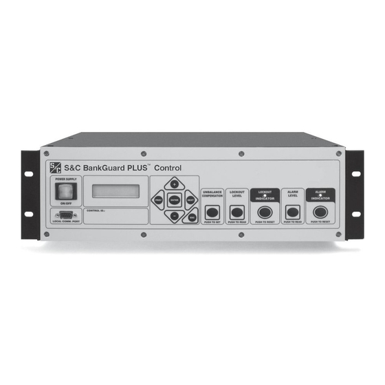
Instruction Sheet 1011-530. The “Field Determination of Need for Unbalance Compen- sation Procedure”, given in Setup Instruction Sheet 1011-530, can also be performed to determine if the Unbalance Compensation feature should be utilized. Figure 2. BankGuard Plus Control faceplate. S&C Instruction Sheet 1011-510... -
Page 11: Grounded Wye Banks
For a grounded wye-connected capacitor bank, the BankGuard Plus control requires three potential devices to monitor intermediate tap point voltages. The intermediate tap point for each phase of the bank should be located as follows: •... - Page 12 Before attempting to access an existing installation, check carefully for visible or audible signs of electrical or physical malfunction (do this before touching or operating the BankGuard Plus Control or any other part of the installation). These warning signs include such things as smoke, fire, open fuses, crackling noises, loud buzzing, etc.
-
Page 13: Test The Control
Grounded Wye Banks • Induced voltages in control wiring. Proper shielding is important. • Ground loops caused by differences in voltage between the grounding points of tap-point potential devices and those of phase-to-ground potential devices. Preferably, the secondaries of all the potential devices should be grounded at one point (per proposed ANSI C57.13.3, “Guide for the Grounding of Instrument Transformer Secondary Circuits and Cases”). -
Page 14: Ungrounded Wye Shunt Reactors
Before attempting to access an existing installation, check carefully for visible or audible signs of electrical or physical malfunction (do this before touching or operating the BankGuard Plus Control or any other part of the installation). These warning signs include such things as smoke, fire, open fuses, crackling noises, loud buzzing, etc. - Page 15 Step 2 Make the connections to the terminal strips on the back of the control. The BankGuard Plus Control includes numbered terminal strips on the back of the enclosure for external control-wiring connections. See Figure 1, Table 1, and the electrical diagrams at the end of this instruction sheet.
- Page 16 Ungrounded Wye Shunt Reactors • Three S&C 30-Volt-Ampere Potential Devices rated for full system volt- age, each connected to a phase of the station bus from which the reactor is tapped. Connect to TB1-9, TB1-10, TB1-11, and TB2-12 (Phase voltage return).
-
Page 17: Test The Control
Ungrounded Wye Shunt Reactors Test the Control At this point, you can test the faceplate LEDs and buttons. See Figure 2 on page 10. A. Press the POWER SUPPLY button. If the control has power, the button will light up (green). If the LOCKOUT INDICATOR or ALARM INDICATOR LED turns ON, press the corresponding RESET button to clear it. -
Page 18: Communication Equipment
When combined with suitable communications equipment and protocols, this permits you to remotely monitor and control the BankGuard Plus installation. S&C Electric Company supports the BankGuard Plus Control with a variety of communi- cations hardware options: • S&C SpeedNet™ Radio •... -
Page 19: Installation And Connection Drawings
Installation and Connection Drawings S&C Instruction Sheet 1011-510... - Page 20 Installation and Connection Drawings S&C Instruction Sheet 1011-510...
- Page 21 Installation and Connection Drawings S&C Instruction Sheet 1011-510...
- Page 22 Installation and Connection Drawings S&C Instruction Sheet 1011-510...
- Page 23 Installation and Connection Drawings S&C Instruction Sheet 1011-510...
Need help?
Do you have a question about the BankGuard Plus and is the answer not in the manual?
Questions and answers