Table of Contents
Advertisement
Quick Links
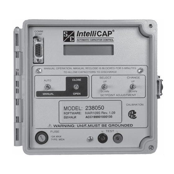
S&C IntelliCap
®
Automatic Capacitor Control
Table of Contents
Section
Qualified Persons . . . . . . . . . . . . . . . . . . . . . . . . . . . . . 2
Read this Instruction Sheet . . . . . . . . . . . . . . . . . . . . . . 2
Retain this Instruction Sheet . . . . . . . . . . . . . . . . . . . . . 2
Proper Application . . . . . . . . . . . . . . . . . . . . . . . . . . . . . 2
Special Warranty Provisions . . . . . . . . . . . . . . . . . . . . . 2
Understanding Safety-Alert Messages . . . . . . . . . . . . . 4
Following Safety Instructions . . . . . . . . . . . . . . . . . . . . . 4
Replacement Instructions and Labels . . . . . . . . . . . . . . 4
. . . . . . . . . . . . . . . . . . . . . . . . . . . . 5
The latest instruction sheets are posted as PDF files at sandc.com/en/support/product-literature/ . IntellCap software
can be downloaded at sandc.com/en/support/sc-customer-portal/ . If you need assistance, please contact GSMC@
sandc.com or call (888) 762-1100 .
December 4, 2017
© S&C Electric Company 2003-2017, all rights reserved
Installation
Page
Section
Installation
Applicable Software . . . . . . . . . . . . . . . . . . . . . . . . . . . . 6
Pre-Installation Checklist . . . . . . . . . . . . . . . . . . . . . . . . 6
Optional In-Shop Setup . . . . . . . . . . . . . . . . . . . . . . . . . 6
Installing the Current Sensor (var only) . . . . . . . . . . . . . 7
Onsite Installation . . . . . . . . . . . . . . . . . . . . . . . . . . . . . . 9
Meter Base Mounting . . . . . . . . . . . . . . . . . . . . . . . . . . 10
Bracket Mounting . . . . . . . . . . . . . . . . . . . . . . . . . . . . . 14
Testing Capacitor Bank Operation . . . . . . . . . . . . . . . . 17
Setting the Control for Manual Operation . . . . . . . . . . 17
Wiring Diagrams . . . . . . . . . . . . . . . . . . . . . . . . . . 18
NOTICE
Instruction Sheet 1022-510
Page
Advertisement
Table of Contents

Related Manuals for S&C IntelliCap


Summary of Contents for S&C IntelliCap
-
Page 1: Table Of Contents
S&C IntelliCap ® Automatic Capacitor Control Installation Table of Contents Section Page Section Page Introduction Installation Qualified Persons . . . . . . . . . . . . . . . . . . . . . . . . . . . . . 2 Applicable Software . -
Page 2: Introduction
PDF format at sandc.com/en/support/product-literature/ . Retain this This instruction sheet is a permanent part of your S&C IntelliCap Automatic Capacitor Control. Designate a location where you can easily retrieve and refer to this publication. Instruction Sheet... - Page 3 Introduction Warranty of the S&C IntelliCap Automatic Capacitor Control is contingent upon the instal- lation, configuration, and use of the control or software in accordance with S&C’s applicable instruction sheets. This warranty does not apply to major components not of S&C manufacture. However, S&C will assign to the immediate purchaser or end user all manufacturer’s warranties that...
-
Page 4: Safety Information
Understanding Several types of safety-alert messages may appear throughout this instruction sheet and on labels attached to the S&C IntelliCap Automatic Capacitor Control. Familiarize yourself with Safety-Alert Messages these types of messages and the importance of these various signal words: DANGER “DANGER”... -
Page 5: Safety Precautions
Safety Precautions DANGER The S&C IntelliCap Automatic Capacitor Control line voltage input range is 93 to 276 Vac. Failure to observe the precautions below will result in serious personal injury or death. Some of these precautions may differ from your company’s operating procedures and rules . -
Page 6: Applicable Software
Installation Applicable Software Optional In-Shop Setup This instruction sheet was prepared for use with IntelliCap The following steps can be completed while you are still in software: ICAP109S and IVAR109S. the shop or later at the installation site: Software identification is shown on the IntelliLink ®... -
Page 7: Installing The Current Sensor (Var Only)
• Because calculations are based on single-phase current, balanced three-phase currents or loads will produce the The IntelliCap with Var control uses the phase-angle best results. Current measurements at the time of instal- relationship between the voltage waveform of the 120-Vac... - Page 8 Installation Figure 1. The current sensor installation (IntelliCap with Var only control). Detail notes for Figure 1: 1. Install the current sensor on the source side of the capacitor bank connection. 2. The current sensor must be grounded at the top of the pole.
-
Page 9: Onsite Installation
Installation Onsite Installation WARNING Follow these steps to install the IntelliCap control at the site: These instructions do NOT replace the need for utility STEP 1. Read the following warnings before you install or operation standards . Any conflict between the informa- operate this equipment. -
Page 10: Meter Base Mounting
Install the control on the meter base, pole, or panel, in a location with minimum traffic exposure. All IntelliCap controls have an internal terminal strip. The terminal strip wires connect to the meter base, cable connector, or the cable wire directly. - Page 11 Installation Current sensor Ac neutral Ac line Open Current sensor Close neutral Figure 4. Six-jaw meter base socket configuration for capacitor controls with catalog number suffix -J61. Ac line Ac neutral Current sensor Current sensor hot neutral Open Close Figure 5. Six-jaw meter base socket configuration for capacitor controls with catalog number suffix -J62.
- Page 12 Installation Ac neutral and current Current sensor sensor neutral Ac line Open Current sensor Close hot (alternate) Figure 7. Six-jaw meter base socket configuration for capacitor controls with catalog number suffix -J64. Not connected Ac neutral Ac line Open Not connected Close Figure 8.
- Page 13 . WARNING The IntelliCap control must be properly grounded . We recommend that all equipment and pole ground con- The control must be properly grounded . You must read ductors and neutral conductors be tied at one point, and understand all applicable grounding codes and preferably at the secondary neutral level .
-
Page 14: Bracket Mounting
Installation STEP 6. Set the IntelliCap control to Manual operation For a Wood Pole mode. Follow these steps to attach the enclosure to a wood pole: WARNING WARNING The AUTO/MANUAL switch must be set to Manual The control must be set to Manual mode to avoid... - Page 15 Installation For a Metal or Concrete Pole Follow these steps to attach the enclosure to a metal or concrete pole: WARNING The control must be set to Manual mode to avoid unexpected operation of the capacitor bank during installation or setup operations . STEP 1.
- Page 16 Installation Current sensor hot Ac line Open Ac neutral Current sensor return Close Ground Conduit entrance IntelliCap terminal strip configuration Not connected Open Ac line Close Ac neutral Connector configuration–M1 Ac neutral & shield ground Line current sensor hot Ac line...
-
Page 17: Testing Capacitor Bank Operation
Testing Capacitor Bank Operation Setting the Control for Manual Operation Follow these steps to check control operation: The IntelliCap control will only respond to a manual operation. STEP 1. Check that the control is operating properly. If the CAUTION faceplate LCD screen is scrolling through the setpoints, go to step 2 below. -
Page 18: Wiring Diagrams
Wiring Diagrams S&C Instruction Sheet 1022-510... - Page 19 Wiring Diagrams S&C Instruction Sheet 1022-510...
- Page 20 Wiring Diagrams S&C Instruction Sheet 1022-510...
- Page 21 Wiring Diagrams S&C Instruction Sheet 1022-510...
- Page 22 Wiring Diagrams S&C Instruction Sheet 1022-510...
- Page 23 Wiring Diagrams S&C Instruction Sheet 1022-510...
- Page 24 Wiring Diagrams S&C Instruction Sheet 1022-510...
Need help?
Do you have a question about the IntelliCap and is the answer not in the manual?
Questions and answers