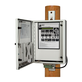
S&C 6800 Series Navigation Manual

S&C 6800 Series Navigation Manual

Automatic switch controls with intelliteam sg automatic restoration system
Hide thumbs Also See for 6800 Series:

Advertisement

Quick Links

6800 Series Automatic Switch Controls with IntelliTeam
Restoration System

Table of Contents

Section
Qualified Persons . . . . . . . . . . . . . . . . . . . . . . . . . . . 2
Read this Instruction Sheet . . . . . . . . . . . . . . . . . . . 2
Retain this Instruction Sheet . . . . . . . . . . . . . . . . . . . 2
Special Warranty Provisions . . . . . . . . . . . . . . . . . . . 2
Understanding Safety-Alert Messages . . . . . . . . . . . 4
Following Safety Instructions . . . . . . . . . . . . . . . . . . 4
Replacement Instructions and Labels . . . . . . . . . . . 4
. . . . . . . . . . . . . . . . . . . . . . . . . 5
. . . . . . . . . . . . . . . . . . . . . . . . . . . . . . . . . . . 6
Log In to the Control . . . . . . . . . . . . . . . . . . . . . . . . . 8
Software Screen Features . . . . . . . . . . . . . . . . . . . . 9
Validate/Apply Screen . . . . . . . . . . . . . . . . . . . . . . . . 9
Security . . . . . . . . . . . . . . . . . . . . . . . . . . . . . . . . . . .10
January 6, 2020
© S&C Electric Company 2020, all rights reserved
Navigation Guide
Page
Section
General Setup . . . . . . . . . . . . . . . . . . . . . . . . . . . . . .11
Sensor Configuration . . . . . . . . . . . . . . . . . . . . . . . .12
Site-Related Settings . . . . . . . . . . . . . . . . . . . . . . . .13
Metering . . . . . . . . . . . . . . . . . . . . . . . . . . . . . . . . . .13
Saving a Memory Snapshot . . . . . . . . . . . . . . . . . . .14
Communications . . . . . . . . . . . . . . . . . . . . . . . . . . . .14
Setpoint Files . . . . . . . . . . . . . . . . . . . . . . . . . . . . . .15
IntelliTeam System Configuration . . . . . . . . . . . . . . .16
Stand-Alone Programming . . . . . . . . . . . . . . . . . . . .16
Automatic Operation . . . . . . . . . . . . . . . . . . . . . . . . .16
SCADA Point Mapping . . . . . . . . . . . . . . . . . . . . . . .17
SG Automatic
®
Instruction Sheet 1045-511
Page

Advertisement

Table of Contents
loading
Need help?

Need help?

Do you have a question about the 6800 Series and is the answer not in the manual?

Questions and answers

Summary of Contents for S&C 6800 Series

  • Page 1: Table Of Contents

    6800 Series Automatic Switch Controls with IntelliTeam SG Automatic ® Restoration System Navigation Guide Table of Contents Section Page Section Page Introduction Qualified Persons . . . . . . . . . . . . . . . . . . . . . . . . . . . 2 General Setup .
  • Page 2: Introduction

    Special Warranty The standard warranty contained in S&C’s standard conditions of sale, as set forth in Price Sheets 150 and 181, applies to the 6800 Series Automatic Switch Control, except Provisions that the first paragraph of the said warranty is replaced by the following:...
  • Page 3 The remedy shall be additional system analysis and reconfiguration of the IntelliTeam SG Automatic Restoration System until the desired result is achieved. Warranty of the 6800 Series Automatic Switch Control is contingent upon the installation, configuration, and use of the control or software in accordance with S&C’s applicable instruction sheets.
  • Page 4: Safety Information

    Understanding Several types of safety-alert messages may appear throughout this instruction sheet and on labels and tags attached to the 6800 Series Automatic Switch Control. Familiarize Safety-Alert yourself with these types of messages and the importance of these various signal words:...
  • Page 5: Safety Precautions

    Safety Precautions DANGER The 6800 Series Automatic Switch Control line voltage input range is 93 to 276 Vac. Failure to observe the precautions below will result in serious personal injury or death. Some of these precautions may differ from your company’s operating procedures and rules .
  • Page 6: Overview

    530, “6800 Series Automatic Switch Controls with IntelliTeam® SG Automatic Restoration System: Setup.” 6800 series controls come in three variants: 6801, 6802 and 6803 controls. The last numeral designates the number of switches that can be controlled by the 6800 control.
  • Page 7 Overview Automatic Restoration mode Automatic Operation mode SCADA Control mode Figure 1. The 6801 control faceplate. SCADA Control mode Automatic Operation mode Automatic Restoration mode Figure 2. The 6801 control Operation screen. S&C Instruction Sheet 1045-511...
  • Page 8: Switch Control Configuration

    Switch Control Confi guration Log In to the Control Follow these steps to log in to an installed switch control: STEP 1. Before arriving at the site, download and install the 6800 Control Software (which includes IntelliLink Setup Software) on a computer. The software can by downloaded at this link: sandc.com/en/support/sc-customer-portal/.
  • Page 9: Software Screen Features

    Switch Control Confi guration Software Screen IntelliLink software screens have a tool bar across the top, a navigation tree on the left and status screens in the center. The communication status is displayed along the bottom. Features There are many tabs and data fi elds on specifi c screens. This guide introduces a small amount of the functionality needed to confi gure the control.
  • Page 10: Security

    Switch Control Configuration Figure 5. The Setup>Validate/Apply screen. Security Security is extremely important for the electric grid. Log-in and password information should never be left set to default entries. To change them, navigate to the Setup>Security screen. See Figure 6. Configure the User Groups, create passwords for each group, and select the access for each group with these checkboxes.
  • Page 11: General Setup

    Switch Control Configuration General Setup In the left menu, select the Setup and General entries to configure settings specific to the control on the Setup>General screen. See Figure 7. The SG6800 tab configures name and location information for the switch control. Name this control in the Device Name field and enter the location in the Device Location field.
  • Page 12: Sensor Configuration

    Switch Control Configuration Sensor Configuration Click on the Sensor Config tab. See Figure 8. This screen configures sensor calibration data for Scada-Mate Switching Systems, and PME, PMH, or Vista Underground Distribution Switchgear sensors. The switch control uses this data to calibrate sensor input to the voltage and current amplitude accuracy specified for S&C Sensors.
  • Page 13: Site-Related Settings

    Switch Control Configuration Site-Related Settings The Site-Related tab configures settings for the specific control site. See Figure 9. Make sure the Line kV to 120 Vac Base Ratio setpoint is correct. This is the voltage step-down ratio of all customer-load transformers on the feeder. The control records, displays, and manipulates voltages normalized on a 120-Volt or 240-Volt base.
  • Page 14: Saving A Memory Snapshot

    Information supplied by the department that supports your field-area net- work is entered on this screen. All the settings are defined in Instruction Sheet 1045-530, “6800 Series Automatic Switch Controls with IntelliTeam® SG Automatic Restoration System: Setup.” Wi-Fi configuration is also covered in this instruction sheet.
  • Page 15: Programming

    Programming NOTICE This section provides a summary of basic programming requirements . Programming should not be started until site and system requirements have been established S&C Instruction Sheet 1045-530, “6800 Series Automatic Switch Controls with IntelliTeam® Automatic Restoration System: Setup” has been thoroughly reviewed . When you have a screen question, press the <F1>...
  • Page 16: Intelliteam System Configuration

    The IntelliTeam® II Automatic Restoration System, the previous version, is configured through the IntelliTeam screens in the IntelliLink software. See S&C Instruction Sheet 1045-530, “6800 Series Automatic Switch Controls with IntelliTeam® SG Automatic Restoration System: Setup” for more information. Stand-Alone In some cases, the 6800 control will be used to sectionalize by detecting phase and ground faults.
  • Page 17: Scada Point Mapping

    Programming SCADA Point Mapping Point mapping assigns point commands and status points in the order required for a specific SCADA system. See Figure 13. In the point list, the left column sets the index position of the selected point defining the order in which the points are returned to SCADA.

This manual is also suitable for:

680168026803

Table of Contents